The universal digital thermostat TR-12V-DS is designed to measure and maintain temperature within specified limits (from -55 to +125°C), and can be widely used for precise temperature control in electrical circuits with a voltage of 12 Volts.
Application area
The temperature regulator TR-12V-DS is most in demand for use in automotive vehicles with a 12V on-board network; can be used in incubators, brooders; in various systems based on batteries, solar panels and other alternative energy sources; in equipment powered by 12 Volts. The temperature sensor is the widely used high-precision digital sensor DS18B20.
Functionality
The climate control thermostat TR-12V-DS measures the temperature value at the location of the sensor and gives a command to turn the load on or off via an electromagnetic relay. Any heating or cooling electrical appliances can be connected to it. At the same time, the maximum power of connected devices should not exceed 2500 Watts of active load (10 Amps at cos ? = 1).
The device has settings for the temperature that must be maintained and hysteresis, that is, the temperature difference between turning on and off the load, thanks to which you can set a wider temperature “corridor” and avoid excessively frequent operation of the relay. The universal thermostat TR-12V-DS can be configured for both heating mode (turning on the heating device when the temperature drops below the set one) and cooling mode (turning on the cooling device when the temperature rises above the set one). In addition, the thermostat has a built-in timer, thanks to which you can program the thermostat to maintain the temperature for a certain time (maintain the temperature for X minutes -> turn off until manually turned on) or to operate in a cyclic mode (maintain the temperature for X minutes -> idle Y minutes -> maintaining temperature...). The device also has the ability to limit the specified upper and lower limits of the maintained temperature range.
The thermostat comes in a small transparent case 6 (8) x 5 x 3 cm and has holes for fastening with self-tapping screws (screws) on any suitable surface.
|
Parameter |
Meaning |
|
Temperature range |
from -55 to +125 °C |
|
Resolution |
0.1 °C, 0.1 °C in the range from -9.9 to +99.9 °C, 1 °C in the range from -55 to -10 °C and from +100 to +125 °C |
|
Temperature measurement error |
|
|
Hysteresis (difference between switch-on and switch-off temperatures) |
plus or minus from 0 to 50.0 °C |
|
Run timer time |
from 0 to 999 minutes |
|
Idle Timer Time |
from 0 to 999 minutes |
|
Sound signaling of the end of the process |
|
|
Selection of operating logic |
heating or cooling |
|
Maximum switching current at cos? =1 |
|
|
Sensor connecting wire length |
|
|
Device supply voltage |
12 Volt AC/DC |
|
Installation (connection) method |
on a flat surface, portable case |
|
dimensions |
6 (8) x 5 x 3 cm |
Hello to all fans of electronic homemade products. Recently I quickly made an electronic thermostat with my own hands; the circuit diagram of the device is very simple. An electromagnetic relay with powerful contacts that can withstand current up to 30 amperes is used as an actuator. Therefore, the homemade product in question can be used for various household needs.
According to the diagram below, the thermostat can be used, for example, for an aquarium or for storing vegetables. Some may find it useful when used in conjunction with an electric boiler, while others may use it for a refrigerator.
DIY electronic thermostat, device diagram

As I already said, the circuit is very simple and contains a minimum of inexpensive and common radio components. Typically, thermostats are built on a comparator microcircuit. Because of this, the device becomes more complicated. This homemade product is built on an adjustable zener diode TL431:

Now let's talk in more detail about the parts that I used.
Device details:
- 12 volt step down transformer
- Diodes; IN4007, or others with similar characteristics 6 pcs.
- Electrolytic capacitors; 1000 microns, 2000 microns, 47 microns
- Stabilizer chip; 7805 or another 5 volt
- Transistor; KT 814A, or other p-n-p with a collector current of at least 0.3 A
- Adjustable zener diode; TL431 or Soviet KR142EN19A
- Resistors; 4.7 Kohm, 160 Kohm, 150 Ohm, 910 Ohm
- Variable resistor; 150 Kom
- Thermistor as a sensor; about 50 Kohm with negative TCS
- Light-emitting diode; any with the lowest current consumption
- Electromagnetic relay; any 12 volt with a current consumption of 100 mA or less
- Button or toggle switch; for manual control
How to make a thermostat with your own hands
A burnt Granit-1 electronic meter was used as a housing. The board on which all the main radio components are located is also from the meter. Inside the case there is a power supply transformer and an electromagnetic relay:


As a relay, I decided to use a car one, which can be purchased at any auto store. Coil operating current is approximately 100 milliamps:


Since the adjustable zener diode is low-power, its maximum current does not exceed 100 milliamps, it will not be possible to directly connect the relay to the zener diode circuit. Therefore, we had to use a more powerful transistor KT814. Of course, the circuit can be simplified if you use a relay whose current through the coil is less than 100 milliamps, for example, or SRA-12VDC-AL. Such relays can be connected directly to the zener diode cathode circuit.
I'll tell you a little about the transformer. The quality I decided to use was non-standard. I have a voltage coil lying around from an old induction meter for electrical energy:

As you can see in the photo there is free space for the secondary winding, I decided to try winding it and see what happens. Of course, the cross-sectional area of the core is small, and therefore the power is small. But for this temperature controller this transformer is sufficient. According to my calculations, I got 45 turns per 1 volt. To obtain 12 volts at the output, you need to wind 540 turns. To fit them I used a wire with a diameter of 0.4 millimeters. Of course, you can use a ready-made one with an output voltage of 12 volts or an adapter.
As you noticed, the circuit contains a 7805 stabilizer with a stabilized output voltage of 5 volts, which powers the control pin of the zener diode. Thanks to this, the temperature controller has stable characteristics that will not change due to changes in the supply voltage.
As a sensor, I used a thermistor, which at room temperature has a resistance of 50 Kom. When heated, the resistance of this resistor decreases:

To protect it from mechanical influences, I used heat-shrinkable tubes:


A place for the variable resistor R1 was found on the right side of the thermostat. Since the resistor axis is very short, I had to solder a flag onto it, which is convenient to turn. On the left side I placed the manual control switch. Using it, it is easy to check the operating status of the device, without changing the set temperature:


Despite the fact that the terminal block of the former electric meter is very bulky, I did not remove it from the housing. It clearly includes a plug from some device, such as an electric heater. By removing the jumper (yellow on the right in the photo) and using an ammeter instead of the jumper, you can measure the current supplied to the load:

Now all that remains is to calibrate the thermostat. For this we need. You need to connect both sensors of the device together using electrical tape:

Use a thermometer to measure the temperature of various hot and cold objects. Using a marker, mark the scale and markings on the thermostat, indicating the moment the relay turns on. I got from 8 to 60 degrees Celsius. If someone needs to shift the operating temperature in one direction or another, this can be easily done by changing the values of resistors R1, R2, R3:

So we made an electronic thermostat with our own hands. Externally it looks like this:

To prevent the inside of the device from being visible through the transparent cover, I closed it with tape, leaving a hole for the HL1 LED. Some radio amateurs who decided to repeat this scheme complain that the relay does not turn on very clearly, as if it was rattling. I didn't notice any of this, the relay turns on and off very clearly. Even with a slight change in temperature, no chattering occurs. If it does occur, you need to select more precisely the capacitor C3 and resistor R5 in the base circuit of the KT814 transistor.
The assembled thermostat according to this scheme turns on the load when the temperature drops. If, on the contrary, someone needs to turn on the load when the temperature rises, then you need to swap sensor R2 with resistors R1, R3.
The universal digital thermostat TR-12V-DS is designed to measure and maintain temperature within specified limits (from -55 to +125°C), and can be widely used for precise temperature control in electrical circuits with a voltage of 12 Volts.
Application area
The temperature regulator TR-12V-DS is most in demand for use in automotive vehicles with a 12V on-board network; can be used in incubators, brooders; in various systems based on batteries, solar panels and other alternative energy sources; in equipment powered by 12 Volts. The temperature sensor is the widely used high-precision digital sensor DS18B20.
Functionality
The climate control thermostat TR-12V-DS measures the temperature value at the location of the sensor and gives a command to turn the load on or off via an electromagnetic relay. Any heating or cooling electrical appliances can be connected to it. At the same time, the maximum power of connected devices should not exceed 2500 Watts of active load (10 Amps at cos ? = 1).
The device has settings for the temperature that must be maintained and hysteresis, that is, the temperature difference between turning on and off the load, thanks to which you can set a wider temperature “corridor” and avoid excessively frequent operation of the relay. The universal thermostat TR-12V-DS can be configured for both heating mode (turning on the heating device when the temperature drops below the set one) and cooling mode (turning on the cooling device when the temperature rises above the set one). In addition, the thermostat has a built-in timer, thanks to which you can program the thermostat to maintain the temperature for a certain time (maintain the temperature for X minutes -> turn off until manually turned on) or to operate in a cyclic mode (maintain the temperature for X minutes -> idle Y minutes -> maintaining temperature...). The device also has the ability to limit the specified upper and lower limits of the maintained temperature range.
The thermostat comes in a small transparent case 6 (8) x 5 x 3 cm and has holes for fastening with self-tapping screws (screws) on any suitable surface.
|
Parameter |
Meaning |
|
Temperature range |
from -55 to +125 °C |
|
Resolution |
0.1 °C, 0.1 °C in the range from -9.9 to +99.9 °C, 1 °C in the range from -55 to -10 °C and from +100 to +125 °C |
|
Temperature measurement error |
|
|
Hysteresis (difference between switch-on and switch-off temperatures) |
plus or minus from 0 to 50.0 °C |
|
Run timer time |
from 0 to 999 minutes |
|
Idle Timer Time |
from 0 to 999 minutes |
|
Sound signaling of the end of the process |
|
|
Selection of operating logic |
heating or cooling |
|
Maximum switching current at cos? =1 |
|
|
Sensor connecting wire length |
|
|
Device supply voltage |
12 Volt AC/DC |
|
Installation (connection) method |
on a flat surface, portable case |
|
dimensions |
6 (8) x 5 x 3 cm |
In this article we will consider devices that support a certain thermal regime, or signal when the desired temperature value has been reached. Such devices have a very wide scope of application: they can maintain a given temperature in incubators and aquariums, heated floors, and even be part of a smart home. For you, we have provided instructions on how to make a thermostat with your own hands and at a minimum cost.
A little theory
The simplest measuring sensors, including those that respond to temperature, consist of a measuring half-arm of two resistances, a reference and an element that changes its resistance depending on the temperature adjusted to it. This is shown more clearly in the picture below.
As can be seen from the diagram, resistor R2 is the measuring element of a homemade thermostat, and R1, R3 and R4 are the reference arm of the device. This is a thermistor. It is a conductor device that changes its resistance with temperature changes.
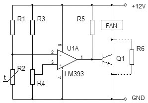
The thermostat element that responds to changes in the state of the measuring arm is an integrated amplifier in comparator mode. This mode abruptly switches the output of the microcircuit from the off state to the operating position. Thus, at the output of the comparator we have only two values “on” and “off”. The load of the chip is a PC fan. When the temperature reaches a certain value in the arm R1 and R2, a voltage shift occurs, the input of the microcircuit compares the value on pins 2 and 3 and the comparator switches. The fan cools the required object, its temperature drops, the resistance of the resistor changes and the comparator turns off the fan. In this way, the temperature is maintained at a given level and the operation of the fan is controlled.
Overview of circuits
The difference voltage from the measuring arm is supplied to a paired transistor with a high gain, and an electromagnetic relay acts as a comparator. When the coil reaches a voltage sufficient to retract the core, it is triggered and connected through its contacts of actuators. When the set temperature is reached, the signal on the transistors decreases, the voltage on the relay coil synchronously drops, and at some point the contacts are disconnected and the payload is turned off.

A feature of this type of relay is the presence of a difference of several degrees between turning on and off a homemade thermostat, due to the presence of an electromechanical relay in the circuit. Thus, the temperature will always fluctuate a few degrees around the desired value. The assembly option provided below is practically free of hysteresis.
Schematic electronic circuit of an analog thermostat for an incubator:

This scheme was very popular for repetition in 2000, but even now it has not lost its relevance and copes with the function assigned to it. If you have access to old parts, you can assemble a thermostat with your own hands almost free of charge.
The heart of the homemade product is the K140UD7 or K140UD8 integrated amplifier. In this case, it is connected with positive feedback and is a comparator. The temperature-sensitive element R5 is a resistor of type MMT-4 with negative TKE, which means that when heated its resistance decreases.
The remote sensor is connected via a shielded wire. To reduce and false trigger the device, the length of the wire should not exceed 1 meter. The load is controlled through thyristor VS1 and the maximum permissible power of the connected heater depends on its rating. In this case, a 150 Watt electronic switch - a thyristor - must be installed on a small radiator to remove heat. The table below shows the ratings of radio elements for assembling a thermostat at home.

The device does not have galvanic isolation from the 220 Volt network; when setting up, be careful; there is mains voltage on the regulator elements, which is life-threatening. After assembly, be sure to insulate all contacts and place the device in a non-conductive housing. The video below shows how to assemble a thermostat using transistors:
Homemade thermostat using transistors
Now we’ll tell you how to make a temperature controller for a heated floor. The working diagram is copied from a serial sample. It will be useful for those who want to familiarize themselves and repeat, or as a sample for troubleshooting the device.
The center of the circuit is a stabilizer chip, connected in an unusual way, LM431 begins to pass current at voltages above 2.5 Volts. This is exactly the size of the internal reference voltage source for this microcircuit. At a lower current value, it does not pass anything. This feature began to be used in all kinds of thermostat circuits.

As you can see, the classic circuit with a measuring arm remains: R5, R4 are additional resistors, and R9 is a thermistor. When the temperature changes, the voltage shifts at input 1 of the microcircuit, and if it reaches the operating threshold, the voltage moves further along the circuit. In this design, the load for the TL431 microcircuit is the operation indication LED HL2 and optocoupler U1, for optical isolation of the power circuit from the control circuits.
As in the previous version, the device does not have a transformer, but receives power from the quenching capacitor circuit C1, R1 and R2, so it is also under life-threatening voltage, and you need to be extremely careful when working with the circuit. To stabilize the voltage and smooth out the ripples of network surges, a zener diode VD2 and a capacitor C3 are installed in the circuit. To visually indicate the presence of voltage, an HL1 LED is installed on the device. The power control element is a VT136 triac with a small harness for control via optocoupler U1.
At these ratings, the control range is within 30-50°C. Despite the apparent complexity at first glance, the design is simple to set up and easy to repeat. A visual diagram of a thermostat on a TL431 chip, with an external 12 volt power supply for use in home automation systems is presented below:
This thermostat is capable of controlling a computer fan, power relays, indicator lights, and sound alarms. To control the temperature of the soldering iron, there is an interesting circuit using the same TL431 integrated circuit.

To measure the temperature of the heating element, a bimetallic thermocouple is used, which can be borrowed from a remote meter in a multimeter or purchased at a specialized radio parts store. To increase the voltage from the thermocouple to the triggering level of TL431, an additional amplifier is installed on LM351. Control is carried out through an optocoupler MOC3021 and triac T1.
When connecting the thermostat to the network, it is necessary to observe the polarity, the minus of the regulator must be on the neutral wire, otherwise phase voltage will appear on the body of the soldering iron, through the thermocouple wires. This is the main drawback of this scheme, because not everyone wants to constantly check that the plug is correctly connected to the socket, and if you neglect this, you can get an electric shock or damage electronic components during soldering. The range is adjusted by resistor R3. This scheme will ensure long-term operation of the soldering iron, eliminate its overheating and increase the quality of soldering due to the stability of the temperature regime.
Another idea for assembling a simple thermostat is discussed in the video:
Temperature controller on TL431 chip
A simple regulator for a soldering iron
The disassembled examples of temperature controllers are quite enough to satisfy the needs of a home craftsman. The schemes do not contain scarce and expensive spare parts, are easily repeated and practically do not require adjustment. These homemade products can easily be adapted to regulate the temperature of water in a water heater tank, monitor the heat in an incubator or greenhouse, and upgrade an iron or soldering iron. In addition, you can restore an old refrigerator by remaking the regulator to work with negative temperature values, by replacing the resistances in the measuring arm. We hope our article was interesting, you found it useful and understood how to make a thermostat with your own hands at home! If you still have questions, feel free to ask them in the comments.
Thermostat for incubator Mechta-12 (12V) with control and regulation of humidity levels, as well as a programmable timer for rotating / changing the position of trays in the incubator, this is a universal electronic device that will provide high-quality and reliable automatic control temperature and humidity in the incubator that you need. Provides control over the rotation of trays at specified time intervals. The device has high measurement and adjustment accuracy. Temperature - 0.1 °C. Humidity – 5%. Supply voltage 12 V.
Purpose and main characteristics
Any egg incubators require constant monitoring of ambient temperature and humidity. The main difficulty in this case is maintaining these parameters at constant values! After all, even 10 minutes of overheating or hypothermia of incubated eggs leads to the death of the embryo.
Humidity also plays an important role during incubation. To measure humidity, a psychrometric method is used, based on the dependence of the difference between the readings of the dry and wet thermometers of the device. This method is one of the most accurate and reliable. You can find out more about this method below.
It is also necessary to turn the eggs after a certain time (at least 3-4 turns per day) throughout the entire incubation period, this is due to the fact that the temperature difference on different sides of the eggs can reach 2 degrees, which leads to a decrease in the hatching of chicks.
To solve these problems, it is necessary to use various temperature and humidity control devices, and various timers. Electronic device DREAM-12 combines all these functions in one device designed and used to regulate temperature and humidity parameters, as well as to control tray turners in incubators.
DREAM-12 is a control device for instrumentation and automation. The device analyzes the information coming from the sensors, analyzes time intervals, and, using a relay, switches the load on external devices that serve to change the climatic conditions in the controlled object, and also, if it is an incubator, turns on the motor of the tray turning device.
To change the temperature, any heating or cooling devices with a current consumption of no more than 16 Amps can be used - electric tubular electric heaters (TEH), incandescent light bulbs, air conditioners, refrigeration units, etc.
To regulate the humidity in the incubator, ultrasonic humidifiers, steam generators, valves of a device that supplies water to wet hanging fabric, heated water containers, compressors that pump air through water containers, etc. can be connected. To reduce humidity, ventilation systems can be connected to the device.
In addition to incubators, the device can also be used to measure and regulate temperature and humidity in various types of premises (storages, greenhouses), in drying chambers, in domestic conditions, as part of a weather station, etc.
Description of the appearance of the device
On the front panel of this model there is:
1. digital indicator displaying current values of temperature, humidity, service information, as well as load status (on or off)
2. control buttons (with the help of which user information is entered into the microcontroller):
M - menu; change in rank.
OK – confirmation; change in number in a place.
For setup and maintenance during operation, it is possible to enter the service menu. Configurable device parameters:
- Operating time of the tray rotation timer;
- Temperature value;
- Humidity value;
- Hysteresis parameters;
- Service parameters from the service menu.
Description psychrometric method“dry-wet thermometer”: a “dry” thermometer shows the temperature of the surrounding air, and a “wet” thermometer, partially placed in distilled water, shows a lower temperature, since water evaporates from its surface due to heat consumption. Evaporation from the surface of a wet thermometer occurs more intensely, the lower the ambient air humidity. The difference in thermometer readings therefore depends on the air humidity. The lower the air humidity, the greater the evaporation rate and the greater the difference in thermometer readings. Knowing the temperature difference, you can use a special psychrometric table and find out the humidity value.
Warranty: 24 months.