Retail prices for 30s41nzh:
| Name of product | Price including VAT, rub. |
| 30s41nzh Du-50 | 3 059,60 |
| 30s41nzh Du-80 | 4 598,20 |
| 30s41nzh Du-100 | 5 994,60 |
| 30s41nzh Du-150 | 12 293,80 |
| 30s41nzh Du-200 | 17 897,60 |
| 30s41nzh Du-250 | 29 584,70 |
| 30s41nzh Du-300 | 38 978,60 |
| 30s41nzh Du-400 | 114 129,60 |
30s41nzh, production of JSC "Foundry-Mechanical Plant", Semenov, Nizhny Novgorod region:
| Name of product | Price including VAT, rub. |
| 30s41nzh (LMZ) Du-80 | 6 216,20 |
| 30s41nzh (LMZ) Du-100 | 8 609,20 |
| 30s41nzh (LMZ) Du-150 | 16 850,40 |
Steel flanged wedge valve with rising spindle 30s41nzh
30s41nzh LMZ
Purpose: designed for installation on a pipeline as a shut-off device.
Working environment: water, steam, oil, oils, petroleum products.
Working environment temperature: up to 425ºС.
Nominal pressure: 1.6 (16) MPa (kgf/cm²).
Pipeline connection: flanged
Material of main parts:
Body, cover, wedge - steel 25L; 35L (20GL; 25HGSL).
Spindle - steel 20Х13 (14Х17Н2).
Flywheel is cast iron.
The gasket under the cover is paronite.
Sealing packing - graflex.
Seal in the valve (surfacing) - 07Х25Н13 (12ХН10Т; 08Х17Т1).
Shutter tightness: class A, B, C, D according to GOST 9544-2005.
Manufacturer:
- , Russian Federation;
- , Russian Federation;
- , Russian Federation;
- Promtrevl LLC, Russian Federation;
- CJSC "ARKOR", RF.
The 30s41nzh valve is installed on the pipeline in places accessible for inspection and maintenance in any position except the flywheel down position. The sealing surfaces of the body and discs for the 30s41nzh valve are made of stainless steel. The clockwise rotational movement of the flywheel through the spindle is converted into the translational movement of the wedge, which, when lowered, fits tightly to the body, creating a tightness on the sealing surfaces and closing the passage hole of the 30s41nzh valve body.
Overall weight and connection dimensions of valves 30s41nzh:
|
Nominal diameter DN, mm |
Length L, mm |
Construction |
Diameter |
Quantity |
Weight, kg |
|
| 345 | 405 | |||||
| 450 | 550 | |||||
| 465 | 570 | |||||
| 280 | 650 | |||||
| 795 | 1015 | |||||
| 950 | 1210 | |||||
| 500 | 1100 | |||||
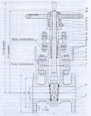
Wedge valve:
1 - body
2 - wedge
3 - gasket
4 — bracket
5; 12; 18 - nut
6; 10 — hairpin
7 - cover
8 — packing of the stuffing box
9 — oil seal
11 — washer
13 - spindle
14 - oiler
15 — bushing
16 — thrust bushing
17 - flywheel
19 — locking screw
The use of 30s41nzh valves as control devices is not allowed. It is necessary to periodically, but at least once a month, completely open and close the valve in order to clean the valve and ensure its long-term performance as a locking device. For timely detection and elimination of faults, it is necessary to periodically inspect and test the valve. As necessary, it is recommended to: lubricate the threaded part of the spindle with NG-203 grease grade B in accordance with GOST 12328-77; tighten the oil seal bushing using folding bolts (when replacing the oil seal without blocking the pipeline, it is necessary to lift the valve to the upper stop and tighten it with the flywheel); lubricate the friction surface of the spindle nut (bearing unit) through a grease nipple with CIATIM-221 GOST 9433-80 lubricant. All valve parts are interchangeable, with the exception of the wedge. It is not recommended to turn the wedge over with the sealing surfaces to avoid loss of tightness.
Manufacturer's guarantees:
Guaranteed shelf life is 3 years from the date of manufacture.
The warranty period is 12 months from the date of commissioning, within the warranty storage period.
The total average service life of the 30s41nzh valve is at least 10 years.
Warranty life: 450 cycles.
Full name Flanged wedge valve 30s41nzh, double-disc with extending spindle Connection type Flange according to GOST 12819-80 Country of manufacture: Russia Manufacturer: "Nitekmash Service" Noginsk Case material: Carbon steel Type of drive: Manual (flywheel) Working environment temperature: up to +425 degrees C Working environment: Water, Steam Tightness class: in accordance with GOST 9544-93, the valve has “A” -
Gate valves 30s41nzh are perhaps the most common type of steel shut-off valves. Many generations of installers, starting from the Soviet past, know perfectly well what we are talking about if a table of figures with the name of a given position is mentioned. The valves described above are an absolutely unified unit of shut-off valves. All their elements were developed by specialists who tried and complied with the established Russian, European, American standards and are therefore allowed to be installed on absolutely any pipelines, the pressure in which is not higher than Ru16 atmospheres.
We also point out that these valves have the most common connection to a pipe - a flange, which also complies with GOST, this makes it possible to repeatedly install the same valve even on different pipelines alternately. Everyone loves domestic fittings due to their low price. See for yourself, compare prices on our website, and you will see that the cost of 30s41nzh is very affordable and will give you the opportunity to save money when drawing up an estimate and subsequent installation.
All technical information, including a drawing, abbreviation decoding, and detailed photos can be viewed by any visitors to this page and our website as a whole. Still have questions regarding the valve description? We ask you not to hesitate to communicate with our technical specialists! Having found out everything that interested you, you can easily buy 30s41nzh and its accessories. Call us, we are waiting for you!
Drawing: overall dimensions and general description of parts
1 - Housing; 2 - Wedge; 3 – Gasket; 4 – Bracket; 5 – Nut; 6 – Hairpin; 7 – Cover; 8 – Stuffing box packing; 9 – Oil seal; 10 - Hairpin; 11 – Washer; 12 – Nut; 13 – Spindle; 14 – Oil can; 15 – Running bushing; 16 – Thrust bushing; 17 – Flywheel; 18 – Nut; 19 – Locking screw
Table 1 – Main geometric parameters of the PN 1.6 MPa valve
DN, mm Dimensions, mm n L D D1 d H1 H2 50 180 160 125 18 345 405 4 80 210 195 160 18 450 550 4 100 230 215 180 18 465 570 8 125 255 245 210 18 501 635 8 150 280 280 240 22 650 820 8 200 330 335 295 22 795 1015 12 250 450 405 355 26 950 1210 12 300 500 460 410 26 1100 1500 12 400 600 580 525 30 1415 1850 16 Design, operation and basic geometric parameters
Each valve consists of the following main parts and assemblies (see Figure 1):
a) housing (item 1)
b) a valve assembly that provides geometric overlap of the valve flow area (item 2)
c) covers (item 7)
d) oil seal assembly (pos. 8, 9)
e) spindle (item 13)
e) control unit - flywheel (pos. 17) with a running sleeve (pos. 15)
Table 2 - Basic technical data and characteristics of valves
Product Table of figures Climatic version according to GOST 15150-69 Material of main body parts Du, mm Maximum torque on the spindle, micron, Nm to close for the opening NM11057-050 or
30ls41nzhU1 25L 50 70,0 90,0 HL1 20GL NM11057-080 U1 25L 80 125,0 145,0 HL1 20GL NM11057-100 U1 25L 100 180,0 200,0 HL1 20GL NM11057-125 U1 25L 125 193,0 208,0 HL1 20GL NM11057-150 U1 25L 150 210,0 220,0 HL1 20GL NM11057-200 U1 25L 200 245,0 260,0 HL1 20GL
Type: steel wedge valve.
The 30s41nzh valve is used as a shut-off device on pipelines transporting water, air, steam, ammonia, natural gas, oil, petroleum products, liquid and gaseous hydrocarbon media at a maximum medium pressure of 1.6 MPa (16 kgf/ cm 2) and maximum operating temperature up to +425 °C.
Gate valves 30s41nzh use a double-disc wedge. The spindle seal is stuffing box. In the upper position of the valve, the spindle has an upper seal along conical surface in the lid.
Basic technical data and parameters of valve 30s41nzh
Working environment: Liquid and gaseous hydrocarbons, oil, petroleum products, natural gas, gas condensate, water steam and other liquids and gases that are non-aggressive to the materials used in the valve.
The corrosion rate of body parts is no more than 0.1 mm/year.
Working environment temperature: from minus 40 o C to plus 425 o C, ambient air not lower than minus 40 o C.
Conditional working pressure: PN 1.6 MPa (16 kgf/cm2).
Connection to the pipeline: connecting dimensions according to GOST 12815-80, version 3, row 2 (default).
Material of main parts: 20L.
Tightness class: A, B, C according to GOST 9544-2005 (upon customer request).
Attention! Valves intended for gaseous, explosive, fire-hazardous and toxic environments are additionally tested with air after hydrotesting. When ordering, you must make a note: “gas”.
Control: manual (flywheel).
Installation position: any.
Climatic design: in accordance with GOST 15150-69 category 1 (for manual valves) and category 2 (for electric valves), version "U1".
Manufacturing and delivery: according to TU 3741-024-57146717-2005.
Overall and connection dimensions of valve 30s41nzh
 |
| 30s41nzh sizes |
|
Weight, kg |
|||||||||
|
1120 |
|||||||||
|
1000 |
1310 |
Materials of the main parts of valve 30s41nzh
1) Housing Steel 20L; 2) Disks Steel 20L or 20X13; 3) Spindle 20Х13 or 14Х17Н2; 4) Gasket Paronit PMB; 5) Cover Steel 20L; 6) Nut Steel 25; 7) Hairpin Steel 35; 8) TRG oil seal packing; 9) Oil seal Steel 20L; 10) Nut Steel 25; 11) Hinged bolt Steel 35; 12) Threaded bushing Lts 40S; 13) Flywheel Steel 20L; 14) Lock nut Steel 35; 15) Key Steel 40X; 16) Axle 20Х13,14Х17Н2. It is allowed to manufacture parts and sealing surfaces from other materials whose properties are not inferior to those indicated above.
Resources and warranties for valves 30s41nzh
Warranty period: 24 months.
Average service life: 10 years.
Average resource: no less than: 2500 cycles.
Mean time between failures: 500 cycles.
Operating principle of valve 30s41nzh
When the flywheel rotates, a threaded bushing rotates, converting the rotational movement into the translational movement of the spindle and wedge, thereby opening or closing the flow area.
Marking.
The side surfaces of the case are marked:
manufacturer's trademark;nominal pressure PN, kgf/cm 2 ;nominal passage DN, mm.
Tips for operating valve 30s41nzh
Installation, operation and repair of valves is permitted to personnel servicing the facility who have studied the design of valves, safety regulations, the requirements of the operating instructions and have the experience of working with valves.
If the 30s41nzh valve is removed from the pipeline, disassembly and assembly of the product must be carried out in a specially equipped room. If the valve is disassembled without removing it from the pipeline, measures must be taken to ensure the cleanliness of the workplace. The possibility of contamination and foreign objects entering the internal cavity of the valve during assembly must be excluded.
When installing fittings in systems, it is necessary to additionally be guided by the general technical conditions for the manufacture, acceptance and installation of systems and the instructions of the technical conditions developed for each system.
The working media passing through the valves must comply with the standards and technical specifications on them. The valves must be opened fully.
Safety requirements for installation and operation in accordance with GOST 12.2.063-81. Maintenance personnel carrying out work on preservation and re-preservation of valves must have individual protective equipment (goggles, gloves, overalls...) and comply with fire safety rules.
To ensure operational safety, IT IS STRICTLY PROHIBITED:
remove valves from the pipeline if there is a working medium in it;use wrenches larger than required and extensions to the wrenches for fasteners;disassemble valves when there is pressure from the working medium in the pipeline;use gate valves for parameters;operate valves with damaged warranty seals;valves, regardless of the medium, operating pressure and temperature, should be used on pipelines subject to vibration;replace the stuffing box, refill or tighten the stuffing box if there is pressure in the system.
Installation procedure for valve 30s41nzh
Transportation of 30s41nzh valves subjected to preservation to the installation site must be carried out in the manufacturer's packaging. It is allowed to remove plugs and re-preserve valves only before installing them on the pipeline.
Before installing valves on the pipeline, check: condition of packaging, installation of valves and availability of operational documentation;the presence of plugs on the main pipes; the condition of the internal cavities of the valves accessible to visual inspection;tightness of the valve, gasket connections, and seal.
Preservation lubricants should be removed with a clean rag moistened with a solvent (gasoline, white spirit, etc.).
When installing for suspension and other work, use the housing pipes.
During installation, it is prohibited to use a flywheel for suspension.
Before installing valves, the pipeline must be cleaned of dirt, sand, scale, etc. When installing fittings on a pipeline, it is necessary that the flanges on the pipeline are installed without distortions. It is prohibited to eliminate distortions of the pipeline flanges by tensioning (deforming) the valve flanges. Do not place individual parts, installation tools or foreign objects on the valves. The bolts must be tightened with nuts evenly, without distortion.
Before starting the system, immediately after installation, all valves must be opened and the pipeline systems must be flushed.
During the commissioning period, multiple pressure testing of valves as part of the system in which they are installed is allowed. The frequency, duration and number of pressure tests are according to the system testing conditions, with a pressure of no more than 1.25 PN.
During crimping locking device the product must be in one of the extreme positions. Opening and closing the product during crimp testing is not allowed. Operating procedure.
During operation, periodic inspections (routine work) should be carried out within the time limits established by the schedule, depending on the operating mode of the system (unit). During the inspection it is necessary to check: general condition of the valves;condition of fastening connections;tightness of joints;performance of the valve.
Possible malfunctions of the 30s41nzh valve and methods for eliminating them
|
Name of the malfunction, external manifestation, additional symptoms |
Probable Cause |
|
1. Violation of the seal of the shutter. Passage of medium when the shutter is closed. |
1. Hit foreign body between the sealing surfaces of the wedge and the body. 2. Damage to sealing surfaces. |
|
2. The tightness of the body-lid connection is broken. Passing the medium through the connection. |
1. The gasket is not sealed sufficiently, the fasteners are loosened. 2. The gasket is damaged. |
|
3. The tightness of the oil seal is broken. Passing the medium through the stuffing box. |
1. Insufficient tightening force of the oil seal. 2. Development of the oil seal (fluoroplastic rings). |
|
4. The valve does not close or open. |
1. Jamming of moving parts. |
The procedure for disassembling and assembling valves 30s41nzh
When disassembling and assembling valves, be sure to:
protect sealing, guide and threaded surfaces from damage;prevent dirt and foreign objects from entering the internal cavities of 30s41nzh valves and pipelines;Disassembly and assembly should be carried out using standard tools.
Disassembly and reassembly of valves is carried out to eliminate malfunctions that arise during operation.It is allowed to disassemble and reassemble products, both within the pipeline and outside the pipeline, taking into account ease of maintenance and observing safety requirements.
Complete disassembly of the valves is carried out in the following order:
a) remove the wedge gate from the “closed” position; b) remove flywheel 9, unscrew the flywheel nut 10;c) unscrew the nuts 14, remove the cover 8, with the spindle and wedge, protecting the sealing surfaces from damage;d) remove the wedge from the spindle;e) remove gasket 11 from body 1;f) unscrew the nuts 13, remove the studs 17, unscrew the spindle 3 from the threaded bushing 5, holding the bushing 5, remove it from the cover 8, remove the threaded bushing 5;g) remove flange 12, bushing 7, remove ring 4.
Before assembly, clean all parts from contamination and apply lubricant to parts and friction points in accordance with the requirements of the technical documentation.Reassemble the valves in the reverse order.
Products assembled after eliminating defects must be subjected to the following tests:
1) The tightness test of the gasket joint and stuffing box seal should be carried out with water at a pressure PN specified in the design documentation. It is allowed to test with air at a pressure of at least 0.6 MPa (6 kgf/cm2).Tests are carried out by supplying air into one of the pipes with the other pipe plugged and the valve half-open.The duration of exposure at steady pressure is at least 3 minutes, after which inspect the product.The passage of medium in places of gasket connections and oil seals is not allowed. The control method is visual.
The tightness of the stuffing box seal should be additionally checked by raising and lowering the valve three times throughout the entire working stroke.
2) Tests for tightness in the valve should be carried out by alternately supplying water and air at pressure PN into one of the nozzles with the valve closed. The second pipe is plugged with a flange with a drain pipe for measuring leaks. It is allowed to carry out tests with air pressure of at least 0.6 MPa (6 kgf/cm2).The amount of leakage should not exceed the standards for class A tightness GOST 9544-93.Control is carried out using a graduated cylinder.
3) When testing for performance, it is necessary to carry out one “open-closed” cycle without water pressure on the valve and three “open-closed” cycles with one-sided water pressure on the closed valve, followed by opening and releasing pressure in outlet pipeline.
Rules for transportation and storage of valves 30s41nzh
Transportation conditions - 7 (Zh1) GOST 15150-69. Packaging - according to GOST 5762-74. Conservation - according to GOST 9.014-78.
When installing 30s41nzh valves for long-term storage, the following requirements must be observed:
Valves must be stored in conditions that guarantee them from damage and contamination;
The valve must be closed, the passage holes must be closed with plugs;
at long-term storage valves must be inspected periodically as needed, but at least once a year.
If the preservation is violated or its validity period expires, the valves should be re-preserved.
Operation and storage of valve 30s41nzh
Conditions of storage and transportation 4 (Zh2), for export and to countries with tropical climates 6 (OZh2) according to GOST 15150. The procedure for preparing and checking the readiness of the product for use. Before installing the fittings on the pipeline, flush and purge the pipeline system. Check the condition of the fasteners, the absence of media passage through the metal, the tightness of the gasket connections and the seal, the tightness of the valve, and the operability of the fittings. Before installing the fittings, visually check the condition of the internal cavities and, if necessary, rinse and dry.
List of special safety measures during installation and operation.
Installation, operation and maintenance of valves is permitted only to personnel who have studied the design of valves, the requirements of the operating manual and have the skills to work with valves.
The fittings must be clearly marked and distinctively painted in accordance with GOST 4666. The forces on the flywheel and torques must not exceed the maximum permissible values.
Tighten the studs with nuts evenly, without distortions or overtightening. Gate valves 30s41nzh can be used as part of systems that are subjected to multiple pressure tests of no more than 1.25 PN during commissioning.
Loading and unloading operations must be carried out in accordance with GOST 12.3.009. Slinging must be done in accordance with the operating instructions. The 30s41nzh valve should not experience loads from the pipeline. If necessary, supports or compensators must be provided.
Operate the valves without operating documentation in accordance with GOST 2.601. Carry out dismantling and repair work when there is pressure in the valve cavity. Replace the oil seal packing, refill, tighten the oil seal if there is pressure in the system. Remove the fittings from the pipeline if there is a medium in it. Use fittings as a pipeline support or as a control valve.
- Water supply
- Electric power industry
- Chemical production
- Oil and gas pipelines
- Heat supply
Manufactured according to technical specifications, GOST, ST TsKBA, GOST R standards and design documentation. They have certificates of compliance with the requirements of the Technical Regulations of the Russian Federation on the safety of machinery and equipment.
Each valve undergoes quality control and testing.
| Nominal diameter, DN | 150…1200 mm |
|---|---|
| Nominal pressure, PN | 1.6…2.5 MPa |
| Tightness class according to GOST 9544-2005 | A, B, C, D |
| Pipeline connection | flanged according to GOST 12815-80, GOST R 54432-2011 or welded |
| Construction length | according to GOST 3706-93 |
| Total average service life not less than | 15 years |
| Warranty time | 500 cycles |
| Warranty period of operation of version Art. 20 | 12 months from the date of commissioning, but not more than 18 months from the date of shipment from the manufacturer |
| Warranty period for the operation of the HL, NZH, NZHM versions | 18 months from the date of commissioning, but not more than 24 months from the date of shipment from the manufacturer |
- Gate valves produced by the Admiral valve plant are made in a rectangular welded body with a standard face-to-face length in accordance with GOST 3706-93 and have less weight compared to cast ones.
- The body parts are ribbed to increase rigidity under the influence of working environment pressure.
- The double-disc self-aligning wedge promotes stable performance of high tightness and increased maintainability.
- The weight reduction of the wedge is ensured by the use of hydroforming of the discs.
- The valves are manufactured with full bore, which allows passage of cleaning and diagnostic devices.
- Tightness is ensured by welding of corrosion- and wear-resistant wire on the sealing surfaces of the disk and housing. In relation to the external environment, tightness is ensured by the stuffing box seal and the body-cover gasket.
- O-rings of the stuffing box assembly made of various materials(selected according to customer requirements) reduce frictional wear of the spindle and increase the durability of the stuffing box assembly.
- The bronze running nut is located outside the working chamber, which increases its service life.
- The limiting nut at the end of the spindle protects against excessive load on the locking element if the electric drive is incorrectly configured.
- In the stainless steel version, the side and connecting (body-cover) flanges are made of carbon steel with corrosion-resistant surfacing of the sealing surfaces to protect against exposure to the working environment.
Not only its reliability, but also its durability largely depends on the correct selection of the gearbox. Errors in calculation and selection can inevitably lead to premature failure and, as a result, in the best case, to financial losses.
Experienced specialists will take into account all factors: from the location of the mechanism in space and operating conditions to its heating temperature during operation.
Practice shows that a properly selected gearbox provides a service life of at least 5 years for worm and slider models and 10-12 years for cylindrical ones.
| DN, mm | PN, MPa | Machov/reducer | Connection type | Max. torque, Nm | Number of rotations of the sleeve open/close. | Electric drive | Opening/closing time, min | |||
|---|---|---|---|---|---|---|---|---|---|---|
| TsKBA | ISO | Tulaelectro drive unit |
AUMA | Tulaelectro drive unit |
AUMA | |||||
| 150 | 1,6 | +/+ | AC | F10 | 90 | 34 | N-A-11 | SA 10.2 | 1,4 | 1,5 |
| 200 | 1,6 | +/+ | B | F14 | 160 | 39 | N-B-03 | SA 14.2 | 1,6 | 1,8 |
| 250 | 1,6 | +/+ | B | F14 | 210 | 47 | N-B-03 | SA 14.2 | 1,9 | 1,9 |
| 300 | 1,6 | +/+ | IN | F14 | 300 | 55 | N-B-03 | SA 14.2 | 2,2 | 2,5 |
| 350 | 1,6 | +/+ | IN | F14 | 350 | 45 | N-B-03 | SA 14.2 | 1,8 | 2,0 |
| 400 | 1,6 | +/+ | IN | F16 | 680 | 56 | N-B-03 | SA 16.2 | 2,3 | 2,5 |
| 500 | 1,6 | -/+ | IN | F25 | 770 | 62 | N-B-16 | GST 25.2+SA 14.2 | 2,6 | 3,0 |
| 600 | 1,6 | -/+ | G | F30 | 1350 | 79 | N-G-03 | GST 30.2+SA 14.2 | 3,8 | 3,4 |
| 700 | 1,6 | -/+ | G | F30 | 2400 | 77 | N-G-03 | GST 30.2+SA 14.2 | 3,9 | 3,5 |
| 800 | 1,6 | -/+ | G | F30 | 2490 | 80 | N-G-03 | GST 30.2+SA 14.2 | 4,0 | 3,6 |
| 1000 | 1.6 | -/+ | D | F40 | 6480 | 83 | N-D-03 | GST 40.2+SA 16.2 | 8,3 | 7,5 |
| 1200 | 1,6 | -/+ | D | F40 | 10000 | 100 | N-D-09 | GST 40.2+SA 16.2 | 10,0 | 9,1 |
* calculation of opening and closing time with AUMA drive is given for 11, 22, 45 rpm cam bushing.
| № | the name of detail | Material | |||
|---|---|---|---|---|---|
| Spanish St20 | Spanish 09G2S | Spanish nj* | Spanish NJM* | ||
| 1 | Frame | St20 | 09G2S |
08Х18Н10Т (AISI 321) 08Х18Н10 (AISI 304) |
10Х17Н13М2 (AISI 316) |
| 2 | Lid | St20 | 09G2S |
08Х18Н10Т (AISI 321) 08Х18Н10 (AISI 304) |
10Х17Н13М2 (AISI 316) |
| 3 | Disk | St20 | 09G2S |
08Х18Н10Т (AISI 321) 08Х18Н10 (AISI 304) |
10Х17Н13М2 (AISI 316) |
| 4 | Seal in housing |
stainless surfacing TsN-6L |
|||
| 5 | Seal on disc | stainless surfacing TsN-6L | CN - 12M | ||
| 6 | Spindle |
20Х13 thermoformed |
14Х17Н2 thermoprocessed |
08Х18Н10Т (AISI 321) 08Х18Н10 (AISI 304) |
10Х17Н13М2 (AISI 316) |
| 7 | Spindle seal** | TRG stuffing box | |||
| 8 | Running nut | BrAZHNMts10-3-1.5 | |||
| Fasteners | |||||
| Gaskets *** |
from TRG sheet |
||||
| Climatic version according to GOST 15150-69 |
U (-40...+40 0 C), T (-10...+50 0 C) |
HL (-60…+40 0 C) |
U (-40…+40 0 C), T (-10…+50 0 C) |
||
| Working environment temperature | -40 0 С…+350 0 С |
60 0 С…+250 0 С |
40 0 С…+400 0 С |
||
* in the stainless steel version, the fins and flanges are made of St20, with stainless surfacing of the flange sealing surfaces. At customer's request, it is possible to manufacture fins and flanges from stainless steel.
** at a working environment temperature from -60 0 C to 250 0 C, the AP-31 stuffing box is used.
*** at working environment temperatures from -40 0 C to 150 0 C, paronite gaskets are used.
| DN, mm | PN, MPa | Table figure*** | Designation according to design documentation | N, mm | Н1, mm | h, mm | L, mm | B, mm | D1, mm* | d, mm* | n, pcs.* | Weight, kg** flanged (welded) |
| 150 | 1,6 | 30s41nzh | AB13070-150 | 875 | 735 | 140 | 350 | 410 | 240 | 22 | 8 | 136 (120) |
| 200 | 1,6 | 30s41nzh | AB13070-200 | 1028 | 860 | 168 | 400 | 465 | 295 | 22 | 12 | 179 (158) |
| 250 | 1,6 | 30s41nzh | AB13070-250 | 1188 | 985 | 203 | 450 | 535 | 355 | 26 | 12 | 249 (220) |
| 300 | 1,6 | 30s41nzh | AB13070-300 | 1385 | 1155 | 230 | 500 | 590 | 410 | 26 | 12 | 341 (305) |
| 350 | 1,6 | 30s41nzh | AB13070-350 | 1540 | 1280 | 260 | 550 | 650 | 470 | 26 | 16 | 406 (360) |
| 400 | 1,6 | 30s41nzh | AB13070-400 | 1695 | 1405 | 290 | 600 | 710 | 525 | 30 | 16 | 481 (419) |
| 500 | 1,6 | 30s541nzh 30s941nzh |
AB13070-500 | 2010 | 1655 | 355 | 700 | 840 | 650 | 33 | 20 | 767 (653) |
| 600 | 1,6 | 30s541nzh 30s941nzh |
AB13070-600 | 2325 | 1905 | 420 | 800 | 970 | 770 | 39 | 20 | 1121 (963) |
| 700 | 1,6 | 30s541nzh 30s941nzh |
AB13070-700 | 2640 | 2185 | 455 | 900 | 1040 | 840 | 39 | 24 | 1443 (1275) |
| 800 | 1,6 | 30s541nzh 30s941nzh |
AB13070-800 | 2869 | 2359 | 510 | 1000 | 1118 | 950 | 39 | 24 | 1894 (1798) |
| 1000 | 1,6 | 30s541nzh 30s941nzh |
AB13070-1000 | 3598 | 2970 | 628 | 1200 | 1385 | 1170 | 45 | 28 | 3807 (3649) |
| 1200 | 1,6 | AB13070-1200 | 4295 | 3552 | 743 | 1400 | 1615 | 1390 | 52 | 32 | 4931 (4335) |
* flange dimensions are given according to GOST 12815-80.
** the weight given in the table is theoretical and may differ to some extent from the actual one.
*** At the customer's request, it is possible to manufacture a stainless steel version of the valve (tabular figure not shown).
Completeness
The delivery set includes: valve, passport, operational documentation. At the customer's request, the valves can be additionally equipped with counter flanges, gaskets, fasteners, and electric actuators.
Notes
The appearance and design of the valve can be changed in the process of improvement without special notice, without deteriorating consumer properties and subject to delivery of the product with the ordered parameters.
It is possible to manufacture other versions according to DN and PN, which are not listed in this catalog, and for drives according to EN ISO 5210, EN ISO 5211, DIN 3210, DIN 3338.
Brief description of the design features of the valve 30s41nzh
On pipelines through which liquid and gaseous media pass, they are used to block their flows. Valves can only operate to open or close a pipeline; they cannot be used to regulate medium flows. Without exaggeration, we can say that the most commonly used valve is a 30s41nzh wedge valve with a sliding spindle. The demand for this type of shut-off valve is explained by its design, which is clear from the name itself - 30s41nzh wedge gate valve. The valve body contains so-called seats that form a small angle. When closing, the locking element is tightly located between the seats; the force on the spindle additionally expands the wedge, which ensures high tightness of the shutter.
Gate valve 30s41nzh. Specifications:
Let's decipher it. “Wedge” means that the sealing surfaces of the valve are placed at an angle relative to each other, and the locking element is wedge-shaped. There are three types of locking element:
Double-disk, consists of two disks connected to each other and having the ability to self-install relative to the seats. The advantage of the steel 30c41nzh double-disc valve is that it rarely jams. The steel wedge valve with a rising spindle, flanged 30s41nzh, is structurally more complex than other types of wedge valves, but provides high level tightness and durability. During operation, the seal does not wear out significantly. Closing or opening the flanged valve 30s41nzh does not require much effort.
Rigid (monolithic) will provide the valve with the highest class of valve tightness, but at the same time the valve very often jams. The longer the 30s41nzh is used, the more difficult it is to open and close it, as the seal wears out. Difficulties with controlling the steel valve 30s41nzh ru16 also arise when there are significant temperature fluctuations.
The elastic, in this case, locking element of the valve consists either of a pair of disks that are connected by an elastic material, or of two rigidly connected disks. A wedge valve with a sliding spindle 30s41nzh with an elastic wedge provides a high class of tightness, the wedge does not stick at high temperatures, and operating the valve does not require much effort.
30s41nzh decoding: “30” means that shut-off valves refers to the type of valves. “C” - the body is made of steel 20. “41” - model number. “NZH” - the sealing surfaces in the product are made of stainless steel.
The equipment puts additional load on the pipeline. The probability of accidents occurring on a pipeline is closely related to the load on it. When assembling a pipeline, it is necessary to carefully monitor the weight of the equipment. For example, a steel gate valve 30s41nzh, the weight of which can be found in the “Main Dimensions and Parameters” section, compares favorably in weight with the cast version.
Wedge gate valve with a retractable spindle 30s41nzh and a non-retractable spindle.
To shut off the flow of the medium, a steel wedge valve with a retractable spindle, flanged 30s41nzh, and a steel valve 30s41nzh Ru 16 with a non-retractable spindle can be used. According to the type of connection of equipment to the pipeline, a flanged valve 30s41nzh, and for welding, are used.
Among the product range of the Admiral Valve Plant there is a steel gate valve 30s41nzh ru16 with a sliding spindle. Features of the design produced by the Admiral plant:
Finned body parts,
Double-disc wedge with increased maintainability,
The 30s41nzh valve has a reduced wedge weight,
Selecting o-rings increases the service life of the stuffing box assembly and reduces spindle wear.
The valve 30s41nzh du300 ru16 is in great demand; the price can be calculated on the website by filling out the form. At the Admiral plant you can purchase flanged steel wedge valves with a rising spindle up to DN 1200.
, , .