Flange is a way of connecting pipes, valves, pumps and other equipment to form a piping system. This connection method provides easy access for cleaning, inspection or modification. Flanges are usually threaded or welded. The flange connection consists of two flanges fixed with bolts and a gasket between them to ensure tightness.
Pipe flanges are made from various materials. Flanges are surface machined, cast iron and nodular iron, but the most commonly used material is forged carbon steel.
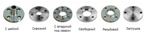
The most used flanges in the oil and chemical industry:
- with welding neck
- through flange
- welded with a recess for welding
- welded overlap (free-rotating)
- threaded flange
- flange plug
All types of flanges, except free, have a reinforced surface.
Special flanges
With the exception of the flanges mentioned above, there are a number of special flanges, such as:
- diaphragm flange
- long welded collar flanges
- expansion flange
- adapter flange
- ring plug (part of the flange connection)
- disc plugs and intermediate rings (part of the flange connection)
The most common materials used for flanges are carbon steel, stainless steel, cast iron, aluminium, brass, bronze, plastic, etc. In addition, flanges, like fittings and pipes for special applications, are sometimes internally coated with a layer of material of a completely different quality than the flanges themselves. These are lined flanges. The material of the flanges is most often set when selecting pipes. As a rule, the flange is made of the same material as the pipes themselves.
Example of a 6" collar weld flange - 150#-S40
Each ASME B16.5 flange has a number of standard sizes. If a designer in Japan, or a project builder in Canada, or a pipeline installer in Australia, speaks of a 6"-150#-S40 welding flange conforming to ASME B16.5, they are referring to the flange shown below. 
In the case of ordering a flange, the supplier would like to know the quality of the material. For example, ASTM A105 is a stamped carbon steel flange while A182 is a stamped alloy steel flange. Thus, by regulation, both standards must be specified for the supplier: Weld Flange 6"-150#-S40-ASME B16.5/ASTM A105.
PRESSURE CLASS
The pressure class or rating for flanges will be in pounds. Different names are used to indicate the pressure class. For example: 150 Lb or 150Lbs or 150# or Class 150, mean the same thing.
Forged steel flanges have 7 main classifications:
150 lbs - 300 lbs - 400 lbs - 600 lbs - 900 lbs - 1500 lbs - 2500 lbs
The concept of flange classification is clear and obvious. A Class 300 flange can handle higher pressures than a Class 150 flange because a Class 300 flange has more metal and can withstand higher pressures. However, there are a number of factors that can affect the flange pressure limit.
EXAMPLE
Flanges can withstand different pressures at different temperatures. As the temperature rises, the pressure class of the flange decreases. For example, a Class 150 flange is rated at approximately 270 PSIG at ambient, 180 PSIG at 200°C, 150 PSIG at 315°C, and 75 PSIG at 426°C.
Additional factors are that flanges can be made from various materials such as alloy steel, cast and ductile iron, etc. Each material has different pressure classes.
PARAMETER "PRESSURE-TEMPERATURE"
The pressure-temperature class defines the operating, maximum allowable overpressure in bar at a temperature in degrees Celsius. For intermediate temperatures, linear interpolation is allowed. Interpolation between notation classes is not allowed.
Temperature-pressure classifications
The Temperature-Pressure class is applicable to flange connections that comply with the limits on bolted connections and gaskets that are made in accordance with good practice for assembly and alignment. Use of these classes for flange connections that do not meet these limits is the responsibility of the user.
The temperature shown for the corresponding pressure class is the temperature of the inner shell of the part. Basically, this temperature is the same as that of the contained liquid. In accordance with the requirements of current codes and regulations, when using a pressure class corresponding to a temperature different from the flowing liquid, all responsibility lies with the customer. For any temperature below -29°C, the rating must be no higher than when used at -29°C.
As an example, below you will find two tables with material groups in accordance with ASTM and two other tables with the temperature-pressure class for these materials in accordance with ASME B16.5.
| Materials ASTM group 2-1.1 |
|||
| Nominal designation |
Stamping |
Casting |
plates |
| C-Si | A105(1) | A216 Gr.WCB(1) |
A515 Gr.70(1) |
| C-Mn-Si | A350 Gr.LF2(1) | - | A516 Gr.70(1),(2) |
| C-Mn-Si-V | A350 Gr.LF6 Cl 1(3) | - | A537 Cl.1(4) |
| 3½ Ni |
A350 Gr.LF3 |
- | - |
REMARKS:
|
|||
| Temperature-Pressure Class for ASTM Group 2-1.1 Materials Operating pressure by class |
|||||||
| Temperature °C | 150 | 300 |
400 |
600 |
900 |
1500 |
2500 |
| from 29 to 38 |
19.6 | 51.1 | 68.1 | 102.1 | 153.2 | 255.3 | 425.5 |
| 50 | 19.2 | 50.1 | 66.8 | 100.2 | 150.4 | 250.6 | 417.7 |
| 100 | 17.7 | 46.6 | 62.1 | 93.2 | 139.8 | 233 | 388.3 |
| 150 | 15.8 | 45.1 | 60.1 | 90.2 | 135.2 | 225.4 | 375.6 |
| 200 | 13.8 | 43.8 | 58.4 | 87.6 | 131.4 | 219 | 365 |
| 250 | 12.1 | 41.9 | 55.9 | 83.9 | 125.8 | 209.7 | 349.5 |
| 300 | 10.2 | 39.8 | 53.1 | 79.6 | 119.5 | 199.1 | 331.8 |
| 325 | 9.3 | 38.7 | 51.6 | 77.4 | 116.1 | 193.6 | 322.6 |
| 350 | 8.4 | 37.6 | 50.1 | 75.1 | 112.7 | 187.8 | 313 |
| 375 | 7.4 | 36.4 | 48.5 | 72.7 | 109.1 | 181.8 | 303.1 |
| 400 | 6.5 | 34.7 | 46.3 | 69.4 | 104.2 | 173.6 | 289.3 |
| 425 | 5.5 | 28.8 | 38.4 | 57.5 | 86.3 | 143.8 | 239.7 |
| 450 | 4.6 | 23 | 30.7 | 46 | 69 | 115 | 191.7 |
| 475 | 3.7 | 17.4 | 23.2 | 34.9 | 52.3 | 87.2 | 145.3 |
| 500 | 2.8 | 11.8 | 15.7 | 23.5 | 35.3 | 58.8 | 97.9 |
| 538 | 1.4 | 5.9 | 7.9 | 11.8 | 17.7 | 29.5 | 49.2 |
| Temperature-Pressure Class for ASTM Group 2-2.3 Materials Operating pressure by class |
|||||||
| Temperature °C | 150 | 300 |
400 |
600 |
900 |
1500 |
2500 |
| from 29 to 38 |
15.9 |
41.4 |
55.2 |
82.7 |
124.1 |
206.8 |
344.7 |
| 50 | 15.3 |
40 |
53.4 |
80 |
120.1 |
200.1 |
333.5 |
| 100 | 13.3 |
34.8 |
46.4 |
69.6 |
104.4 |
173.9 |
289.9 |
| 150 | 12 |
31.4 |
41.9 |
62.8 |
94.2 |
157 |
261.6 |
| 200 | 11.2 |
29.2 |
38.9 |
58.3 |
87.5 |
145.8 |
243 |
| 250 | 10.5 |
27.5 |
36.6 |
54.9 |
82.4 |
137.3 |
228.9 |
| 300 | 10 |
26.1 |
34.8 |
52.1 |
78.2 |
130.3 |
217.2 |
| 325 | 9.3 |
25.5 |
34 |
51 |
76.4 |
127.4 |
212.3 |
| 350 | 8.4 |
25.1 |
33.4 |
50.1 |
75.2 |
125.4 |
208.9 |
| 375 | 7.4 |
24.8 |
33 |
49.5 |
74.3 |
123.8 |
206.3 |
| 400 | 6.5 |
24.3 |
32.4 |
48.6 |
72.9 |
121.5 |
202.5 |
| 425 | 5.5 |
23.9 |
31.8 |
47.7 |
71.6 |
119.3 |
198.8 |
| 450 | 4.6 |
23.4 |
31.2 |
46.8 |
70.2 | 117.1 |
195.1 |
FLANGE SURFACE
The shape and design of the flange surface will determine where the sealing ring or gasket will be located.
Most used types:
- raised surface (RF)
- flat surface (FF)
- o-ring groove (RTJ)
- with male and female thread (M&F)
- tongue and groove (T&G)
Raised face, the most applicable type of flange, easy to identify. This type is so called because the surface of the gasket protrudes above the surface of the bolted joint. 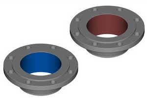
Diameter and height are defined in accordance with ASME B16.5 using pressure class and diameter. In the pressure class up to 300 Lbs, the height is about 1.6 mm, and in the pressure class from 400 to 2500 Lbs, the height is about 6.4 mm. The pressure class of the flange determines the height of the raised face. The purpose of an (RF) flange is to concentrate more pressure on a smaller gasket area, thereby increasing the pressure limit of the joint.
For the height parameters of all flanges described in this article, dimensions H and B are used, with the exception of the lap joint flange, this must be understood and remembered as follows:
In pressure classes 150 and 300 Lbs, the protrusion height is approximately 1.6 mm (1/16 inch). Almost all suppliers of flanges in these two classes list dimensions H and B in their brochures or catalogues, including the face (see Fig.1 below) 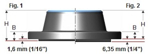
In pressure classes 400, 600, 900, 1500 and 2500 Lbs, the protrusion height is 1/4 in. (6.4 mm). In these classes, many suppliers list the H and B dimensions, not including the protrusion height (see Fig.2 above)
In this article you will find two sizes. The top row of dimensions does not include protrusion height, and the dimensions in the bottom row include protrusion height.
FLAT SURFACE (FF - Flat Face)
For a flat face (full face) flange, the gasket is in the same plane as the bolted connection. Most often, flat face flanges are used where the mating flange or fitting is cast. 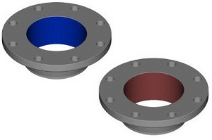
A flat face flange never connects to a raised flange. According to ASME B31.1, when connecting cast iron flat flanges to carbon steel flanges, the protrusion on the steel flange must be removed and the entire surface must be sealed with a gasket. This is done to keep the thin, brittle cast iron flange from cracking due to the protrusion of the steel flange.
FLANGE WITH ROOT FOR O-RING SEAL (RTJ - Ring Type Joint)
RTJ flanges have grooves cut into their surface, into which steel o-rings are inserted. The flanges are sealed due to the fact that when the bolts are tightened, the gasket between the flanges is pressed into the grooves, deformed, creating close metal-to-metal contact. 
The RTJ flange may have a lip with an annular groove made in it. This protrusion does not serve as a seal of any kind. For RTJ flanges that are sealed with O-rings, the raised faces of the mated and tightened flanges may come into contact with each other. In this case, the compressed gasket will no longer carry additional loads, bolt tightening, vibration and displacement will no longer crush the gasket and reduce the tightening force.
Metal o-rings are suitable for use at high temperatures and pressures. They are made with the right choice of material and profile and are always used in the appropriate flanges, providing a good and reliable seal.
O-rings are designed so that sealing is achieved by a "leading line of contact" or wedging between the mating flange and the gasket. By applying pressure to the seal through the bolting, the softer metal of the gasket penetrates the fine structure of the stiffer flange material, and creates a very tight and effective seal. 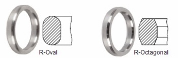
Most used rings:
Type R-Oval according to ASME B16.20
Suitable for ASME B16.5 flanges pressure class 150 to 2500.
Type R-Octagonal according to ASME 16.20
An improved design over the original R-Oval. However, they can only be used for flat flanges with a groove. Suitable for ASME B16.5 flanges pressure class 15 to 2500.
FLANGES WITH SEALING AND SURFACE TYPE LUG-VESSEL (LMF - Large Male Face; LFF - Large Female Face)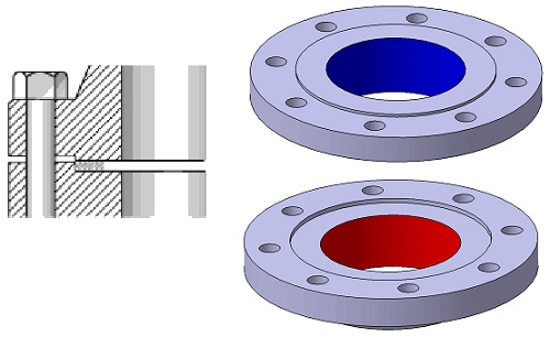
Flanges of this type must match. One flange face has an area that extends beyond the normal flange face limits ( dad). The other flange or counter flange has a corresponding recess ( Mother) made in its surface.
Semi-loose laying
- The depth of the undercut (notch) is usually equal to or less than the height of the protrusion to prevent metal-to-metal contact when the gasket is compressed
- Depth of notch is typically no more than 1/16" greater than the height of the lip
FLANGE WITH SEALING SURFACE
(Protrusion - Tounge Face - TF; Depression - Groove Face - GF)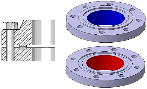
Flanges of this type must also match. One flange has a ring with a protrusion (thorn) made on the surface of this flange, while a groove is machined on the surface of the counterpart. Such surfaces are commonly found on pump covers and valve covers.
Fixed gasket
- Gasket dimensions are the same or less than the height of the groove
- Gasket wider than groove no more than 1/16"
- The dimensions of the gasket will match the dimensions of the groove
- When disassembling, the connection must be unclenched separately
FLAT SURFACE AND GROOVE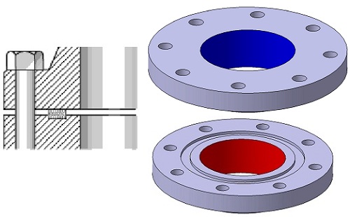
Fixed gasket
- One surface is flat, the other is notched
- For applications where precise control of gasket compression is required
- Only resilient gaskets are recommended - spiral, hollow ring, pressure actuated and metal sheath gaskets
FLANGE SURFACE FINISHING
ASME B16.5 requires the flange surface (raised face and flat face) to have a certain roughness so that this surface, when aligned with the gasket, provides a good seal. 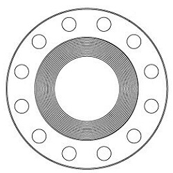
The final fluting, either concentric or spiral, requires 30 to 55 grooves per inch, resulting in a roughness between 125 and 500 micro inches. This will allow flange manufacturers to process any class of metal flange gasket.
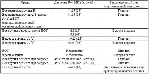
For pipelines transporting substances of groups A and B of technological facilities of explosion category I, it is not allowed to use flange connections with a smooth sealing surface, except for the cases of using spiral wound gaskets.
MOST USED SURFACES
Roughing
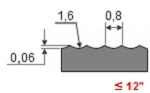
| The most commonly used in the machining of any flange because it is suitable for almost all common operating conditions. When compressed, the soft surface of the gasket will engage the machined surface to help create a seal, and there is a high level of friction between the connected parts. Finishing for these flanges is done with a 1.6mm radius cutter at a feed rate of 0.88mm per revolution for 12". For 14" and larger, machining is done with a 3.2mm radius cutter at a 1.2mm feed vice versa. |
 |
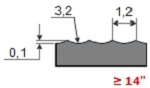 |
Spiral notch
 This can be a continuous or phonographic spiral groove, but differs from roughing in that the groove is obtained by using a 90 degree cutter that creates a V-profile with a 45° fluted angle.
 Concentric notch.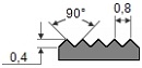 As the name suggests, the machining consists of concentric grooves. A 90° cutter is used and the rings are distributed evenly over the entire surface.
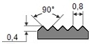
Smooth surface.![]() Such processing does not visually leave traces of the tool. Such surfaces are typically used for metal faced gaskets such as double sheathed, flat steel, or corrugated metal. A smooth surface helps create a seal and depends on the flatness of the opposite surface. This is typically achieved by a gasket contact surface formed by a continuous (sometimes called phonographic) helical groove made with a 0.8 mm radius cutter, at a feed rate of 0.3 mm per revolution, 0.05 mm deep. This will result in a roughness between Ra 3.2 and 6.3 micrometers (125-250 micro inches)
Such processing does not visually leave traces of the tool. Such surfaces are typically used for metal faced gaskets such as double sheathed, flat steel, or corrugated metal. A smooth surface helps create a seal and depends on the flatness of the opposite surface. This is typically achieved by a gasket contact surface formed by a continuous (sometimes called phonographic) helical groove made with a 0.8 mm radius cutter, at a feed rate of 0.3 mm per revolution, 0.05 mm deep. This will result in a roughness between Ra 3.2 and 6.3 micrometers (125-250 micro inches)
GASKETS
In order to make a tight flange connection, gaskets are needed. 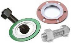
Gasket is compressed sheets or rings used to create a waterproof connection between two surfaces. Gaskets are manufactured to withstand extreme temperatures and pressures and are available in metallic, semi-metallic and non-metallic materials.
For example, the sealing principle may be to compress a gasket between two flanges. The gasket fills the microscopic spaces and surface irregularities of the flanges and then forms a seal that prevents leakage of liquids and gases. Proper and careful gasket installation is required to prevent leakage in the flange connection.
This article will describe gaskets conforming to ASME B16.20 (Metallic and Semi-Metallic Pipe Flange Gaskets) and ASME B16.21 (Non-Metallic, Flat Pipe Flange Gaskets)
BOLTS
Bolts are required to connect two flanges to each other. The number will be determined by the number of holes in the flange, and the diameter and length of the bolts will depend on the type of flange and its pressure class. The most commonly used bolts in the oil and chemical industry for ASME B16.5 flanges are studs. The stud consists of a threaded rod and two nuts. Another type of bolt available is the regular hex bolt with one nut.
Dimensions, dimensional tolerances, etc. have been defined in ASME B16.5 and ASME B18.2.2, materials in various ASTM standards.
TORQUE
To obtain a tight flange connection, the gasket must be properly installed, the bolts must have the correct tightening torque, and the total tightening stress must be evenly distributed over the entire flange. 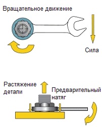
The necessary stretching is carried out due to the tightening torque (applying a preload to the fastener by turning its nut).
The correct tightening torque of the bolt allows the best use of its elastic properties. To do its job well, a bolt must behave like a spring. During operation, the tightening process places an axial, pre-load on the bolt. Of course, this tensile force is equal to the opposing compressive forces applied to the assembly components. It may be referred to as tightening force or tensile force.
TORQUE WRENCH
A torque wrench is a generic name for a hand tool that is used to apply precise torque to a joint, be it a bolt or a nut. This allows the operator to measure the rotational force (torque) applied to the bolt, which must match the specification. 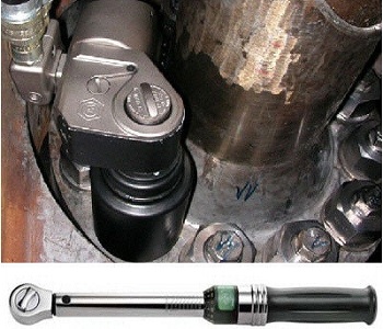
Choosing the right flange bolt tightening technique requires experience. The correct application of any of the techniques also requires the qualifications of both the tool to be used and the specialist who will do the work. Below are the most commonly used bolt tightening methods:
- tightening by hand
- pneumatic wrench
- hydraulic torque wrench
- manual torque wrench with rocker or gear
- hydraulic bolt tensioner
Torque loss is inherent in any bolted connection. The combined effect of bolt loosening, (about 10% during the first 24 hours after installation), gasket creep, vibration in the system, thermal expansion, and elastic interaction during bolt tightening contribute to torque loss. When the torque loss reaches a critical point, the internal pressure exceeds the compression force that holds the gasket in place, in which case leakage or blowout may occur.
The key to reducing these effects is proper gasket placement. When installing the gasket, it is necessary to bring the flanges together and smoothly and parallel, with the least tightening torque, tighten the 4 bolts, following the correct tightening sequence. This will reduce operating costs and improve safety.
The correct thickness of the gasket is also important. The thicker the gasket, the higher its creep, which in turn can lead to loss of tightening torque. The ASME standard for serrated flanges generally recommends a 1.6 mm gasket. Thinner materials can operate at higher gasket loads and therefore higher internal pressures.
LUBRICATION REDUCE FRICTION
Lubrication reduces friction during tightening, reduces bolt shedding during installation, and increases service life. A change in the coefficient of friction affects the amount of preload achieved at a given tightening torque. A larger coefficient of friction results in less conversion of torque into preload. The value of the coefficient of friction provided by the lubricant manufacturer must be known in order to accurately set the required torque value.
Grease or anti-seize compounds must be applied to both the surface of the bearing nut and the male thread.
TIGHTENING SEQUENCE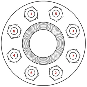 First pass, lightly tighten the first bolt, then the next one opposite it, then a quarter turn in a circle (or 90 degrees) to tighten the third bolt and, opposite it, the fourth. Continue this sequence until all bolts are tightened. When tightening four-bolt flanges, use a criss-cross pattern.
PREPARATION OF FIXING THE FLANGE
In order to achieve tightness in flange connections, it is necessary that all components are accurate.
Before starting the connection process, the following steps must be taken to avoid problems in the future:
- Clean the flange surfaces and check for scratches, the surfaces must be clean and free from any defects (bumps, pits, dents, etc.)
- Inspect all bolts and nuts for damage or thread corrosion. Replace or repair bolts or nuts as needed
- Remove burrs from all threads
- Lubricate the threads of the bolts or studs and the surfaces of the nuts adjacent to the flange or washer. In most applications, hardened washers are recommended.
- Install the new gasket and make sure it is centered. DO NOT USE AN OLD GASKET, or use multiple gaskets.
- Check flange alignment per ASME B31.3 process piping standard
- Adjust the position of the nuts to make sure that 2-3 threads are above the top of the thread.