Threaded connections are the most common type of detachable connections. They are carried out using fasteners threaded parts (bolts, screws, studs, nuts, etc.)
Advantages: reliability, ease of assembly / disassembly, simplicity of design, low cost (due to standardization), manufacturability, the ability to adjust the compression force.
Flaws: stress concentration in thread cavities, low vibration cost.
On the development of a cylindrical surface, the helix is located at a certain angle ψ , this angle is called the lead angle.
The thread stroke, which is the distance between the same points of the same helix. The main characteristic of the thread profile is the angle between adjacent sides in the plane of the axial section, called thread profile angle. For triangular profile metric thread, inch , trapezoid .
There are two main ways to make threads: tapping and rolling. Threading is carried out with cutters, combs, dies, taps, threaded heads, cutters.
Thread rolling is carried out by combs or rollers on thread rolling machines by plastic deformation of the workpiece. This method is highly productive, used in mass production in the manufacture of standard fasteners.
The main geometric parameters of a cylindrical thread are:
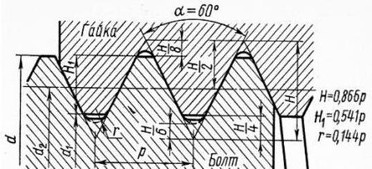
d- outer diameter (nominal thread diameter);
d1- inner diameter of the nut thread;
d2- average thread diameter, i.e. the diameter of an imaginary cylinder on which the thickness of the coil is equal to the width of the cavity;
p- thread pitch, i.e. the distance between the sides of the same name of two adjacent turns in the axial direction;
ph- thread stroke, i.e. the distance between like sides of the same coil in the axial direction;
α
- thread profile angle;
42. The moment of friction in the thread and at the end of the nut (screw). Calculation of thread for shear and shear stress. Nut height and screwing depth.
Overwhelming majority threaded connections with preload. The tightening is created during assembly so that after the application of the working load, there is no opening of the joint or shift of the parts to be joined.
When screwing a nut (or a cap screw), it is necessary to apply a tightening torque T head to overcome the moment T R of resistance in the thread and the moment T T of resistance at the end of the nut:
T head \u003d T R + T T, (2.1)
where T P \u003d F t d 2 / 2 \u003d 0.5 F zat d 2 tg (Ψ + φ 1) ; (2.2)
T T \u003d 0.5 F zat f T d cf, (2.3)
F zat - axial tightening force;
d2 is the average thread diameter;
Ψ – thread helix angle;
φ 1 - reduced (taking into account the influence of the profile angle α) friction angle in the thread: φ 1 = φ / cos (α / 2),
φ is the friction angle of the materials of the screw-nut pair;
f T is the coefficient of friction of the materials of the nut-part pair;
d cf - the average diameter of the ring (Fig. 2.2):
 dav = 0.5(D + dh).
The operation of threaded connections shows that the failure of bolts, screws, studs, etc. parts occurs due to rupture (or stretching) of their rod along the thread or transitional section at the head. The destruction or damage of thread elements occurs less frequently and is typical for parts that are often subjected to disassembly and assembly. If necessary, check the thread strength calculations for shear and shear stresses.
The thread shear strength condition has the form
τ cp = Q/A cp) ≤[τ cp ],
Where Q– axial force; Aср is the cut area of the threaded turns; for screw (see fig.1.9) A cp = π d 1 kH g, for nut A cp = π DkH g.Here H g - nut height; k– coefficient taking into account the width of the thread base: for metric screw threads k≈ 0.75, for nut k≈ 0.88; for trapezoidal and thrust threads (see fig. 1.11, 1.12) k≈ 0.65; for rectangular thread (see fig. 1.13) k= 0.5. If the screw and nut are of the same material, then only the screw is checked for shear, since d l < D.
Thread strength condition to the crush has the form
σ cm = Q/A cm ≤[σ cm ],
Where A cm - conditional crushing area (projection of the contact area of the screw and nut threads on a plane perpendicular to the axis): A cm = π d 2 hz, where (see Fig.1.9) nd 2 – the length of one turn along the average diameter; h- working height of the thread profile; z= H G / R - number of threads in a nut height H G; R- thread pitch (according to the standard, the working height of the thread profile is indicated H 1).
From the condition of equal strength of the bolt rod in tension under the action of the axial load and the thread of the nut in bending, shearing and crushing, the required height of the nut is determined. It has been established that the first thread from the point of application of force takes 34% of the total load, the second - 23%, the third - 15%, and the tenth - only 0.9%. Thus, all turns of the nut thread after the tenth one practically do not perceive any load.
Just like the thread of a nut, the thread of the socket works, into which a screw or stud is screwed. Depending on the material from which the parts into which the studs are screwed are made, the depth of screwing in the studs also changes. Here, the magnitude of the axial load is already taken into account, because the larger it is, the larger the diameter of the stud, and the greater the screwing depth.
To determine the thread pitch p, we find from the thread wear resistance condition (1) the working height of the profile H 1 .
We preliminarily set the number of turns of the nut z from the range 6 ... 12, let z = 10.
Then from the wear resistance condition (1) the working height of the thread profile:
where d 2 \u003d 18 mm is the average diameter from the calculation (3),
The minimum value of the thread pitch, given that , we find by the formula
3.3 Thread parameters from GOST 9484-81 (GOST 10177-82).
For values d 2 = 18 mm (from (3)) and p min = 3.6 mm (from (5)) from GOST 9484-81, a thread with
d \u003d 20 mm, d 2 \u003d 18 mm, p \u003d 4 mm, d 3 \u003d 15.5 mm.
4 Checking the spindle for stability
We will check the screw for stability according to the method from the manual.
A screw having flexibility >50 may lose stability under the action of a compressive force F.
Checking the propeller for stability is reduced to the fulfillment of the condition
F ≤ F cr /S ,
where F cr \u003d cr A - the critical force at which the screw loses stability,
cr - critical stress,
A \u003d 188 mm 2 - area of \u200b\u200bthe dangerous section (see clause 6);
S4 - minimum allowable margin of safety.
The critical stress is calculated depending on the slenderness value:
if 90, then according to the Euler formula kr =,
where E 2 10 5 MPa is the modulus of elasticity for steel;
if 50 ≤ < 90 kr 490 - 2.6 ,
with flexibility less than 50, the loss of stability by the propeller is impossible.
Screw Flexibility
where =2 - length reduction factor for jacks;
l r l- the estimated height of the screw,
l= 150 mm - the height of the load;
3.875mm - radius of gyration of the propeller along the inner diameter ( d 3 or d 1).
77,42 < 90.
Critical stress cr =288.7 MPa , critical force F cr =288.7*18854275.6 MPa, stability condition
F= 10000 HF cr /4 = 54275.6/413568.9H
Performed.
5 Checking the self-braking condition.
The self-braking condition is observed if the helix angle of the thread (thread helix angle) is less than the reduced friction angle " (Figure 4, b).


Figure 4 - .
At the same time, the margin for self-braking sk
K \u003d "/ 1.2. (6)
Thread helix angle (see Figure 4, a) at n=1 (calculation is carried out for the average thread diameter)
![]() ,
,
reduced friction angle
" ![]() ,
,
where f = 0.1 - coefficient of friction of the screw-nut pair.
Self-braking margin
K \u003d "/ \u003d 6 / 4.05 1.48\u003e 1.2.
Therefore, the screw pair has self-braking.
6 Choosing the shape of the heel and calculating the moment of friction in the heel
We select the annular support surface commonly used in jacks (Figure 6). The inner diameter of the ring D 0 for jacks can be found from the ratio:
Ring outer diameter D we determine, based on the allowable specific pressure on the supporting surface of the cup,
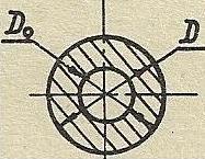
Figure 6 - .
for steel surfaces [q] =12 MPa, therefore:
![]() .
.
The moment of friction in the annular heel (between the end of the screw and the bearing surface of the cup)
15225.53 N mm,
Where f 1 \u003d 0.12 - coefficient of sliding friction for a combination of steel-steel materials.
7 Checking the lead screw for strength
In the screw shaft under load F compressive and torsion stresses arise (see Fig. 1). Calculation formula for equivalent voltage.
As experience shows, unsatisfactory operation of screw gears is most often caused by thread wear.
Therefore, the basic calculation of all screw gears is wear calculation, as a result of which the diameter of the screw and the height of the nut are determined. Checking the mean pressure R in a thread, it is assumed that all threads are loaded evenly.
Figure 20 - Calculation of the screw-nut transmission for wear resistance
The calculation of the transmission for wear resistance is carried out from the condition of not squeezing out the lubricant, assuming that due to running-in, the load is distributed evenly over the threads:
p out \u003d F a / Az in \u003d F a / (d 2 × H 1 × z in) ≤ [p] out, (15)
Where F a– external axial force;
A- the area of the working surface of the coil;
d 2 - average thread diameter;
H 1 - working height of the thread profile;
z b is the number of turns in a nut with a height H: z e = Н/р (here R- thread pitch); [p] out - allowable pressure (selected according to Table 2).
Table 2 - Permissible pressure in the thread for a pair of "screw-nut"
Note. For infrequent work, as well as for nuts of low height, the value [p] out can be increased by 20%.
For the design calculation, it is advisable to transform the resulting formula by replacing z with (H / p p), denoting ψ H \u003d H / d 2 - nut height factor, ψ h = h/p p - thread height factor.
Then (Fig. 20):
 , (16)
Take ψ h \u003d 0.5 for trapezoidal and ψ h \u003d 0.75 for thrust threads; ψ h = 1.2 - 2.5 depending on design considerations ( big values for threads of smaller diameters). Received value d 2 consistent with the standard.
After calculating the thread, heavily loaded screws, such as jack screws, are checked for strength, taking [] = 0.3 t, and for stability.
Transmission efficiency sliding screw-nut
In a sliding screw-nut transmission, losses occur in the thread and in the bearings. Thread losses are the main part. They depend on the thread profile, its lead, the material of the screw pair, manufacturing accuracy, the roughness of the contact surfaces and the type of lubricant:
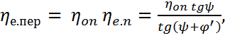 (24)
(24)
where η on is a coefficient that takes into account losses in supports. This coefficient depends on the design of the screw mechanism. So, for the lead screws of machine tools (supports - rolling bearings) η on = 0.98.
The order of the task number 2
Calculation procedure:
Select the initial data in accordance with the number of the option given in Table 3.
 ,
,
where ψ H is the nut height factor;
ψ h - thread height factor;
[p] out - allowable pressure in the thread.
3. From table 4, based on the calculated average diameter d 2, write out the parameters of the thrust thread:
d - outside diameter external thread(screw);
d 1 - inner diameter of the external thread;
d 2 - the average diameter of the external thread;
d 3 - inner diameter of the external thread;
P - thread pitch;
h is the height of the external thread profile.
4. Determine the lead angle of the thread and the reduced angle of friction.
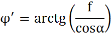 ,
,
where φ' is the reduced friction angle; f is the coefficient of friction (f = 0.1); α - thread angle (α = 15°).
 ,
,
where ψ is the angle of the thread; z = 1 (single start thread); P - thread pitch; d 2 - the average diameter of the external thread.
5. Determine the dimensions of the nut.
a) Nut height: ![]() .
.
b) Number of turns in the nut:
The number of turns of the nut is allowed up to 12.
c) Nut outside diameter: ![]()
d) Nut flange diameter: ![]()
e) Nut flange height: ![]()
6. Check the number of turns and the height of the nut.
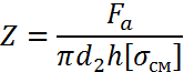 ,
,
where z is the number of turns; d 2 - average thread diameter; h is the height of the external thread profile; [ cm] \u003d [p] out - allowable pressure in the thread.
![]() .
.
where H is the height of the nut; z is the number of turns; P - thread pitch.
7. Determine the efficiency of the jack.

8. State the results in the form of calculations.


