a) measured or multiple measured length with an allowance for each cut of 5 mm and a longitudinal deviation over the entire length plus 10 mm;
b) of unmeasured length.
By agreement between the manufacturer and the consumer, in a batch of unmeasured water and gas pipes up to 5% of pipes with a length of 1.5 to 4 m are allowed.
For threads made by rolling on a pipe, it is allowed to reduce its internal diameter by up to 10% along the entire length of the thread. Weight 1 m water and gas pipe calculated at a steel density of 7.85 g/cm. Galvanized water and gas pipes heavier than non-galvanized ones by 3%.
Note: The maximum deviation in the positive direction in wall thickness is limited by the maximum deviations in mass water and gas pipes. Water and gas pipes of standard manufacturing precision are used for water supply, gas pipelines and heating systems.
Water and gas pipes with increased manufacturing precision are used for parts of water and gas pipeline structures.
Maximum deviations in the mass of pipes should not exceed +8%. At the request of the consumer, maximum deviations in weight should not exceed: +7.5% - for a batch; + 10% - for a separate pipe.
The curvature of water and gas pipes per 1 m of length should not exceed: 2 mm - with a nominal diameter of up to 20 mm inclusive; 1.5 mm - with a nominal bore over 20 mm.
Water and gas pipes with a nominal diameter of 6, 8, 10, 15 and 20 mm are wound into coils at the request of the consumer. Examples of symbols:
An ordinary pipe, non-galvanized, of normal manufacturing precision, of unmeasured length, with a nominal bore of 20 mm, a wall thickness of 2.8 mm, without threads and without a coupling: pipe 20x2.8 GOST 3262-75.
The same, with a coupling: pipe M-20x2.8 GOST 3262-75.
The same, measured length, with thread: pipe R-20x2, 8-4000 GOST 3262-75.
For water and gas pipes for rolling threads in symbol After the word “pipe” the letter N is indicated.
For water and gas pipes with long threads, the letter D is indicated in the symbol after the word “pipe”.
For water and gas pipes with increased manufacturing precision, the letter P is indicated in the symbol after the size of the nominal diameter.
Parameters of water and gas pipes (GOST 3262-75)
| DU Conditional designation | Outer diameter, mm | Lungs | Regular | Reinforced | ||||||
| Wall thickness, mm | Weight 1m, kg | Meters per ton | Wall thickness, mm | Weight 1m, kg | Meters per ton | Wall thickness, mm | Weight 1m, kg | Meters per ton | ||
| 6 | 10,2 | 1,8 | 0,37 | 2681,8 | 2,0 | 0,40 | 2472,5 | 2,5 | 0,47 | 2106,4 |
| 8 | 13,5 | 2,0 | 0,57 | 1763,0 | 2,2 | 0,61 | 1631,1 | 2,8 | 0,74 | 1353,4 |
| 10 | 17,0 | 2,0 | 0,74 | 1351,6 | 2,8 | 0,98 | 1019,8 | 2,8 | 0,98 | 1019,8 |
| 15 | 21,3 | 2,5 | 1,16 | 862,7 | 2,8 | 1,28 | 782,8 | 3,2 | 1,43 | 700,1 |
| 20 | 26,8 | 2,5 | 1,50 | 667,5 | 2,8 | 1,66 | 603,4 | 3,2 | 1,86 | 536,9 |
| 25 | 33,5 | 2,8 | 2,12 | 471,7 | 3,2 | 2,39 | 418,2 | 4,0 | 2,91 | 343,6 |
| 32 | 42,3 | 2,8 | 2,73 | 366,6 | 3,2 | 3,09 | 324,1 | 4,0 | 3,78 | 264,7 |
| 40 | 48,0 | 3,0 | 3,33 | 300,4 | 3,5 | 3,84 | 260,3 | 4,0 | 4,34 | 230,4 |
| 50 | 60,0 | 3,0 | 4,22 | 237,1 | 3,5 | 4,88 | 205,1 | 4,5 | 6,16 | 162,4 |
| 65 | 75,5 | 3,2 | 5,71 | 175,3 | 4,0 | 7,05 | 141,8 | 4,5 | 7,88 | 126,9 |
| 80 | 88,5 | 3,5 | 7,34 | 136,3 | 4,0 | 8,34 | 120,0 | 4,5 | 9,32 | 107,3 |
| 90 | 101,3 | 3,5 | 8,44 | 118,5 | 4,0 | 9,60 | 104,2 | 4,5 | 10,74 | 93,1 |
| 100 | 114,0 | 4,0 | 10,85 | 92,2 | 4,5 | 12,15 | 82,3 | 5,0 | 13,44 | 74,4 |
| 125 | 140,0 | 4,0 | 13,42 | 74,5 | 4,5 | 15,04 | 66,5 | 5,5 | 18,24 | 54,8 |
| 150 | 165,0 | 4,0 | 15,88 | 63,0 | 4,5 | 17,81 | 56,1 | 5,5 | 21,63 | 46,2 |
Galvanized and non-galvanized (black) steel water and gas pipes with cut or rolled cylindrical threads and without threads are manufactured according to the nominal diameter (DN) and wall thickness according to GOST 3262-75 .
The range of pipes must correspond GOST 3262-75 .
According to the length of the pipe they are made:
- measured length - from 4 before 12m;
- of unmeasured length, within measured length.
- ordinary accuracy;
- increased accuracy.
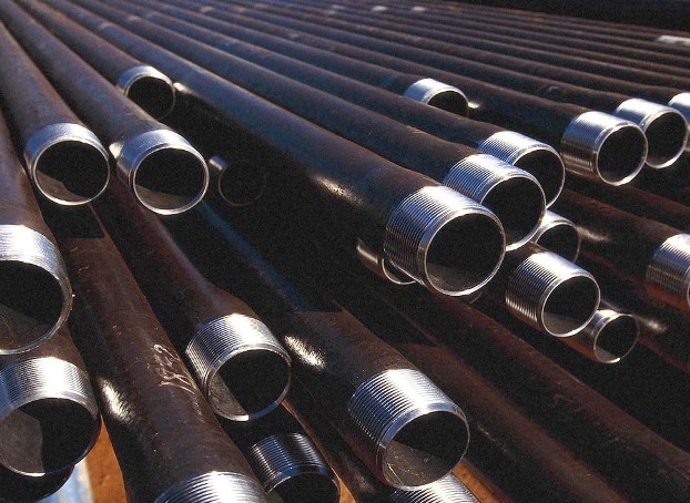
Pipes of the VGP category are a group of water and gas pipes made of steel. Moreover, there are galvanized and non-galvanized options. The pipes are hollow, cylindrical in shape, with a longitudinal weld.
The category has three wall thickness options - thick-walled, medium and thin-walled. A range of this nature makes it possible to use pipes that are specifically suited to the specific project in which they are used.
Product parameters
The name speaks for itself - a pipe of this type can be used both in water supply systems and in gas pipelines. In principle, VGP pipe is considered a universal option for many applications.
Standard pipes have segment lengths from 4 m to 12 m. Moreover, there is a choice of material - without thread, or with cylindrical or knurled threads at the ends. Moreover, it can be short or long - it all depends on the nuances of use.
Typically, a VGP pipe has three strength categories:
- Ordinary.
- Lungs.
- Reinforced.
Although such pipes are heavier than non-galvanized ones, by about 3%, the coating gives excellent results when liquids pass through the pipeline. The pipe does not rust, and its service life is extended significantly.
Advantages of VGP pipes
- Standard pipes VGP GOST 3262 75 are made of high quality steel.
- The so-called “black pipes” of the VGP have a reinforced weld.
- Pipes of this type have three categories convenient for the consumer - light, reinforced and ordinary. This allows you to choose the right option for the ideal design of the highway.
- The threads on the ends of the pipes can be long, short, or applied, depending on the customer’s wishes, on the desired side in the required parameters.
- Pipes of this category are supplied either with or without couplings.
- Pipe parameters can be indicated in inches, which is considered the norm.
- The pipes sold undergo mandatory hydro-vortex control, so compliance with the standards can be considered almost perfect.
- Low cost with excellent product quality is a guarantee of the assigned standards and regulations.
- Versatility in use. Pipes of the required type are ideal for installation and repair work of almost any category.
- A huge range of types of pipes - from hot-rolled seamless, to cold-rolled and electric-welded options.
- Availability of component elements - flanges, couplings, tees, bends, transitions, etc., as well as the possibility of their easy use in installation work.
As you understand, standard VGP pipes GOST 3262 75 have a wide range of applications. The presence of at least three types of this type makes it possible to use them in almost all areas of pipelines. Moreover, it is possible to select a category for the type of main line, with a rich selection of pipe types for its installation.
/ GOST 3262-75. Steel water and gas pipes. Specifications.
Updated: 02/09/2006
UDC 669.14-462:006.354 Group B62
STEEL WATER AND GAS PIPES
TECHNICAL CONDITIONS
GOST 3262-75
PUBLISHING HOUSE OF STANDARDS
STATE STANDARD OF THE USSR UNION
STEEL WATER AND GAS PIPES GOST
Specifications 3262-75
water-supply and gas-supply steel pipes
technical conditions
OKP 138500, OKP 138501
Date of introduction 01.01.77
This standard applies to non-galvanized and galvanized steel welded pipes with cut or rolled cylindrical threads and without threads, used for water and gas pipelines, heating systems, as well as for parts of water and gas pipeline structures.
1. ASSORTMENT
1.1. Pipes are manufactured according to the dimensions and weight given in table. 1.
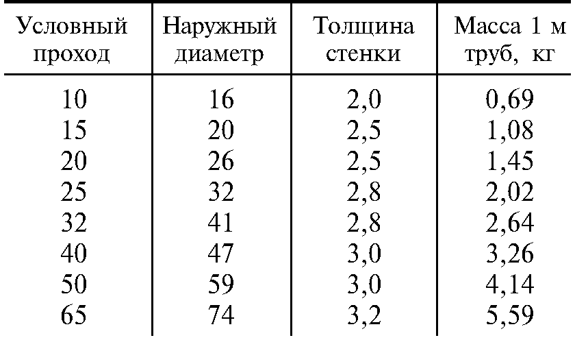
At the consumer's request, light series pipes intended for thread rolling are manufactured according to the dimensions and weight given in table. 2.
1.2. The length of the pipe is made from 4 to 12 m:
a) measured or multiple measured length with an allowance for each cut of 5 mm and a maximum deviation for the entire length plus 10 mm;
b) of unmeasured length.
By agreement between the manufacturer and the consumer, up to 5% of pipes with a length of 1.5 to 4 m are allowed in a batch of unmeasured pipes.
Table 1
| Conditional pass | Outside diameter | Pipe wall thickness | Weight of 1 m of pipes, kg |
||||
| lungs | ordinary | reinforced | lungs | ordinary | reinforced |
||
| 10,2 | 0,37 | 0,40 | 0,47 |
||||
| 13,5 | 0,57 | 0,61 | 0,74 |
||||
| 17,0 | 0,74 | 0,80 | 0,98 |
||||
| 21,3 | 2,35 | 1,10 | |||||
| 21,3 | 1,16 | 1,28 | 1,43 |
||||
| 26,8 | 2,35 | 1,42 | |||||
| 26,8 | 1,66 | 1,86 |
|||||
| 33,5 | 2,12 | 2,39 | 2,91 |
||||
| 42,3 | 2,73 | 3,09 | 3,78 |
||||
| 48,0 | 3,33 | 3,84 | 4,34 |
||||
| 60,0 | 4,22 | 4,88 | 6,16 |
||||
| 75,5 | 5,71 | 7,05 | 7,88 |
||||
| 88,5 | 7,34 | 8,34 | 9,32 |
||||
| 101,3 | 8,44 | 9,60 | 10,74 |
||||
| 114,0 | 10,85 | 12,15 | 13,44 |
||||
| 140,0 | 13,42 | 15,04 | 18,24 |
||||
| 165,0 | 15,88 | 17,81 | 21,63 |
||||
table 2
| Conditional pass | Outside diameter | Wall thickness | Weight of 1 m of pipes, kg |
| 0,69 |
|||
| 1,08 |
|||
| 1,45 |
|||
| 2,02 |
|||
| 2,64 |
|||
| 3,26 |
|||
| 4,14 |
|||
| 5,59 |
Notes:
1. For threads made by rolling on a pipe, its internal diameter is allowed to be reduced by up to 10% along the entire length of the thread.
2. The mass of 1 m of pipes is calculated at a steel density of 7.85 g/cm 3 . Galvanized pipes are 3% heavier than non-galvanized ones.
(Changed edition, Amendment No. 1, 3)
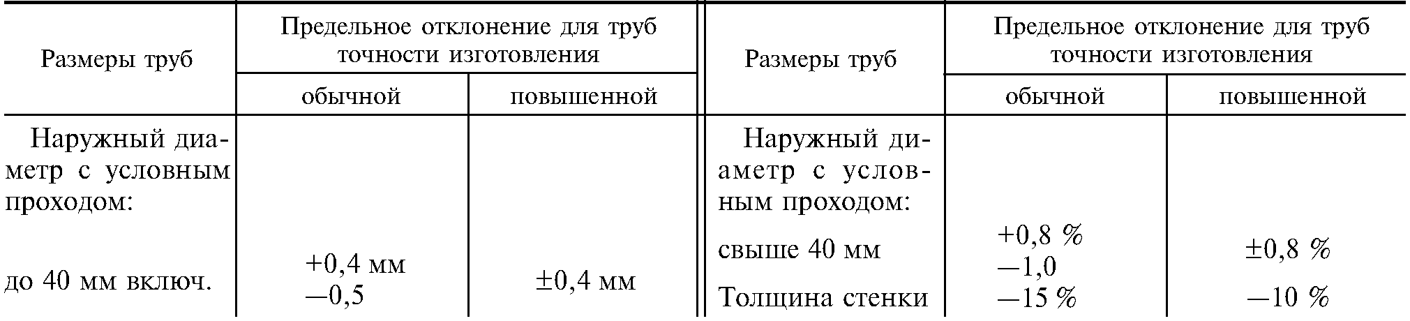
1.3. Maximum deviations in pipe sizes should not exceed those indicated in the table. 3.
Table 3
| Pipe sizes | Limit deviations for manufacturing precision pipes |
|
| ordinary | increased |
|
| Outer diameter with nominal bore: | ||
| up to 40 mm incl. | 0.4 mm | 0.4 mm |
| 0.5 mm | 0.4 mm |
|
| Over 40 mm | 0,8 % | 0,8 % |
| 1,0 % | 0,8 % |
|
| Wall thickness | 15 % | 10 % |
Notes:
1. The maximum deviation in the positive direction for wall thickness is limited by the maximum deviations for the mass of the pipes.
2. Pipes of standard manufacturing precision are used for water supply, gas pipelines and heating systems. Pipes with increased manufacturing precision are used for parts of water and gas pipeline structures.
1.4. Maximum deviations in the mass of pipes should not exceed + 8%.
At the request of the consumer, maximum deviations in mass should not exceed:
7.5% - for the party;
10% - for a separate pipe.
(Changed edition, Amendment No. 2, 5).
1.5. The curvature of pipes per 1 m length should not exceed:
2 mm - with nominal bore up to 20 mm inclusive;
1.5 mm - with a nominal bore over 20 mm.
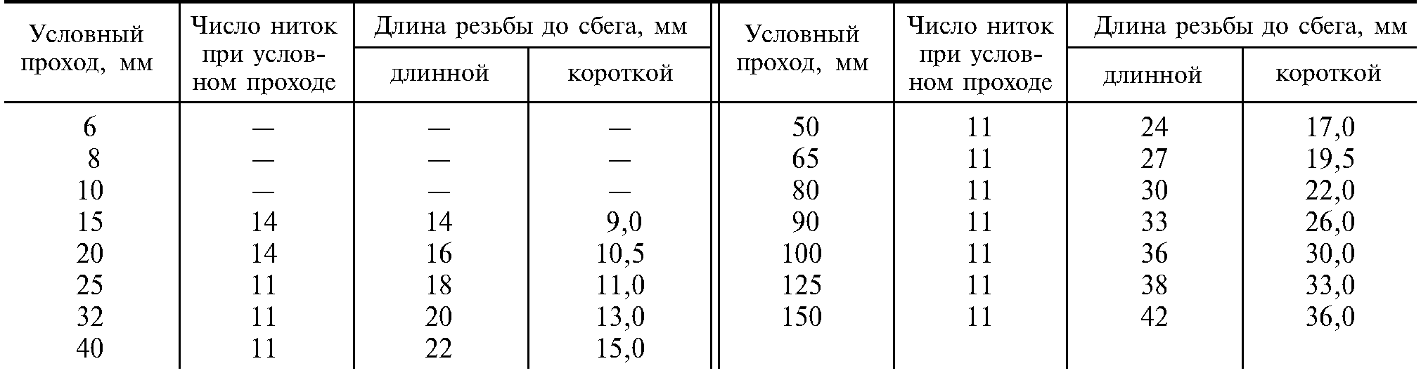
1.6. Pipe threads can be long or short. The thread requirements must correspond to those indicated in the table. 4.
Table 4
| Conditional bore, mm | Thread length before running away | Conditional bore, mm | Number of currents at nominal flow | Thread length before running away |
|||
| long | short | long | short |
||||
| 17,0 |
|||||||
| 19,5 |
|||||||
| 22,0 |
|||||||
| 26,0 |
|||||||
| 10,5 | 30,0 |
||||||
| 11,0 | 33,0 |
||||||
| 13,0 | 36,0 |
||||||
| 15,0 | |||||||
1.7. Pipes with a nominal bore of 6, 8, 10, 15 and 20 mm are wound into coils at the consumer’s request.
Examples of symbols
An ordinary pipe, non-galvanized, of normal manufacturing precision, of unmeasured length, with a nominal bore of 20 mm, a wall thickness of 2.8 mm, without threads and without a coupling:
Pipe 20 2, GOST 3262-75
The same with the coupling:
Pipe M-20 2, GOST 3262-75
The same, measured length, with thread:
Pipe R-20 2, - 4000 GOST 3262-75
The same, with zinc coating, of unmeasured length, with thread:
Pipe Ts-R-20 2, GOST 3262-75
The same, with zinc coating, custom length, with thread:
Pipe Ts-R-20 2, - 4000 GOST 3262-75
For pipes for rolling threads, the letter N is indicated in the symbol after the word “pipe”.
For pipes with long threads, the letter D is indicated after the word “pipe” in the symbol.
For pipes with increased manufacturing precision, the letter P is indicated in the symbol after the size of the nominal bore.
(Changed edition, Amendment No. 1).
2. TECHNICAL REQUIREMENTS
2.1. Pipes are manufactured in accordance with the requirements of this standard and according to technological regulations approved in the prescribed manner, from steels in accordance with GOST 380-88 and GOST 1050-88 without standardization of mechanical properties and chemical composition.
Pipes for parts of water supply and gas pipeline structures are made of steel in accordance with GOST 1050-88.
2.2. At the request of the consumer, the ends of pipes to be welded, with a wall thickness of 5 mm or more, must be chamfered at an angle of 35-40° to the end of the pipe. In this case, an end ring 1 - 3 mm wide should be left.
At the request of the consumer, on ordinary and reinforced pipes with a nominal bore of more than 10 mm, threads are applied to both ends of the pipe.
2.1; 2.2. (Changed edition, Amendment No. 3, 4).
2.3. At the request of the consumer, pipes are equipped with couplings manufactured in accordance with GOST 8944-75, GOST 8954-75, GOST 8965-75 and GOST 8966-75 at the rate of one coupling for each pipe.
(Changed edition, Amendment No. 3).
2.4. Cracks, spots, swellings and declines are not allowed on the surface of the pipes.
Delamination is not allowed at the ends of the pipes.
Individual dents, rippling, scratches, traces of stripping and other defects caused by the production method are allowed if they do not exceed the wall thickness minimum dimensions, as well as a layer of scale that does not interfere with inspection.
On pipes made by furnace welding, it is allowed to reduce the outer diameter to 0.5 mm at the seam if there is a gentle thickening in this place along the inner diameter of no more than 1.0 mm.
(Changed edition, Amendment No. 3, 4).
2.5. At the request of the consumer, on pipes with a nominal bore of 20 mm or more, the burr on the inner surface of the pipe seam must be cut off or flattened, and the height of the burr or its traces should not exceed 0.5 mm.
At the request of the consumer, on pipes with a nominal bore of more than 15 mm, manufactured by furnace welding and hot reduction, a gentle thickening with a height of no more than 0.5 mm is allowed on the inner surface of the pipes in the weld area.
(Changed edition, Amendment No. 2, 3, 4, 5, 6).
2.6. The ends of the pipes must be cut at right angles. The allowed end bevel is no more than 2°. The remaining burrs should not exceed 0.5 mm. When removing burrs, the formation of blunting (rounding) of the ends is allowed. It is allowed to cut pipes in the mill line.
By agreement between the manufacturer and the consumer, burrs up to 1 mm are allowed on pipes with a nominal bore of 6-25 mm, manufactured by furnace welding.
(Changed edition, Amendment No. 4, 6).
2.7. Galvanized pipes must have a continuous zinc coating over the entire surface with a thickness of at least 30 microns. The absence of zinc coating on the ends and threads of pipes is allowed.
On the surface of galvanized pipes, bubbles and foreign inclusions (hardzinc, oxides, sintered mixture), and peeling of the coating from the base metal are not allowed.
Individual flux spots and traces of pipes being caught by lifting devices, roughness and minor local deposits of zinc are allowed.
It is allowed to correct individual non-galvanized areas by 0.5% outer surface pipes according to GOST 9.307-89.
(Changed edition, Amendment No. 3, 4).
2.8. Pipes must withstand hydraulic pressure:
2.4 MPa (25 kgf/cm 2) - pipes, ordinary and light;
3.1 MPa (32 kgf/cm 2) - reinforced pipes.
At the request of the consumer, the pipes must withstand hydraulic pressure of 4.9 MPa (50 kgf/cm2)
(Changed edition, Amendment No. 2, 3, 5).
2.9. Pipes with a nominal bore up to 40 mm inclusive must withstand the bend test around a mandrel with a radius equal to 2.5 outer diameters, and with a nominal bore of 50 mm - on a mandrel with a radius equal to 3.5 outer diameters.
At the request of the consumer, pipes must withstand the distribution test:
for pipes with a nominal bore from 15 to 50 mm - no less than 7%;
for pipes with a nominal bore of 65 or more - no less than 4%.
At the request of the consumer, pipes must withstand the flattening test to a distance between the flattened surfaces equal to 2/3 of the outer diameter of the pipes.
(Changed edition, Amendment No. 2, 3, 5).
2.10. At the request of the consumer, the mechanical properties of pipes for parts of water supply and gas pipeline structures must comply with GOST 1050-88.
2.11. Pipe threads must be clean, without flaws or burrs and comply with GOST 6357-81, accuracy class B.
Pipes with cylindrical threads are used when assembling with seals.
2.10; 2.11. (Changed edition, Amendment No. 3, 4).
2.12. At the seam, blackness on the threads is allowed if the reduction in the normal height of the thread profile does not exceed 15%, and at the request of the consumer does not exceed 10%.
Threads with torn (for cut) or incomplete (for rolled) threads are allowed on threads, provided that their total length does not exceed 10% of the required thread length, and at the request of the consumer does not exceed 5%.
(Changed edition, Amendment No. 2, 3, 5).
2.13. On a thread, it is allowed to reduce the useful length of the thread (without running) up to 15% compared to that indicated in the table. 4, and at the consumer’s request up to 10%.
(Changed edition, Amendment No. 2, 3, 5).
2.14. Threading on galvanized pipes is carried out after galvanizing.
2.15. (Deleted, Amendment No. 3).
2.16. At the request of the consumer, pipe welds are subjected to testing using non-destructive methods.
(Changed edition, Amendment No. 5).
3. ACCEPTANCE RULES
3.1. Pipes are accepted in batches. The batch must consist of pipes of the same size, the same brand and be accompanied by one quality document in accordance with GOST 10692-80 with the addition for pipes intended for the manufacture of parts for water supply and gas pipeline structures, made of steel in accordance with GOST 1050-88: chemical composition and mechanical properties of steel in accordance with the document on the quality of the workpiece manufacturer.
The batch weight is no more than 60 tons.
(Changed edition, Amendment No. 3, 4).
3.2. Each pipe in the batch is subjected to inspection of the surface, dimensions and curvature.
It is allowed to use statistical control methods in accordance with GOST 18242-72 c normal level. Control plans are established by agreement between the manufacturer and the consumer.
The outer diameter of the pipes is checked at a distance of at least 15 mm from the end of the pipe.
(Changed edition, Amendment No. 3, 4, 5).
3.3. To control the parameters of the thread, to test for expansion, flattening, bending, the height of the internal burr, the remains of burrs, the right angle and the chamfer angle (for pipes with beveled edges), mechanical properties, no more than 1%, but not less than two pipes from the batch are selected, and for pipes manufactured by continuous furnace welding - two pipes per batch.
(Changed edition, Amendment No. 3, 4).
3.4. All pipes are subject to weight control.
(Changed edition, Amendment No. 3).
3.5. Each pipe is subjected to hydraulic pressure testing. With 100% quality control of the weld using non-destructive methods, hydraulic pressure testing may not be carried out. At the same time, the ability of the pipes to withstand the test hydraulic pressure is guaranteed.
(Changed edition, Amendment No. 6).
3.6. To check the thickness of the zinc coating on the outer surface and in accessible places on the inner surface, two pipes from the batch are selected.
(Changed edition, Amendment No. 2).
3.7. If unsatisfactory test results are obtained for at least one of the indicators, a repeat test is carried out on a double sample.
The results of repeated tests apply to the entire batch.
4. TEST METHODS
4.1. For quality control, one sample is cut from each selected pipe for each type of test.
The tensile test is carried out according to GOST 10006-80. Instead of tensile testing, it is allowed to control mechanical properties using non-destructive methods.
4.2. The surface of the pipes is inspected visually.
4.3. Hydraulic test carried out according to GOST 3845-75 with exposure under test pressure for at least 5 s.
4.4. The bend test is carried out according to GOST 3728-78. Galvanized pipes are tested before coating.
(Changed edition, Amendment No. 3).
4.4a. The expansion test is carried out according to GOST 8694-75 on a conical mandrel with a cone angle of 6°.
Testing on a mandrel with a taper angle of 30° is permitted.
(Changed edition, Amendment No. 3, 4).
4.4b. The flattening test is carried out according to GOST 8695-75.
(Changed edition, Amendment No. 3).
4.4v. Weld inspection is carried out using non-destructive methods according to regulatory and technical documentation.
(Introduced additionally, Amendment No. 3).
4.5. The thickness of the zinc coating on the outer surface and in accessible places on the inner surface is controlled according to GOST 9.301-86 and GOST 9.302-88, as well as with devices of the MT-41NTs, MTZON or Impulse type according to the normative and technical documentation.
4.6. The thread is checked using thread ring gauges in accordance with GOST 2533-88 (third accuracy class).
In this case, the screw-in of the no-go ring gauge onto the thread should be no more than three turns.
(Changed edition, Amendment No. 3, 4).
4.7. The curvature of the pipes is controlled using a straight edge in accordance with GOST 8026-92 and a set of probes in accordance with TU 2-034-225-87.
(Changed edition, Amendment No. 3, 5).
4.8. The right angle of the pipe ends is controlled with a 90° square measuring 160x100 mm, class 3 GOST 3749-77, plate probes set 4 TU 2-034-225-87 or an inclinometer GOST 5378-88. The bevel angle of the chamfer is controlled with a protractor according to GOST 5378-88.
(Changed edition, Amendment No. 3, 6).
4.9. The outer diameter is checked using smooth micrometers in accordance with GOST 6507-90, clamp gauges in accordance with GOST 2216-84 or GOST 18362-73.
The wall thickness, the height of the internal burr and the height of the burrs are measured with a micrometer according to GOST 6507-90 or a wall gauge according to GOST 11358-89 from both ends of the pipe.
The length of the pipes is measured with a tape measure according to GOST 7502-89. Threads are controlled with gauges in accordance with GOST 2533-88.
The mass of a batch of pipes is controlled on scales of no more than 10 tons with a division value of no more than 20 kg.
(Changed edition, Amendment No. 3, 4, 5, 6).
4.10. Weld inspection is carried out using non-destructive methods according to technical documentation.
(Introduced additionally, Amendment No. 4).
5. LABELING, PACKAGING, TRANSPORTATION AND STORAGE
5.1. Labeling, packaging, transportation and storage are carried out in accordance with GOST 10692-80 with addition.
5.1.1. Pipe threads must be protected from mechanical damage and corrosion by lubricant according to the regulatory and technical documentation.
Sec. 5. (Changed edition, Amendment No. 3).
INFORMATION DATA
1. DEVELOPED AND INTRODUCED by the USSR Ministry of Ferrous Metallurgy
DEVELOPERS
V. I. Struzhok, Ph.D. tech. sciences, V. M. Vorona, Ph.D. tech. sciences, Yu. M. Mironov, Ph.D. tech. nook, A. I. Postolova
2. APPROVED AND ENTERED INTO EFFECT by Resolution of the USSR State Committee for Standards dated 09.11.75 No. 2379
3. Inspection frequency 5 years
4. INSTEAD GOST 3262-62
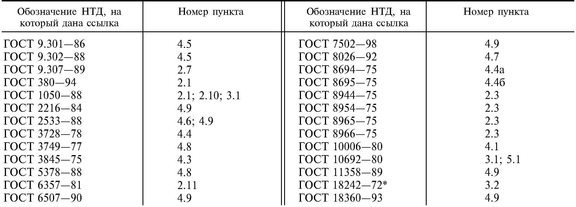
5. REFERENCE REGULATIVE AND TECHNICAL DOCUMENTS
| Item number |
|
| GOST 9.301-86 | |
| GOST 9.302-88 | |
| GOST 9.307-89 | |
| GOST 380-88 | |
| GOST 1050-88 | 2.1, 2.10, 3.1 |
| GOST 2216-84 | |
| GOST 8694-75 | 4.4a |
| GOST 8695-75 | 4.4b |
| GOST 8944-75 | |
| GOST 8954-75 | |
| GOST 8965-75 | |
| GOST 8966-75 | |
| GOST 10006-80 | |
| GOST 10692-80 | |
| GOST 11358-89 | |
| GOST 18242-72 | |
| GOST 18363-73 | |
| TU 2-034-225-88 | 4.7, 4.8 |
6. Reissue (May 1994) with Amendments No. 1, 2, 3, 4, 5, 6, approved in November 1977, December 1978, January 1987, May 1988, November 1989. , November 1991 (IUS 1-78, 2-79, 4-87, 8-88, 2-90, 2-92)
Water-supply and gas-supply steel pipes. Specifications
GOST 3262-75
OKP 13 8500, OKP 13 8501
Date of introduction 01/01/77
This standard applies to non-galvanized and galvanized steel welded pipes with cut or rolled cylindrical threads and without threads, used for water and gas pipelines, heating systems, as well as for parts of water and gas pipeline structures.
(Changed edition, Amendment No. 2, 3, 5).
1. ASSORTMENT
1.1. Pipes are manufactured according to the dimensions and weight given in table. 1.
At the consumer's request, light series pipes intended for thread rolling are manufactured according to the dimensions and weight given in table. 2.
(Changed edition, Amendment No. 1, 3).
1.2. The length of the pipe is made from 4 to 12 m:
measured or multiple measured length with an allowance for each cut of 5 mm and a longitudinal deviation over the entire length plus 10 mm;
of unmeasured length.
By agreement between the manufacturer and the consumer, up to 5% of pipes with a length of 1.5 to 4 m are allowed in a batch of unmeasured pipes.
Table 1
Table 2
Notes:
1. For threads made by rolling on a pipe, it is allowed to reduce its internal diameter by up to 10% along the entire length of the thread.
2. The mass of 1 m of pipes is calculated at a steel density of 7.85 g/cm 3 . Galvanized pipes are 3% heavier than non-galvanized pipes.
1.3. Maximum deviations in pipe sizes should not exceed those indicated in the table. 3.
Table 3
Notes:
1. The maximum deviation in the positive direction for wall thickness is limited by the maximum deviations for the mass of the pipes.
2. Pipes of standard manufacturing precision are used for water supply, gas pipelines and heating systems. Pipes with increased manufacturing precision are used for parts of water and gas pipeline structures.
1.4. Maximum deviations in the mass of pipes should not exceed +8%.
At the request of the consumer, maximum deviations in mass should not exceed:
7.5% - for the party;
10% - for a separate pipe.
(Changed edition, Amendment No. 2, 5).
1.5. The curvature of pipes per 1 m length should not exceed:
2 mm - with nominal bore up to 20 mm inclusive;
1.5 mm - with a nominal bore over 20 mm.
1.6. Pipe threads can be long or short. The thread requirements must correspond to those indicated in the table. 4.
Table 4
1.7. Pipes with a nominal bore of 6, 8, 10, 15 and 20 mm are wound into coils at the consumer’s request.
EXAMPLES OF CONDITIONAL NOTATIONS
An ordinary pipe, non-galvanized, of normal manufacturing precision, of unmeasured length, with a nominal bore of 20 mm, a wall thickness of 2.8 mm, without threads and without a coupling:
Pipe 20 -2.8 TOST 3262-75
The same with the coupling:
Pipe M-20 -2.8 TOST 3262-75
The same, measured length, with thread:
Pipe R-20 2.8-4000 TOST 3262-75
The same, with zinc coating, of unmeasured length, with thread:
Pipe Ts-R-20 -2.8 TOST 3262-75
The same, with zinc coating, custom length, with thread:
Pipe Ts-R-20 -2.8-4000 TOST 3262-75
For pipes for rolling threads, the letter N is indicated in the symbol after the word “pipe”.
For pipes with long threads, the letter D is indicated after the word “pipe” in the symbol.
For pipes with increased manufacturing precision, the letter P is indicated in the symbol after the size of the nominal bore.
(Changed edition, Amendment No. 1).
2. TECHNICAL REQUIREMENTS
2.1. Pipes are manufactured in accordance with the requirements of this standard and according to technological regulations approved in the prescribed manner, from steels in accordance with GOST 380 and GOST 1050 without standardization of mechanical properties and chemical composition.
Pipes for parts of water supply and gas pipeline structures are made of steel in accordance with GOST 1050.
2.2. At the request of the consumer, the ends of pipes to be welded with a wall thickness of 5 mm or more must be chamfered at an angle of 35-40° to the end of the pipe. In this case, an end ring 1-3 mm wide should be left.
At the request of the consumer, on ordinary and reinforced pipes with a nominal bore of more than 10 mm, threads are applied to both ends of the pipe.
2.1, 2.2. (Changed edition, Amendment No. 3, 4).
2.3. At the request of the consumer, pipes are equipped with couplings manufactured in accordance with GOST 8944, GOST 8954, GOST 8965 and GOST 8966, at the rate of one coupling for each pipe.
(Changed edition, Amendment No. 3).
2.4. Cracks, spots, swellings and declines are not allowed on the surface of the pipes.
Delamination is not allowed at the ends of the pipes.
Individual dents, rippling, scratches, traces of stripping and other defects caused by the production method are allowed, if they do not take the wall thickness beyond the minimum dimensions, as well as a layer of scale that does not interfere with inspection.
On pipes made by furnace welding, it is allowed to reduce the outer diameter to 0.5 mm at the seam if there is a gentle thickening in this place along the inner diameter of no more than 1.0 mm.
(Changed edition, Amendment No. 3, 4).
2.5. At the request of the consumer, on pipes with a nominal bore of 20 mm or more, the burr on the inner surface of the pipe seam must be cut off or flattened, and the height of the burr or its trace must not exceed 0.5 mm.
At the request of the consumer, on pipes with a nominal bore of more than 15 mm, manufactured by furnace welding and hot reduction, a gentle thickening with a height of no more than 0.5 mm is allowed on the inner surface of the pipes in the weld area.
(Changed edition, Amendment No. 2, 3, 4, 5, 6).
2.6. The ends of the pipes must be cut at right angles. An end bevel of more than 2° is allowed. The remaining burrs should not exceed 0.5 mm. When removing burrs, blunting (rounding) of the ends is allowed. It is allowed to cut pipes in the mill line.
By agreement between the manufacturer and the consumer, burrs up to 1 mm are allowed on pipes with a nominal bore of 6–25 mm, manufactured by furnace welding.
(Changed edition, Amendment No. 4, 6).
2.7. Galvanized pipes must have a continuous zinc coating over the entire surface with a thickness of at least 30 microns. The absence of zinc coating on the ends and threads of pipes is allowed.
On the surface of galvanized pipes, bubbles and foreign inclusions (hardzinc, oxides, sintered mixture), and peeling of the coating from the base metal are not allowed.
Individual flux spots and traces of pipes being caught by lifting devices, roughness and minor local deposits of zinc are allowed.
It is allowed to correct individual non-galvanized areas on 0.5% of the outer surface of the pipe in accordance with GOST 9.307.
(Changed edition, Amendment No. 3, 4).
2.8. Pipes must withstand hydraulic pressure:
2.4 MPa (25 kgf/cm 2) - ordinary and light pipes;
3.1 MPa (32 kgf/cm 2) - reinforced pipes.
At the request of the consumer, the pipes must withstand a hydraulic pressure of 4.9 MPa (50 kgf/cm2).
2.9. Pipes with a nominal bore up to 40 mm inclusive must withstand the bend test around a mandrel with a radius equal to 2.5 outer diameters, and with a nominal bore of 50 mm - on a mandrel with a radius equal to 3.5 outer diameters.
At the request of the consumer, pipes must withstand the distribution test:
for pipes with a nominal bore from 15 to 50 mm - no less than 7%;
for pipes with a nominal bore of 65 mm or more - no less than 4%.
At the request of the consumer, pipes must withstand the flattening test to a distance between flattened surfaces equal to 2/3 of the outer diameter of the pipes.
2.8, 2.9. (Changed edition, Amendment No. 2, 3, 5).
2.10. At the request of the consumer, the mechanical properties of pipes for parts of water supply and gas pipeline structures must comply with GOST 1050.
2.11. Pipe threads must be clean, without flaws or burrs and comply with GOST 6357, accuracy class B.
Pipes with cylindrical threads are used when assembling with seals.
2.10, 2.11. (Changed edition, Amendment No. 3, 4).
2.12. At the seam, blackness on the threads is allowed if the reduction in the normal height of the thread profile does not exceed 15%, and at the request of the consumer does not exceed 10%.
Threads with broken (for cut) or incomplete (for rolled) threads are allowed on threads, provided that their total length does not exceed 10% of the required thread length, and according to consumer requirements does not exceed 5%.
2.13. On a thread, it is allowed to reduce the useful length of the thread (without running) up to 15% compared to that indicated in the table. 4, and at the consumer’s request - up to 10%.
2.12, 2.13. (Changed edition, Amendment No. 2, 3, 5).
2.14. Threading on galvanized pipes is carried out after galvanizing.
2.15. (Deleted, Amendment No. 3).
2.16. At the request of the consumer, pipe welds are subjected to testing using non-destructive methods.
(Changed edition, Amendment No. 5).
3. ACCEPTANCE RULES
3.1. Pipes are accepted in batches. The batch must consist of pipes of the same size, the same grade of steel and be accompanied by one quality document in accordance with GOST 10692 with the addition for pipes intended for the manufacture of parts for water supply and gas pipeline structures, made of steel in accordance with GOST 1050; chemical composition and mechanical properties of steel - in accordance with the document on the quality of the manufacturer of the workpiece.
Lot weight: no more than 60 tons.
(Changed edition, Amendment No. 3, 4).
3.2. Each pipe in the batch is subjected to inspection of the surface, dimensions and curvature.
It is allowed to use statistical control methods in accordance with GOST 18242 with a normal level. Control plans are established by agreement between the manufacturer and the consumer.
The outer diameter of the pipes is checked at a distance of at least 15 mm from the end of the pipe.
(Changed edition, Amendment No. 3, 4, 5).
3.3. To control the parameters of the thread, to test for expansion, flattening, bending, the height of the internal burr, the remains of burrs, the right angle and the chamfer angle (for pipes with beveled edges), mechanical properties, no more than 1%, but not less than two pipes from the batch, are selected, and for pipes manufactured by continuous furnace welding - two pipes per batch.
(Changed edition, Amendment No. 3, 4).
3.4. All pipes are subject to weight control.
(Changed edition, Amendment No. 3).
3.5. Each pipe is subjected to hydraulic pressure testing. With 100% quality control of the weld using non-destructive methods, hydraulic pressure testing may not be carried out. At the same time, the ability of the pipes to withstand the test hydraulic pressure is guaranteed.
(Changed edition, Amendment No. 6).
3.6. To check the thickness of the zinc coating on the outer surface and in accessible places on the inner surface, two pipes from the batch are selected.
(Changed edition, Amendment No. 2).
3.7. If unsatisfactory test results are obtained for at least one of the indicators, repeated tests are carried out on a double sample.
The results of repeated tests apply to the entire batch.
4. TEST METHODS
4.1. For quality control, one sample is cut from each selected pipe for each type of test.
The tensile test is carried out in accordance with GOST 10006. Instead of the tensile test, it is allowed to control the mechanical properties by non-destructive methods.
4.2. Inspection of the pipe surface is carried out visually.
4.3. Hydraulic testing is carried out in accordance with GOST 3845 with exposure under test pressure for at least 5 s.
4.4. The bend test is carried out according to GOST 3728. Galvanized pipes are tested before coating.
(Changed edition, Amendment No. 3).
4.4a. The expansion test is carried out according to GOST 8694 on a conical mandrel with a cone angle of 6°.
Testing on a mandrel with a taper angle of 30° is allowed.
(Changed edition, Amendment No. 3, 4).
4.46. The flattening test is carried out according to GOST 8695.
(Changed edition, Amendment No. 3).
4.4v. Weld inspection is carried out using non-destructive methods in accordance with regulatory documentation.
(Introduced additionally, Amendment No. 3).
4.5. The thickness of the zinc coating on the outer surface and in accessible places on the inner surface is controlled according to GOST 9.301 and GOST 9.302, as well as with devices of the MT-41NTs, MTZON or Impulse types according to regulatory documentation.
4.6. The thread is checked using thread ring gauges in accordance with GOST 2533 (third accuracy class).
In this case, the screw-in of the no-go ring gauge onto the thread should be no more than three turns.
(Changed edition, Amendment No. 3, 4).
4.7. The curvature of the pipes is controlled using a straight edge in accordance with GOST 8026 and a set of feelers according to ND.
(Changed edition, Amendment No. 3, 5).
4.8. The right angle of the pipe ends is controlled with a 90° square measuring 160-100 mm, class 3 according to GOST 3749, plate probes set 4 according to ND or a protractor according to GOST 5378. The bevel angle is controlled with a protractor according to GOST 5378.
(Changed edition, Amendment No. 3, 6).
4.9. The outer diameter is checked using smooth micrometers in accordance with GOST 6507, clamp gauges in accordance with GOST 2216 or GOST 18360.
The wall thickness, the height of the internal burr and the height of the burrs are measured with a micrometer according to GOST 6507 or a wall gauge according to GOST 11358 at both ends of the pipe.
The length of the pipes is measured with a tape measure in accordance with GOST 7502. The threads are controlled with gauges in accordance with GOST 2533.
The mass of a batch of pipes is controlled on scales of no more than 10 tons with a division value of no more than 20 kg.
(Changed edition, Amendment No. 3, 4, 5, 6).
4.10. Weld inspection is carried out using non-destructive methods according to technical documentation.
(Introduced additionally, Amendment No. 4).
5. LABELING, PACKAGING, TRANSPORTATION AND STORAGE
5.1. Labeling, packaging, transportation and storage are carried out in accordance with GOST 10692 with addition.
5.1.1. Pipe threads must be protected from mechanical damage and corrosion by lubricant in accordance with regulatory documentation.
Sec. 5. (Changed edition, Amendment No. 3).
INFORMATION DATA
1. DEVELOPED AND INTRODUCED by the Ministry of Ferrous Metallurgy of the USSRDEVELOPERS
V. I. Struzhok, Ph.D. tech. sciences; V. M. Vorona, Ph.D. tech. sciences; Yu. M. Mironov, Ph.D. tech. sciences; A. I. Postolova
2. APPROVED AND ENTERED INTO EFFECT by Resolution of the USSR State Committee on Standards dated September 11, 1975 No. 2379
3. Inspection frequency - 5 years
4. INSTEAD GOST 3262-62
5. REFERENCE REGULATIVE AND TECHNICAL DOCUMENTS
6. Validity restrictions were removed by Gosstandart Decree No. 1726 dated November 12, 1991
7. EDITION with Amendments No. 1, 2, 3, 4, 5, 6, approved January 1987, May 1988, November 1989, November 1991 2-90, 2-92)
In the territory Russian Federation GOST R 50779.71-99 is valid.


