We bring to your attention a simple, high-quality
six-channel digital volume control
. The regulator is assembled on a TDA7448 chip manufactured by the European company STMicroelectronics. This microcircuit has a digital I2C interface. To control via this interface, a common, cheap, high-speed RISC microcontroller from Microchip PIC16F873 was used (can be replaced with PIC16F873A, PIC16F876, PIC16F876A).Developers of microcontroller devices from Microchip have the unique ability to easily connect multiple encoders without additional wiring. This made it possible to implement a rather unusual concept for the device.
Structurally, the circuit consists of two components: a microcontroller control unit
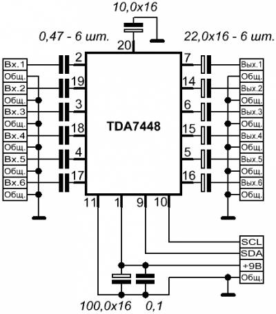
And the regulator unit on TDA7448.
The regulator is intended to be used in 5.1 format systems. This assumes the following channels: front (left and right), rear (left and right), center and subwoofer. To control these channels, 4 encoders are used. The volume and balance mode for the front and rear can be switched with the "volume/balance" button. There are also “Mute” and “StandBy” buttons. There is also a separate StandBy line, which can be used to hardware disable amplifiers. A special mode is “Master volume”. The transition to this mode is carried out using a button on a reserved line. In this mode, all encoders operate in parallel, i.e. change the volume levels evenly across all channels (lines). The "overall volume" parameter does not have any specific numerical measurement, because Each channel is set to its own volume level. Adjusting the "overall volume" only simultaneously decreases or increases all channels.
To visualize the direction of regulation in this mode, the indicator shows the name of the “Master volume” mode on the top line, and animated icons on the bottom line<<<<< или >>>>>.

All of the above control functions can be performed via any remote control in RC5 format (from Philips household appliances).
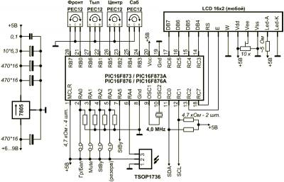
Printed circuit boards are made of single-sided foil PCB using the LUT method, but can easily be made on circuit boards. Files of board drawings in Sprint Layout format are at the end of the article. Below is a drawing and photograph of the assembled printed circuit board of the microcontroller control unit.

The values of resistances and capacitors may differ from those indicated in the diagram by 20%.
The indicator has 2 lines of 16 symbols. They are produced by many different companies and they contain different microcircuits: HD44780 (HITACHI), KS0066 (SAMSUNG), KB1013VG6 (ANGSTREM) and others.
The IR receiver TSOP1736 (Vishay) can be replaced with SFH-506 (Siemens), TFMS5360 (Temic), ILM5360 (Integral software).
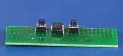
The TDA7448 chip is made in a surface-mount package, but has a fairly wide lead pitch (1.27 mm) and is easily soldered with a sharpened soldering iron. Below is a drawing and photograph of the assembled printed circuit board of the regulator unit on the TDA7448.
If you are tired of turning the volume control knob and want to try something “modern”, then you can adjust the volume with buttons, for which you can easily assemble the proposed regulator.
The regulator circuit is very simple and does not require configuration; moreover, it takes up only a little more space than a variable resistor, and the board can be placed anywhere.
Table 1 Main technical characteristics
table 2 Volume control steps
Regulator circuit:
Picture 1 - Schematic diagram regulator
Table 3 List of elements
Element Denomination Quantity 4.7 µF × 50 V 22 µF ×25 V 100 µF × 25 V Any buttons without fixation TC9153AP or KA2250
The KA2250 and TC9153AP microcircuits are completely interchangeable, their pinouts and characteristics are the same. I connected a dial indicator from an old tape recorder to pin 8 of the DA1 “volume level indication” microcircuit through an additional resistor with a resistance of 1 kOhm (it should be selected based on the deviation of the instrument needle to the full scale when the control is set to maximum volume). The "-" pin of the indicator is connected to the common wire of this device. Each step of volume adjustment increases (decreases) the indicator reading by approximately 100 μA. A photo of the assembled regulator is shown in Figure 2:
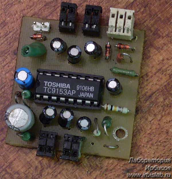
Figure 2
The advantages of using such a regulator: Synchronous adjustment of both channels. Unlike a conventional variable resistor, this regulator has no noise during adjustment. It is also not subject to degradation, i.e. deterioration in the quality of adjustment due to wear of the conductive surface and the variable resistor motor. Of course, buttons are also a mechanical element, but they only control, while an electric sound signal often directly passes through a conventional variable resistor in ultrasonic circuits.
Minuses: Don't turn up the volume sharply, but that might be for the better, the amplifier will be more intact. Also: these microcircuits do not have memory; when the power is turned off, the microcircuit is reset to average level volume, which is actually rather a positive side - there is no “blow to the ears” when turned on.
Attention: The maximum input voltage of the TC9153AP and KA2250 microcircuits is 4 V peak value, i.e. approximately 2.8 V effective. This level, in order to avoid failure of the microcircuit, cannot be exceeded!
It is optimal to use it this way: Linear output of a computer sound card, or DVD > tone block or equalizer > volume control > power amplifier > speaker system.
Attention: Not allowed use a regulator in power circuits, for example: Power amplifier > volume control > speaker system.
With my own hands I assembled several of these regulators on microcircuits of both types, and they all worked right away. A small practical note: if, when setting the control to the minimum volume (-64 dB), the sound is still audible, then you can get rid of this by increasing the capacitance of capacitor C8 to approximately 1000 µF.
It takes a lot of effort to keep the regulator from working. The reasons for the malfunction may be different, but the main ones are: short circuits on the board, poor installation, and the use of faulty radio elements. I have never come across defective microcircuits.
Copyright Laboratory of Irbis - Soft steps to the heights of knowledge and skill All rights reserved.
Digital volume control on DS1669
The circuit is based on a ready-made digital volume control DS1669.
This chip made it possible to simplify push-button sound control to the limit, and really, how much easier is it? The only external components are buttons and a power supply capacitor. Nevertheless, the microcircuit has performed well.
DS1669 o provides 64 positions of equal reference points throughout the entire resistance range
The digital potentiometer can be controlled either manually using buttons or from a microcontroller. When the regulator's power is turned off, the position of the digital rheostat is stored in non-volatile memory built into the microcircuit. After turning on the power, information about the previous position of the regulator slide is retrieved from memory.
The supply voltage of the microcircuit is 4.5 - 8 volts.
IN standard scheme n Pressing one button moves the contact up one position, pressing the second button moves the contact down one position.
The standard connection diagram looks like this:
Also the microcircuitDS1669 allows you to organize control using one button. Each time you press the button, the slider moves up one of 64 positions, and when it reaches the top position, it moves to the bottom.
But this circuit is more convenient to use for voltage regulation, for examplefor controlling the contrast of liquid crystal indicators (LCDs) The figure below shows a circuit for controlling the contrast for LCDs using a one-button control of a digital potentiometer DS 1669. The liquid crystal module is powered by 5 Volts. The same voltage is supplied to DS 1669, whose resistance is 10 kOhm. The current collector terminal is connected directly to the power input.The use of a digital potentiometer makes it possible to reduce the size of the device, significantly increase durability and transfer control to the system microcontroller.

Another option for turning on a digital controller using transistors instead of control buttons. In this case, the control device is a controller or other logical circuits.The frequency band of the DS1669 digital potentiometer is determined by its rating: for a resistance of 10 kOhm the frequency band is 1 MHz, for a resistance of 50 kOhm - 200 kHz, for a resistance of 100 kOhm - 100 kHz.

.
There are similar chips with non-volatile memory, but they are several times more expensive and, as a rule, single-channel (mono). The most common chip is the DS1804, which is a 100-step “variable resistor” (Fig. 5a).
Since the microcircuit is expensive, and stereo equipment requires 2 such microcircuits, it makes sense to use it in conjunction with a cheaper electronic stereo regulator, as shown in Fig. 56. But at the same time, the sound quality deteriorates: the parameters of the “variable resistor” DS1804 are much better than those of any electronic regulator (this also applies to all other DALLAS chips).
True, only a specialist can notice this “deterioration”, and only with special instruments. So decide for yourself what is more important - slightly higher sound quality or an affordable price. The microcircuits are available in 8-pin packages such as DIP, SOIC, pSOP and Flip Chip Package, the resistance of the “variable resistor” can be equal to 10, 50 and 100 kOhm (it is indicated by a 3-digit number at the end of the name, for example, DS1804-050 - with 50 - kilo-ohm resistor).
The cutoff frequency of the signal (at a level of -3 dB) at the terminals of the “resistor” is 1 MHz for a microcircuit with a 10 kOhm resistor, 200 kHz for 50 kOhm and 100 kHz for 100 kOhm. The voltages at both “extreme” terminals of the resistor can be any, but should not exceed the supply voltage by more than 0.5 V.
The microcircuit is controlled via a 3-wire interface:
- CS input - enabled/disabled (respectively, by level “0V1”);
- input U/D - direction of volume change (at “1” - volume increases);
- input INC - clock pulses.
After selecting the optimal volume, it is advisable to set the CS input level to “1” (the current consumed by the microcircuit will decrease). If at this moment the INC input is “1st”, the information is stored in the non-volatile memory of the microcircuit (after turning the power off and on, this volume will be set).
The memory write cycle lasts about 10 ms. When the INC input is "0", the information is not saved. You cannot abuse writing to memory: the life of the microcircuit is only 50,000 write cycles (for daily operation for 10 years, you can change the recorded information in memory no more than 14 times a day).
Here it should be noted that all “normal” memory chips have a resource 20 times greater. To work with this microcircuit, you need a special control circuit, the simplest version of which is shown in Fig. 5b.
The circuit is designed to work with touch buttons, so the resistance of resistors R1, R2 is quite high. Parallel to the outputs of the SB1 sensors. SB2, it is advisable to connect capacitors with a capacity of 0.01...0.1 μF - otherwise false alarms from interference are possible. For ordinary buttons, it is better to reduce the resistor resistance to 10... 100 kOhm.
The clock generator is assembled according to the classical scheme on the DD1.4 element, the VD1-R3-C1 elements suppress contact bounce. Element DD1.3 “writes” information to the ROM of the microcircuit when the power is turned off. As soon as the device supply voltage (9 V) decreases to 6...7 V, this element switches and forms a rising edge of the pulse at the CS input. At the INC input at this time - “1” (if no buttons are pressed), i.e. a write-permitting combination occurs.
For reliable operation of such a circuit, the capacitance of S3 should be small, and C4, on the contrary, should be larger. All the microcircuits discussed above, although they have very good characteristics, are still some kind of “toy”. In modern technology, in addition to the volume control, there should be adjustment of tone and balance, and various “special effects” will not be superfluous.
But such microcircuits turn out to have too many changeable parameters, so all of them (audio processors), as a rule, are controlled by an external processor via a serial interface (most often I²C). In other words, “outside” you need to install a pre-programmed control processor (controller), which will receive information from the buttons, process it and convert it into an understandable format for the selected audio processor.
Among modern inexpensive audio processors, the most common are the TEAb3xx series microcircuits. All of them have a “stereo-pseudo-quadra” effect, i.e. with 2-channel input and 4-channel output, have volume, tone and balance controls. as well as several switchable inputs. The most sophisticated and cost-effective microcircuits in this series are TEA6320 (DIP-32 and SOIC-32 packages) and TEA6321 (SOIC-32 only).
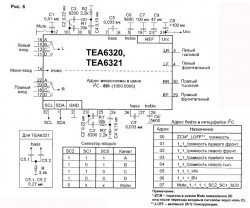
There are no audio effects in these microcircuits. Also in stereo technology, the TDA8425 microcircuit is often used (all microcircuits are manufactured by Philips). This stereo chip has a pair of switchable inputs and several interesting, but essentially useless audio effects. The connection diagram for TEA6320 (TEA6321) is shown in Fig. 6. Since they are designed to control an external processor through the SCL pins. SDA interface 12C (you can read more about this interface in), then no “conveniences” of control are provided.
Several pairs of DACs are simply built into the chips. Each pair of DACs (stereo!) regulates its own parameter (volume, timbre, etc.), the values of which are prepared and sent to the chip by an external processor. There are no functions like “increase the volume by 1 step” - all this rests on the shoulders of the external processor, that is, in this case, it itself must increase the number in the “volume” cell by 1 unit in its memory, and send the result to the audio processor .
From a programmer’s point of view, this is convenient: it is always much easier to write a new program (after all, you still have to create it) than to try to find a more “convenient” audio processor, but, at the same time, a “fat cross” has been put on the non-processor version of the circuit. “Make” the chip work using conventional digital chips and mechanical switches are almost impossible.
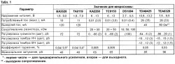
For “serious” and, at the same time, inexpensive devices, the author recommends the TEA6320 or TEA6321 chip. In all respects, they are noticeably ahead of most other microcircuits even in their series, this can be clearly seen from Table 1. The number of adjustment steps (smoothness) they have is one and a half to two times greater than most modern TVs and car radios, and the cost is one of the lowest on the audio processor market.
If in most industrial quad-stereo audio devices it is possible to balance the volume of four speakers only through the “front-rear” (front-rear) and “right-left” (balance) controls, which, to put it mildly, is quite tedious, then with these microcircuits (and only They have the entire TEAbZxx series!) The volume of each of the 4 loudspeakers is adjusted separately.
Additionally, the microcircuits have 4 pairs of independent stereo inputs (usually only 2-3 pairs of inputs are enough) and one mono channel (for the peak signal). TEA6321 has a slightly larger range of bass adjustment, but it also requires a little more external elements. These microcircuits have a gain greater than unity (at maximum volume), i.e. they allow in some cases to do without a preamplifier.
But in general, the TEA6320 (TEA6321) connection circuit does not have any special features (Fig. 6). Elements C2…C4, R1, R2 are pre-amplifier feedback, capacitors C5 and C6 are external elements of the bass and treble tone controls. All adjustments and switching of inputs are made through the serial interface; using the button you can only mute the sound (“Mute” mode).
Despite the presence of 4 outputs, these microcircuits are ordinary stereo processors: the same signals are supplied to the front and rear channels, without any delays or phase inversions. But the ability to adjust the volume in each channel and the low price justify the use of such microcircuits.
The microcircuit is controlled by 8 bytes of data, the command format is as follows: “Start” - microcircuit code (80h) - data byte address - data - “Stop”. The microcircuit operates only in data writing mode, although it “responds” to the read command (FFh are always read). You can transfer any number of bytes of data at one time.
For example, if you need to change the timbre of the bass and treble, we send the commands:
“Start” - 80h - 05h (address of the “LF” byte) - “LF” byte - “HF” byte - “Stop”.
If you need to change non-consecutive bytes, for example, the overall volume and timbre, then we either issue two commands, or in one command we sequentially write all the bytes from volume to timbre into the chip.