Coaxial cable known as a video signal transmission medium. It has the following advantages:
cheapness;
ease of use;
ease of implementation.
The cable is available in a variety of specifications. Type RG599 / U, which is often recommended, also has different parameters. Similar cables of types 6 / U and 11 / U are used. They are included in the group of television cables, where the first two letters RG or RK indicate a waveguide for radio frequencies, and the remaining entries are types.
Coaxial Cable - Device
The coaxial cable contains a shield separated by an insulating layer with a central conductor. The top of the cable is sheathed. Between the central conductor and the screen there is a dielectric layer, from specifications which largely depends on the quality of the transmitted video signals. The video signal is transmitted through the center conductor, which is made of copper or copper-plated steel. The value of its resistance is determined by the material and the size of the section. A core with a steel core significantly increases the resistance of the circuit and cannot be used in television surveillance systems. When choosing a cable, it must be carefully examined. Steel can be seen by its characteristic silver color. The core diameter should be chosen larger, since it has less active resistance. It transmits the signal farther and in better quality. The price of such a cable is higher and it is more rigid. If you need a cable with more flexibility, choose a center wire woven from thinner ones. According to the characteristics, it is slightly inferior to a single-core cable.
The center conductor and the braid are separated by polyethylene insulation. Also used are polyurethane, polyethylene foam or non-combustible polymer material containing fluorine. Foamed dielectric reduces video signal loss, but it absorbs moisture better and is not recommended for use in a humid environment. Hard polyethylene increases the rigidity of the cable, it is more resistant to mechanical stress. It is more difficult to lay it, and the characteristics are somewhat worse. If the dielectric is chemically foamed, its resistance to temperature and humidity, as well as to mechanical damage, decreases. When it is physically foamed, it has the same strength and environmental resistance as rigid polyethylene, and its parameters are much better.
The copper braid shields from obstacles and acts as a second grounding conductor. The denser and thicker it is, the better the shielding quality. Liquid Braid is only suitable where there are few obstructions, under normal conditions of use. It is also suitable for cable laid in metal boxes or pipes. For unknown application conditions, choose the cable with the greatest protection against external influences. If the characteristics cannot be determined, the cable with the highest density braid and the copper conductor of the television signal is selected. A modern television cable contains non-ferrous metal foil along with a braid. The result is a shielding effect of up to 100%, although the cost and weight become higher. If a single foil is used for the screen, the cable is not suitable for tele systems. Polyvinyl chloride (PVC) outer insulation protects the internal components from environmental influences. The difference from a conventional wire with a screen lies in the higher quality of materials and normalized characteristics. Cables should be selected according to their characteristics so that the resolution allows them to be used. For example, RG-59 and PK-75-4 cables can transmit a signal up to 300 m, while RG-11 and PK-75-7 cables can transmit a signal up to 500 m. At the same time, external obstacles are more affected on a long cable, and attenuation also increases signal. As the length increases, the brightness first decreases, then blurry pixels appear, and the image on the screen begins to double. To reduce signal loss, you should take a cable with a larger diameter (it is indicated on the marking, after the number 75).
Coaxial Cable Specifications
The technical characteristics of the cable largely determine how the TV will work.
impedance
The indicator represents the total active and reactive resistance of the central core. It is measured in ohms and the standard value is 75 ohms. The impedance of the cable and the elements connected to it must match. If it differs in any detail during the signal path, it results in the loss of clear images, which begin to double on the screen.
damping
The indicator reflects how much the energy of the transmitted signal is lost in the cable and depends on its frequency characteristics. As the frequency of the signal increases, it weakens to a greater extent.
resistance
Active resistance to the greatest extent characterizes the quality of signal transmission and, unlike impedance, is determined by the length, cable dimensions, material properties and depends on the temperature of the medium. Resistance is measured in ohms per meter or per foot of length. The proprietary cables use high-quality silver-plated television signal center conductors.
capacity
Coaxial cable is a long capacitor. Similarly, its capacitance is measured (pf / m, pf / ft). This parameter is influenced by the design of the cable and the properties of the insulation. Particular attention is paid to it in digital television.
conventions
In general, the cable is shown as PK.Wd-mn-q, where:
RK - radio frequency, coaxial;
W - nominal wave impedance (50, 75, ..., 200 Ohm);
D - outer diameter (usually - 5.6-7.5 mm);
M is a number indicating which insulation group and the degree of heat resistance of the cable;
N is development number;
Q - additional characteristic (C - high uniformity, G - tightness, etc.).
cable splicing
Disassembly of the ends of the center conductor is often done by butt soldering. To do this, the ends are cleaned and soldered together. Thick conductors are cut in half with a needle file and soldered so that there are no protrusions and thickenings. Thin wires are soldered with an overlap. If the central core is multi-wire, it unwinds, each wire is stripped and connected. It is important to restore the insulation of the cable inside so that the characteristic impedance does not change significantly. To do this, a longitudinally cut tube of insulation is put on the central core, the seam of which is welded with a soldering iron. The braid is wrapped with a bandage of tinned wire and soldered at the ends.
Then the braid is closed with insulation from the outside, after which the connection is wrapped with PVC tape for the entire length. When soldering the central cores, they should not be allowed to overheat, which leads to a displacement relative to the axis and a change in the wave resistance. For soldering, soft solder of the POS brand is used with a numerical marking that characterizes the tin content in it (usually 30% and 61%). The power of the soldering iron is 25-100 W at a supply voltage of 220 V. Rosin with alcohol or solder fat is used as a flux.
smart connections
The quality of the connection should be treated with particular care, since just one badly installed connector can lead to image degradation. The main connection methods for connectors are as follows:
soldering (SR-50-74-PV);
crimping;
screwing installation (twist-on).
Soldering is cheaper than crimping the cable. But it requires highly qualified performers. Crimping is reliable, but the main drawback is disposability. Screwing the connectors makes it easy to install, but the method has low reliability.
threaded connector
Processing is simple: a connector of the appropriate diameter is selected and wound onto a cable with a braid bent onto it. In this case, the edges of the insulation and the connector must match. The device is selected for dry heated rooms. When mounting outdoors, the required tightness of the connector is not achieved, and the braid quickly oxidizes. When using a coaxial cable for a video camera, detachable connections are made in the box. Then the device can be easily replaced when it fails. If the F-connector is large in diameter, an electrical tape is wound around the end of the cable in accordance with the diameters. Then an F-connector is screwed onto it so that the cable can be pressed in with a little effort, and the excess part of the braid is cut off.
Coaxial Cable - Crimp Connector Mounting
The cable is crimped using the following tools:
crimper (crimper)
stripper (end stripping device)
cable cutter;
cable refilling device.
The connector is installed on a coaxial cable so that the braid does not wrinkle. When crimping is carried out, no significant force is required. The most difficult installation is to make on a polyethylene sheath, which is difficult to squeeze in due to its high hardness. But it is better able to withstand climatic changes and is more durable. Crimping tool for RG6 cable has 2 sizes:
0.324 "- to standard connectors;
0.360" - reinforced connectors.
When using RG11 cable, crimping is done with a 0.475" tool that fits many connector modifications.
If the crimping dimensions of the tool and the connector are not observed, the installation will be carried out in full or it will be possible to crimp with the destruction of the connector housing. If crimping is done with improvised means (hammer, pliers, etc.), the equipment deteriorates, and the desired connection quality will not be achieved. Special tools are also needed for stripping antenna cable.
Crimping is done as follows:
1. The cable is cut off at the very end and the insulation is stripped. It uses a tool, like a clothespin. It is adjusted so that when cutting, the blade does not touch the center conductor. Many strippers are capable of stripping cable with multilayer shields without damaging them.
2. A contact is attached to the central core to squeeze it in and fix the connector. No special qualifications are required here. It is important to position it correctly in the tool so that the working part is not damaged when the crimp is made. Installation is carried out in one movement.
In order for the crimping to be carried out qualitatively, a crimping tool from the manufacturer of the coaxial cable is used. Compression connectors are the most perfect. The connector is made of nickel-plated brass. Distinctive feature A crimp connector is the presence of a plastic sleeve inserted between the deformed metal part of the connector and the cable. The connector is mounted by pressing the sleeve and provides complete sealing and fixation of the cable.
The most reliable ways to mount connectors on a coaxial cable are crimp and compression. Despite the fact that the methods are disposable, they are of high quality and durability of the connections. During installation, it is important to use the necessary crimping tools to prevent damage to the connectors and create strong connections.
In order to connect a television cable, connect several wires into one or divide the antenna cable into several, special plugs, connectors and splitters are used. How to crimp a coaxial cable, see our video. The cases when it is necessary to connect a connector or an adapter with an antenna cable may be different: - Connecting television and satellite devices. - Separation of the cable for several TVs. - Laying a new or repairing an old cable in case of a break. - Changing the length of the cable when transferring equipment, etc. From the tools you will need: a knife, wire cutters and pliers. For connection, F-connectors of various types are usually used. It is necessary to follow a certain procedure for stripping the wire and connecting it to the coupling. Knowledge of the device of a coaxial cable will greatly facilitate the matter: - The central element is a conductor in the form of a copper core, through which the television signal arrives. - An insulating sheath follows the top of the signal wire. - The next element is aluminum foil, which acts as a second conductor, and (or) a braid of tinned copper wires. This braid acts as a protective shield, preventing interference from external electromagnetic waves. - Covers still another layer of plastic insulation, which also performs the function of protection against mechanical influences. To connect the antenna cable to the plug, we first need to prepare the cable: - We retreat from the edge of the cable one and a half centimeters and make a thin circular cut. Try to cut the outer layer of insulation carefully and not damage the thin hairs of the screen under it. - Remove the cut piece of insulator. Gently and evenly peel back the screen hairs and foil strips. - Stepping back from the folded edge of the foil 2 mm, make another circular cut of the inner insulator. - Take the connector and turn it clockwise onto the prepared end of the cable until it stops. We take pliers or pliers to help and twist until we see an insulator near the beginning of the nut. - Bite off the excess part of the center conductor with wire cutters, leaving 1-2 mm from the edge of the connector. Be careful not to damage the signal wire, shielding braid. Do not forget that the antenna coaxial cable should not have sharp bends during installation. If you need to run the cable in a 90 degree angle, be sure to use the right angle adapters. Also, when wiring a cable to several TVs, you will need splitters (splitters) and connecting adapters. This will help to avoid TV interference and signal loss.
Coaxial cable is the most common in the practice of video transmission. The frequency dependence of the attenuation characteristic on length limits the application distance to the resolution requirements of the system. For systems with high resolution (more than 400 TVL), the following restrictions must be observed: for RG-59 or RK-75-4 cables, the maximum video transmission distance is up to 300m; for RG-11 or RK-75-7 cables, the maximum video transmission distance is up to 500m. With a large spatial separation of the source and receiver of signals, special measures for galvanic isolation are required. With an increase in the length of the coaxial cable, the degree of influence of external interference on it increases, the attenuation of the signal increases when it passes through the cable. When a certain cable length is exceeded, the losses in it lead first to a decrease in brightness, and then to blurring of pixels and the appearance of a characteristic dark plume from dark elements of the image. The amount of attenuation depends on the quality of the materials used to make the cable. The specific attenuation in a RK type coaxial cable can be judged by its design: the larger the diameter of the internal insulation of the cables (in the designation of the cable brand, it is indicated in millimeters after the number 75), the lower its specific attenuation.
The structure of the coaxial cable
A coaxial cable consists of a center conductor, an inner dielectric, a shield, and an outer sheath.
The center conductor of the cable is designed to transmit a signal from one point to another. It is made from materials that conduct well electricity. Usually copper is used, which is suitable for these purposes in terms of its electrical, mechanical and cost parameters. Other materials may also be used for some special purposes. These include aluminum, silver and gold. The central conductor can be either single-core or stranded.

Rice. 1. Coaxial cable with central solid conductor and double shield
![]()
Rice. 2. Coaxial cable with a central stranded conductor and a braided shield
Single-core is a central conductor made in the form of one straight wire (Fig. 1). A solid conductor is well formed, but does not have good flexibility. Therefore, solid conductor cables are usually used in fixed installations.
Stranded stranded - is a conductor consisting of many thin wires twisted together (Fig. 2). These cables are flexible, lighter and are mainly used in mobile installations. However, in terms of its characteristics, such a cable is somewhat inferior to a cable with a single-core conductor of the same size.
The internal dielectric, also called the cable's internal insulation, plays an important role in coaxial cables. First of all, it is a material that isolates the center conductor from the screen. But it also determines the impedance and capacitance of the cable.
Typically, polyethylene is used in general purpose cables, and fluorine-containing polymers are used in the production of non-flammable cables.
Cheap cables have a rigid polyethylene dielectric. A more serious manufacturer uses foamed polyethylene, which provides a lower linear attenuation of the signal in the cable at high frequencies.
It is worth noting that some manufacturers foam the dielectric chemically. The result is a low-density polyethylene compound that is susceptible to mechanical damage and unstable to impact. environment in the form of temperature and humidity.
The highest quality cable is obtained with a physically foamed dielectric. It contains up to 60% air bubbles, which reduces the attenuation of high frequencies of the signal. In terms of strength, physically foamed polyethylene does not differ from conventional solid non-foamed polyethylene, providing the necessary flexibility and resistance to mechanical stress. And, finally, having high resistance to temperature fluctuations and humidity, the physically foamed dielectric will ensure the stability of the parameters and long-term operation of the cable.
The screen plays two important roles. It acts as a second conductor connected to the equipment's common ground wire. At the same time, it shields the signal conductor from extraneous radiation. There are different shielding methods for cables with different tasks. These are foil screen, braided screen and combinations of foil and braid.
Braid - a screen that is made of many thin conductors woven in the form of a grid covering a central conductor with an internal dielectric (see Fig. 2). The braid usually has less resistance than the foil, and has better resistance to extraneous electromagnetic fields and electromagnetic pickups. Leads have a different nature and origin. It can be both low-frequency pickups (for example, from industrial network power), and high-frequency (high-frequency noise from the operation of electronic devices and sparking of electrical machines).
The braid can be combined with other types of screens, such as aluminum or copper foil, which give highest value shielding efficiency, since foil allows for up to 100% shielding in combination with a braid (see Fig. 1). Considering that a braid can provide shielding efficiency up to 90%, to achieve 100%, two braids are needed, which significantly increases the cost of the cable, its weight and degrades flexibility. It is much easier to achieve 100% shielding efficiency with a combination of braid and foil. The shielding efficiency of a coaxial cable can be judged by its design: the higher the density of the outer conductor (screen), the more value this setting.
The outer sheath provides the necessary protection for the internal components of the cable. The sheath protects the cable from climatic, chemical exposure and protect from sunlight. According to the type of sheath, cables can be divided into standard and special versions.
Standard cable - has a conventional, most often PVC sheath, which protects the cable (including stranded) from mechanical stress and moisture, and also plays the role of electrical insulation.
Basic parameters of coaxial cable
Impedance- the main indicator that determines the possibility of transmitting signal energy over the cable between the source and the receiver. All elements in the signal path, connectors and the cable itself must have the same impedance. Failure to do so results in internal reflections in the cable, which can result in double contours in the image. most common cause reflections are poor-quality connectors or their incorrect installation, as well as the use of connectors and cables of different impedance.
The standard video cable impedance is 75 ohms.
attenuation- indicator of signal energy loss inside the cable. Each cable has its own frequency properties, so the attenuation at different frequencies is also different, and the higher the frequency, the greater the attenuation.
Resistance- an indicator of the quality of the conductor, literally showing what part of the signal energy will turn into heat. The result of such losses is a decrease in the signal level, and, accordingly, the dynamic brightness of the image.
Resistance is measured in ohms (Ω), and is otherwise referred to as DC resistance or active resistance. For cables, the resistance is specified as ohms per 100 meters (Ω/100m) or ohms per 1000 feet (Ω/1,000 feet) and may also be referred to as linear resistance.
The resistance depends on the material of the conductor, its size and temperature.
The best cables have chemically pure copper signal conductors or are plated with a thin layer of silver.
Capacity. By design, any coaxial cable is an elongated capacitor. Capacitance is measured in farads (F) and cable capacitance is measured in picofarads per meter (pF/m) or picofarads per foot (pF/ft).
Cable capacitance affects the high-frequency components of the video signal, that is, the clarity and detail of the image. The capacitance is determined by the quality of the dielectric and the design of the cable. This parameter is especially important when transmitting digital signals.
Coaxial cables of all types used for video surveillance systems (drop cables, trunk cable, distribution cable, subscriber cable) must have a characteristic impedance of 75 ohms.
Symbols of domestic coaxial cables according to GOST 11326.0.78 are as follows: PK.W-d-mn-q.
The first two letters (RK) indicate the type of cable - radio frequency, coaxial.
The first number W means the value of the nominal wave resistance (50, 75, 100, 150, 200 Ohm).
The second number d corresponds to the nominal diameter of the insulation rounded to the nearest whole number for diameters greater than 2 mm (except for the 2.95 mm diameter which is rounded to 3 mm and the 3.7 mm diameter which is not rounded).
Depending on the diameter of the cable insulation, they are divided into subminiature (up to 1 mm), miniature (1.5-2.95 mm), medium-sized (3.7-11.5 mm) and large-sized (more than 11.5 mm). The nominal diameter for the insulation of the coaxial cable must be equal to one of the values of the following series:
0.15; 0.3; 0.6; 0.87; 1; 1.5; 2.2; 2.95; 3.7; 4.6; 4.8; 5.6; 7.25; 9; 11.5; 13; 17.3; 24; 33; 44; 60; 75 mm.
For connections between equipment, cables from 5.6 to 7.5 mm are mainly used, for trunk connections, cables of 9-13 mm are used. Usually the best is 11.5 mm.
The number "m" indicates the insulation group and the heat resistance category of the cable:
1-cables with solid insulation of normal heat resistance;
2 cables with solid insulation of increased heat resistance;
3-cables with semi-air insulation of normal heat resistance;
4-cables with semi-air insulation of increased heat resistance;
5-cables with air insulation of normal heat resistance;
6-cables with air insulation of increased heat resistance;
7-cables of high heat resistance.
The number "n" indicates the serial number of the development.
In some cases, in symbol an additional letter (q) is introduced:
C - cable of increased uniformity and phase stability;
G - sealed;
B - has an armored cover;
OP - has a fly-out of galvanized steel wires over the shell.
For example: RK-75-4-11-C - this means radio frequency, coaxial with a nominal wave impedance of 75 ohms, a nominal insulation diameter of 4.6 mm, with continuous insulation of normal heat resistance, development serial number 1, cable of increased uniformity.
Marking and designation of imported cables is established by international, national standards, as well as by manufacturers' own standards (the most common series of brands are RG, DG, etc.)
When installing coaxial cables, it is necessary to observe the minimum bending radii (specified in the standard or specifications for cables of different brands).
So, for cable RK-75-4-11 the minimum bending radius at t> +5°C is 40 mm, and at t< +5°C - 70 мм.
It is not recommended to bend the cable under a smaller radius. It should also be taken into account that the cable is pulled out by its own weight.
This must be taken into account when laying the cable (vertically) and between buildings. It should be fixed to the wall (mast) or auxiliary cable every 1-2 m.
When storing cables with air and semi-air insulation, their ends must be protected from moisture penetration into the cable, and during operation, sealed connectors must be used.
You can splice two pieces of coaxial cable 1 in the way shown in rice. 3 for which the parts of the central conductors of the cables freed from insulation must be shortened as much as possible. The soldering points of the conductors should not have significant thickenings, therefore, the central (internal) conductors are partially cut with a file (one side of the conductor will be flat). After tinning with tin-lead solder, the sawn ends of the conductors are laid on top of each other and sealed. In order not to change the wave impedance, it is necessary to restore the internal insulation in place of the spliced section of the cable 3 (previously made from the internal polyethylene insulation removed from the cable). Detail 2 cut out of tin or copper foil with a thickness of about 0.1 ... 0.2 mm and installed over the connected section with restored insulation 3. Soldering the cable braid should be carried out at the cutouts of the part. 2. To give strength to the connection, the part 2 along the entire length, it is advisable to wrap tightly with electrical tape 4.
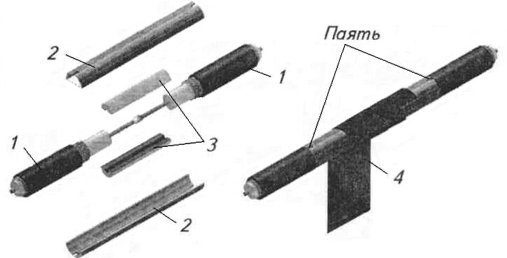
Fig.3. Method for splicing coax cables.
The manual for RD 78.145-93 indicates the following method for splicing a coaxial cable:
Remove the upper polyethylene sheath from the ends of the cable intended for connection at a length of at least 30 mm from the ends;
dissolve the metal braid, consisting of thin copper wires at one end of the cable by 20 mm, cut it to the same length at the other end and twist 4 bundles from the loose copper wires of the braid and tin them;
- tin the braid of the second end of the cable around the circumference for a length of at least 5 mm (in order to avoid melting the polyethylene insulation of the central core, it is necessary to put protective insulation of cable paper in 2 layers under the braid);
- release the central core of the cable from insulation for a length of at least 15 mm;
- twist the central cores of the two cables together and solder.
The length of the bare layer should be 15 mm;
- cut the removed insulation of the central core, put it on the junction of the central cores and, straightening with a soldering iron, close the junction;
- solder four tinned bundles to the tinned braid of the second cable symmetrically from all sides;
- put on the finished connection of two cables the removed outer insulation cut along and melt it with a soldering iron with the main cable insulation.
When soldering the central core, it should not be allowed to overheat, because in this case, a displacement occurs and the uniformity of the wave resistance is disturbed.
When installing cables and cutting braids, the latter cannot be cut: the braid must be untwisted, twisted into one or two pigtails and tinned.
When cutting the cable, it is necessary to ensure that the central core is not accidentally cut off and that the wire braid is not closed to it.
With such termination of the cable, its uniformity is practically not disturbed. Otherwise, repetitions, vertical stripes may appear on the screen of the video monitoring device, and the noise immunity of the cable may deteriorate.
If the coaxial cable is laid parallel to the mains, problems arise. The magnitude of the EMF induced in the central core depends, firstly, on the current flowing through network cable, which, in turn, depends on the current consumption of the load on this line. Secondly, it depends on how far the coaxial cable runs from the power cable. And finally, it depends on how long these cables run together. Sometimes proximity within 100 m has no effect, but if power cable large current flows, even 50 m may affect the quality of the video signal. When installing, try (whenever possible) to make sure that the power and coaxial cables do not run very close to each other. For a noticeable reduction in electromagnetic interference, it is necessary that the distance between them is at least 30 cm.
On the screen of a video monitor, electrical interferences look like several thick horizontal stripes slowly sliding up or down. The speed of their movement is determined by the difference between the frequency of the video signal fields and the industrial frequency, and can be from 0 to 1 Hz. As a result, stationary or very slowly moving stripes appear on the screen. Other frequencies appear as different noise patterns, depending on the interference source. The general rule is that the higher the frequency of the induced unwanted signal, the finer the details of the noise pattern. Intermittent pickups, like lightning or a passing car, will give an irregular noise pattern.
Breaking the cable in the middle and terminating the resulting ends will result in some loss of signal, especially if the ends are badly terminated or poor quality BNC connectors are used. A good termination gives a signal loss of no more than 0.3:0.5 dB. If there are not too many of these splices in the cable, then the signal loss is negligible.
1. Choice of connector.
The next step is high-quality connection coaxial cable to the equipment. Quite often, a single poor-quality connector leads to a loss in image quality of the entire system. Poor crimping or soldering often results in cable reflections, loss, and distortion.
The selected cable must be designed for cutting the desired connector into it, or the appropriate adapters must be provided in the specification. Leading cable manufacturers also produce cable connectors, or indicate in the specifications the recommended type of connector from another manufacturer, which ensures high-quality cutting of the connector onto the cable.
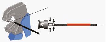
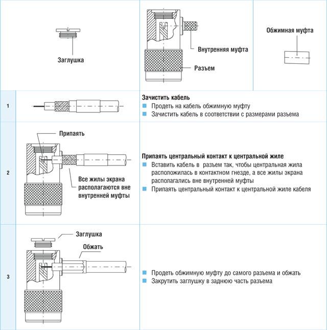
Clamp connections are used to connect the coaxial cable to the equipment. This connection for receiving television antennas, outdoor video cameras, etc. is shown in fig. 1.
![]()
Before connecting the coaxial cable to the equipment, the cable must be cut, the connection points must be tinned, i.e. center wire and outer braided shield. The shielding braid when cutting the cable is wrapped in two layers. The connection point of the cable with the connector must be sealed. If this is an antenna, then it is necessary to seal the antenna box so that precipitation does not get in and oxidation does not occur at the connection point.
The coaxial cable from the connection point to the nearest connection must be intact, without breaks, because at the junction of the two segments, the uniformity of the wave resistance is disturbed, which leads to the appearance of a reflected signal, loss of the transmitted signal level and image repetitions.
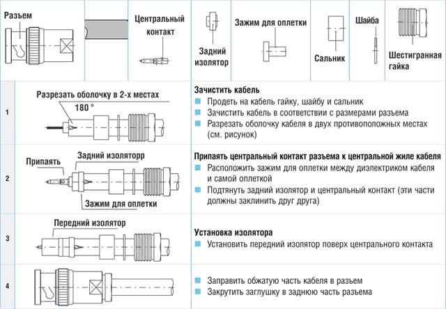
To connect equipment between elements of a video security system, cable television systems, etc., use detachable connections such as BNC, F, CP-75-154 P (plug), SR-75-155 P (socket), SR-75-167 PV (plug), SR-75-158 PV (socket), SR-75-201 FV (plug), SR-75-202 FV (socket). Each type of cable has its own connectors (this is determined by the diameter of the cable).
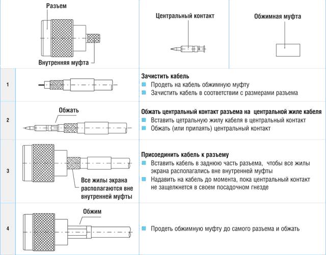
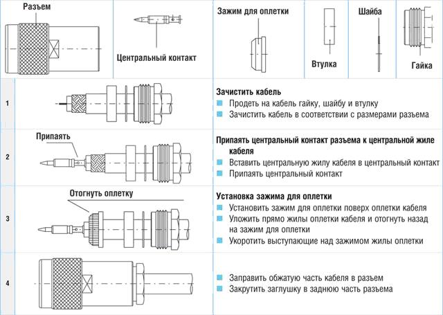
Cable termination for type F connector is shown in fig. 2.

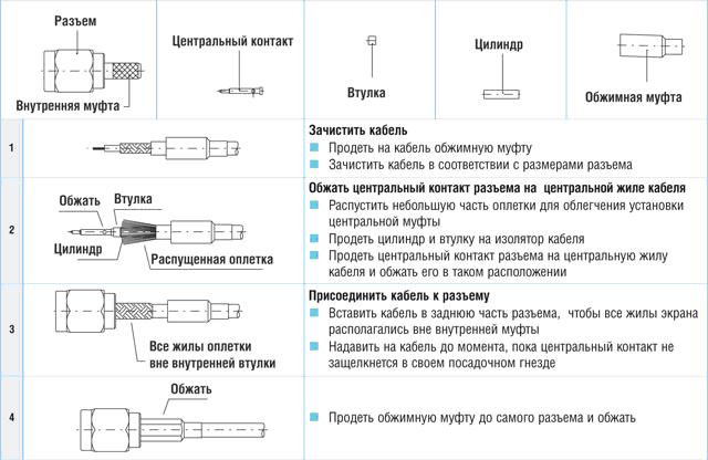
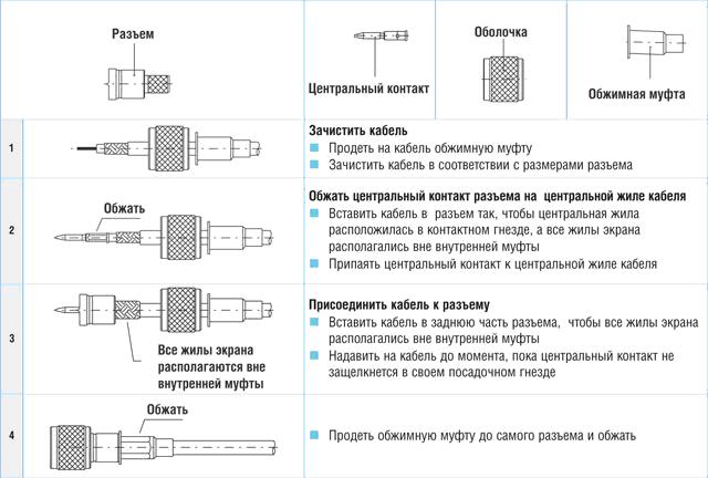
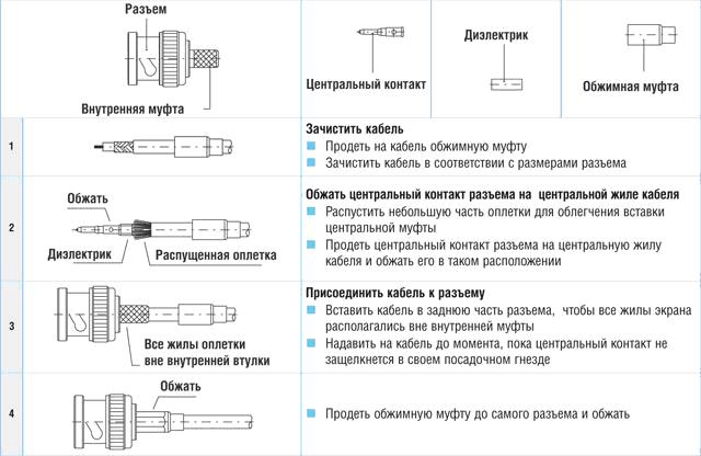
Mounting Crimp BNC Connectors
Rice. 3. Stripped coaxial cable

Rice. 5.
Rice. 5.
- the end of the cable is cleaned with a special tool (Fig. 3);
- a plastic cap or a heat-shrinkable tube and a crimp ring are put on the cable (Fig. 4);
- the central contact of the connector is put on the central conductor of the cable (Fig. 4);
- the central contact is crimped on the central conductor of the cable with crimping pliers;
- after the preliminary fluffing of the braid, the cable is inserted with force into the connector until the central contact is fixed in it, after which a crimp ring is put on the connector shank until it stops. In this case, it is necessary to press the cable sheath to the shank (Fig. 5);
- crimping pliers are used to crimp the ring, a plastic cap or a heat-shrinkable tube is put on the connector shank, which is wrapped with a building hair dryer (Fig. 6).
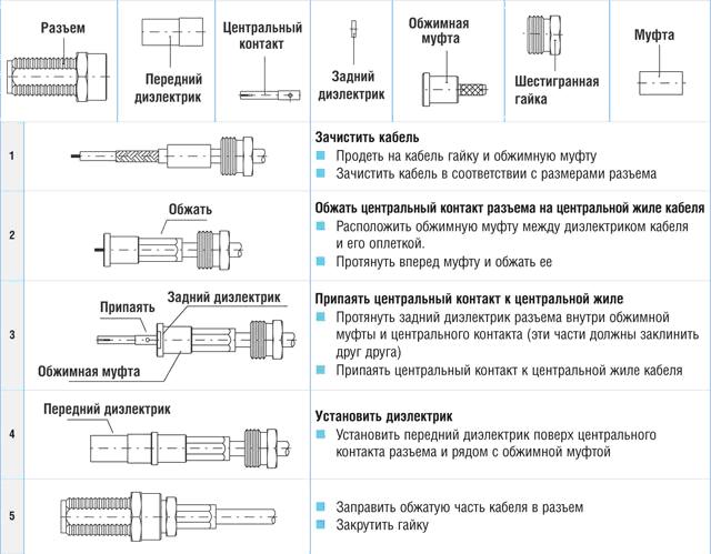
Mounting compression BNC connectors
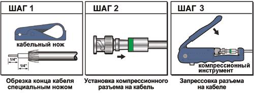
Rice. 7. Technology of cutting a compression connector into a cable
Installation is carried out in three steps, as shown in Fig. 7.
For high-quality cutting of connectors into a cable, it is better to use branded cutting and crimping tools recommended for this type of cable and connectors, otherwise it is problematic to guarantee the quality of contact.
2. Tinning and soldering of the cable.
Soft solder is used for tinning and soldering. The radio master needs to be able to solder with soft solder. Fast solder is usually a tin-lead alloy with a tin content of 30 to 60%. The content of tin in the solder can be determined by the crunch that the fast ice makes when it is bent. The crunch is stronger, the higher the percentage of tin.
In accordance with the standard, tin-lead solders are marked with the letters POS and a number indicating the percentage of tin. With an increase in the amount of tin from 18% to 64%, the melting point of the solder decreases from 240 0 to 180 0 C. Since tin is a scarce material, it is recommended to use alloys with a moderate tin content (most often POS-30).
For the production of tinning and soldering, electric soldering irons with a power of 25 W to 100 W are used. Supply voltage of electric soldering irons 220 W alternating current or for rooms with increased danger, or in especially dangerous rooms for safety reasons, electric soldering irons with a supply voltage of 36-42 V AC are used.
The tip of the electric soldering iron must be constantly kept clean and at regular intervals cleaned of scale.
When soldering with soft solder, the soldering points must be carefully cleaned with a fine file, knife or sandpaper. To reduce the oxidation of the stripped surface of the conductor, an alcohol-rosin mixture or rosin is used for better surface tinning, i.e. fluxes. They are applied to the surface along with solder. Before soldering wires or elements, both surfaces must be tinned and then soldered. It is necessary to warm up the solder until complete melting and the formation of a drop. Then bring the drop to the place of soldering and heat until the two surfaces are completely melted. In this case, it must be taken into account that overheating can melt the insulating material between the center wire and the shielding braid in the cable. Soldering one point should be no more than 2 seconds.
When using an electric soldering iron, it is necessary to check that the power wire is intact and that there is no melted insulation. It is unacceptable that one of the power wires through the heating coil touches the body of the soldering iron. The soldering iron handle must be intact. When soldering, do not allow the power cord to touch the heated parts of the soldering iron in order to avoid melting the insulation. When soldering elements that do not allow static interference, it is necessary to solder on grounded tables and have a shielding bracelet.
It is not allowed to work with a soldering iron that has one of these defects!
Crimp (1) A
Crimp (2) B
Crimp (3) C
![]()
Crimp (4) D
Crimp (5) E
Crimp (6) F
Crimp (7) G
Angled connector (1) H
Connection (clamp) connector (1) I
Connection (clamp) (2) J
Connection (clamp) (3) K
Connection (clamp) (4) L

Screw on (1) M

Semi-rigid type (solder) (2) N

Instruction
If cable need to be increased, purchase an additional piece of it of the required length. Its characteristic impedance should be the same as that of the existing cord. If this parameter of the existing cable is unknown, you should be guided by the rule: TV antennas are connected with a cord with a characteristic impedance of 75 ohms, antennas of CBS radio stations with a cable with a characteristic impedance of 50 ohms. The same characteristic impedance has cables for computer networks of an outdated standard ( Today such networks have practically gone out of use). The thickness of the cable is chosen depending on its purpose. It is necessary to use a thick cord in two cases: its long length (to reduce attenuation) and a significant power of the transmitted signal. If at least one of these conditions is met, cable must be large in diameter.
Before carrying out any work on cables, be sure to unplug all equipment connected to them. In many appliances there are capacitors connecting the common wire to one of the network wires. In this case, if you grab the braids or the central cores of two cables or the two ends of one cut cable at the same time, you can get a painful electric shock. using an AC voltmeter. If cable leads to a transmitting device (for example, radio stations CB standard), you should additionally make sure that there is no high-frequency voltage on it using a wavemeter. Even at low power, exposure to such a voltage on the skin can cause burns.
Splicing cables by twisting or soldering is possible only if the equipment connected to them is not transmitting, since with such a connection the standing wave coefficient deteriorates noticeably, which threatens the transmitting equipment with failure. First, strip both cables. Make a longitudinal cut on the outer insulation, unwind the braid, then twist it aside. Then, use wire cutters to remove the insulation from the central core. Connect the braid of one cord to the braid of the other, do the same with the central cores. Never allow a short circuit between the braid and the center conductor. If applied soldering, do it quickly so as not to melt the insulation of the central core, which also threatens to short circuit. Carefully insulate all connections.
To a much lesser extent, the standing wave ratio changes when connecting coaxial cables using connectors. They there are two types: F (television) and BNC. Only the latter are suitable for transmitting equipment. They, in turn, must such the same wave resistance as cable, and therefore are available in two versions: CP50 and CP75. To connect the cable using connectors, purchase a plug and socket of the same standard. It is better if they are designed for connection without the use of soldering, so as not to arose the risk of a short circuit from melting the insulation of the central core. Attaching a plug to one end of the cord and a socket to the other, connect them to each other. If the connectors have bare contacts (usually sockets are produced in this design), insulate them.
If the equipment used in conjunction with the cable is transmitting, be sure to check with a meter coefficient standing wave, whether this parameter has gone beyond the permissible limits. After that, start using the equipment.
Satellite television, unlike conventional terrestrial television, makes it possible to view digital channels in HD quality on new LCD and LED TVs. Thus, the colors on the screen look realistic, and the picture allows you to create a "presence effect". In order to be able to cover the entire range of TV channels from all satellites available in orbit, you can either use a motor suspension for a satellite dish, or connect two or more "dishes" to one receiver at the same time.
You will need
- - DiSEqC.
Instruction
Fold very thin core wires between with an overlap so that they overlap each other by about 10-15 mm. Cover the place of soldering with a flux prepared from rosin dissolved in alcohol. Soldering thin wires is more convenient lead not with a soldering iron, but put a place connections for a few seconds in a bath of molten solder.
Paving the coaxial cable between separate buildings, try to place it vertically where possible. Fasten cable directly to wall, to an additional mast or auxiliary cable. The distance between fasteners is not must exceed 2 m.
At long-term storage cable, protect its ends from moisture ingress. To do this, use universal sealed connectors, which can later also be used during cable operation.
Related videos
Capacitors can be connected in series and in parallel. The resulting capacity in both cases is calculated by the formulas. Such a connection is used in cases where there are no capacitors with the required parameters, but there are others.
You will need
- - soldering iron;
- - wires;
- - wire cutters;
- - calculator.
Instruction
Any capacitors can only be connected when they are discharged and disconnected from the rest of the circuit elements. Do not short-circuit them - use a suitable load. Connect it with insulated wires, without touching live parts. After discharging the capacitor, check with a voltmeter that it is really discharged, also using probes with insulated wires and handles and without touching live parts.
Before carrying out calculations, the capacitance of capacitors should be converted to the same units. In this case, it is irrational to use the SI system, since the unit included in it - the farad - is very large. Depending on which capacitors you connect, you can use picofarads, nanofarads, or microfarads.
By connecting capacitors in parallel, calculate the resulting capacitance by simply summing the capacitances of all capacitors. The operating voltage of this design will be equal to the smallest of the operating voltages of the capacitors included in it.
When capacitors are connected in series, first find the reciprocal of the capacitance of each of them, then add these values, and then find the reciprocal of the sum. The reciprocal is the result of dividing one by a number. This one looks like this: Cresult=1/(1/C1+1/C2+ ... +1/Cn), where Cresult is the resulting capacitance, and C1...Cn are the capacitances of the capacitors in the series circuit. With the operating voltage of this design is more difficult. In theory, when capacitors of the same capacitance are connected in series, it is enough to add their operating voltages, and if their capacitances are different, then the voltages will be distributed to them in inverse proportion to the capacitances. In practice, parameter spread and leakage can lead to unpredictable voltage distribution. Therefore, it is most reliable to follow the same rule as for parallel connection: the operating voltage of the entire structure is equal to the operating voltage of the capacitor with the smallest one.
For mixed (series-parallel) connection of capacitors, divide the design into groups of capacitors connected only in series or only in parallel. Calculate the parameters of each of the groups, and then consider it as one capacitor with the appropriate parameters. After that, look at how these groups are connected - in series or in parallel - and calculate the parameters of the entire structure using the appropriate formula. Connect polar capacitors in the same polarity, and in the same polarity, include the design in the circuit where it will work. It is not recommended to connect in anti-series two polar capacitors even of the same capacity to obtain a non-polar one - the spread of parameters and leakage can lead to their failure. At least one polar capacitor makes the entire structure polar.
Coaxial acoustics is most often used in cars. It is a system that is divided into three bands of high, medium and low frequency. Additional speakers, if necessary, are placed on the same axis as the main speaker, which, as a rule, operates at low or medium audio frequencies.

Principle of operation
Coaxial acoustics is implemented through a capacitor, which acts as a frequency filter that separates the sound into high and low frequency ranges. Using a capacitor instead of other filters allows you to achieve a lower cost for such devices, while maintaining decent sound quality. As a rule, coaxial acoustics are two-frequency, but sometimes three-frequency devices are used in the presence of a speaker that reproduces sound at an average frequency.
Pros of coaxial speakers
When installing an inexpensive audio system for auto it is better to install exactly coaxial acoustics, because in quality it does not lose to similar standard component systems, but coaxial speakers are much lower in cost. Also, the sound quality of music can be determined by the location of the coaxial speakers and the location of the sound source in the vehicle. In combination with component acoustics, coaxial speakers are also installed to provide sound to rear seat passengers.
Such speakers are installed in the doors and on the rear shelf of the trunk of a car.
The advantage of coaxial acoustics also is its ease of installation. Component systems require a number of rules to be followed during installation, since each of the sound sources is autonomous and must be placed in accordance with special rules and using acoustic zones. Most often, the manufacture of special shelves is required. for speakers and the creation of additional sound insulation, as well as the purchase additional equipment to amplify the sound. Coaxial speakers do not require an amplified radio, the cost of which can also be quite high. Connecting a strong component audio system to a weak radio will be useless and will not give the desired improvement in sound quality.
Coaxial acoustics is often used in small cars.
Cons of coaxial systems
Among the disadvantages of coaxial systems is their relatively poor sound quality compared to full-fledged component systems. This is due to the fact that sound of different frequencies comes from the same speaker - in the process of sounding, the frequencies are mixed, which has a negative effect on the sound. Such distortion is not observed in the component system, since it uses several speakers of different frequencies, which are connected to different channels of the amplifier or radio.
Antenna cable designed to connect an outdoor antenna to an indoor access point. Antenna cable improves the quality of the received signal. To connect the antenna cable, it is recommended to use a special adapter.

Instruction
For mounting connector no soldering equipment required. Remove the top insulation for a length of about 20 mm. Trim the top layer of insulation around the circumference. Be careful not to damage the metal braid. Wrap the braid on the outside cable like a stocking.
Remove the inner core insulation. Screw the sleeve onto the wrapped braid using pliers. The coaxial connector is ready. screw it on antenna plug. For connections to the antenna several receivers, connect the plug to the splitter and antenna amplifier.
The extension of the antenna cable in order to lengthen it is carried out precisely through the connector device, ordinary twist or


