- twisted pair
- optical fiber
Coaxial cable(from Latin co - together and axis - axis, that is, “coaxial”), also known as coaxial (from the English coaxial), is an electrical cable consisting of a coaxially located central conductor and screen. Typically used to transmit high frequency signals. Invented and patented in 1880 by British physicist Oliver Heaviside.
The coaxial cable (see figure) consists of:
- (A) - shells (serves for insulation and protection from external influences) made of light-stabilized (that is, resistant to ultraviolet radiation from the sun) polyethylene, polyvinyl chloride, fluoroplastic tape or other insulating material;
- (B) - an external conductor (screen) in the form of a braid, foil, film coated with a layer of aluminum and their combinations, as well as a corrugated tube, a layer of metal tapes, etc. made of copper, copper or aluminum alloy;
- (C) - insulation made in the form of solid (polyethylene, foamed polyethylene, solid fluoroplastic, fluoroplastic tape, etc.) or semi-air (cordel-tubular layer, washers, etc.) dielectric filling, ensuring constancy of the relative position (alignment) internal and external conductors;
- (D) - internal conductor in the form of a single straight (as in the figure) or twisted into a spiral wire, stranded wire, tube made of copper, copper alloy, aluminum alloy, copper-plated steel, copper-plated aluminum, silver-plated copper, etc.
Due to the coincidence of the axes of both conductors in an ideal coaxial cable, both components of the electromagnetic field are completely concentrated in the space between the conductors (in dielectric insulation) and do not extend beyond the cable, which eliminates the loss of electromagnetic energy through radiation and protects the cable from external electromagnetic interference. In real cables, limited radiation output and sensitivity to interference are caused by geometry deviations from ideality.
twisted pair(English twisted pair) - a type of communication cable, represents one or more pairs of insulated conductors, twisted together (with a small number of turns per unit length), covered with a plastic sheath.
Twisting of conductors is carried out in order to increase the degree of connection between the conductors of one pair (electromagnetic interference equally affects both wires of the pair) and subsequent reduction of electromagnetic interference from external sources, as well as mutual interference when transmitting differential signals. To reduce the coupling of individual cable pairs (periodic bringing together of conductors of different pairs) in UTP cables of category 5 and higher, the wires of the pairs are twisted with different pitches. Twisted pair is one of the components of modern structured cabling systems. Used in telecommunications and computer networks as a physical signal transmission medium in many technologies such as Ethernet, Arcnet and Token ring. Currently, due to its low cost and ease of installation, it is the most common solution for building wired (cable) local networks.
The cable connects to network devices using an 8P8C connector (mistakenly called RJ45).

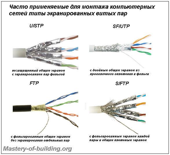
Depending on the presence of protection - an electrically grounded copper braid or aluminum foil around twisted pairs, the types of this technology are determined:
- unshielded twisted pair (UTP - Unshielded twisted pair) - without a protective screen;
- foil twisted pair (FTP - Foiled twisted pair, also known as F/UTP) - there is one common external shield in the form of foil;
- shielded twisted pair (English STP - Shielded twisted pair) - there is protection in the form of a screen for each pair and a common external screen in the form of a mesh;
foil shielded twisted pair (English S/FTP - Screened Foiled twisted pair) - an external screen made of copper braid and each pair in a foil braid;
unprotected shielded twisted pair (SF/UTP - or from English Screened Foiled Unshielded twisted pair). The difference from other types of twisted pairs is the presence of a double external shield made of copper braiding and foil.
Shielding provides better protection from electromagnetic interference, both external and internal, etc. The screen along its entire length is connected to a non-insulated drain wire, which unites the screen in case of division into sections due to excessive bending or stretching of the cable.
Depending on the structure of the conductors, the cable is used single-core or multi-core. In the first case, each wire consists of one copper core and is called a monolith core, and in the second case, each wire consists of several and is called a bundle core.
A single-core cable does not require direct contact with connected peripherals. That is, as a rule, it is used for installation in boxes, walls, etc., followed by termination with sockets. This is due to the fact that copper strands are quite thick and with frequent bending they quickly break. However, such conductors are ideally suited for “cutting” into the connectors of socket panels.
In turn, a multi-core cable does not tolerate “cutting” into the connectors of socket panels (thin wires are cut), but behaves well when bent and twisted. In addition, stranded wire has greater signal attenuation. Therefore, multi-core cable is used mainly for the manufacture of patchcords connecting peripherals to sockets.
Optical fiber- a thread made of an optically transparent material (glass, plastic), used to transfer light within itself through total internal reflection.
Fiber optics is a branch of applied science and mechanical engineering that describes such fibers. Optical fiber cables are used in fiber optic communications, which allow information to be transmitted over long distances at higher data rates than electronic communications. In some cases, they are also used to create sensors.
Currently, this is the most common network conductor. In structure, it has 8 copper conductors intertwined with each other, and good dense polyvinyl chloride (PVC) insulation. Provides high connection speed - up to 100 megabits/s (About 10-12 Mbps) or up to 200 Mbits in full-duplex mode. When using gigabit equipment, speeds of up to 1000 Mbit are achievable.
There is unshielded (UTP) and shielded (STP) twisted pair; in addition to the usual insulation, the second type of twisted pair has a protective shield, whose structure and properties resemble foil. When properly grounded, shielded twisted pair cable provides excellent protection against electromagnetic interference, and even when running STP near a power distribution panel and high voltage lines, stable network operation was observed at speeds in excess of 90 Mbps. If the STP cable is not grounded, then the screen, on the contrary, protrudes, enhances the effect of interference, acting as an antenna.
The cable is easily repaired and extended. Despite the fact that, according to standards, the damaged section cannot be restored, even with numerous sections of repaired breaks, the twisted pair network operates stably, although the communication speed drops somewhat. In addition, in networks based on twisted pair, you can use various non-standard conductors, allowing you to obtain new characteristics and properties of the network.

Regular twisted pair cable is not designed for outdoor wiring. Temperature changes, exposure to moisture and other natural factors can lead to the gradual destruction of insulation and a decrease in its functional qualities, which will ultimately lead to the failure of a network segment. On average, a network cable can withstand outdoors for 3 to 8 years, and the network speed will begin to drop long before the cable completely fails. For outdoor use, you must use a special twisted pair cable for exposed wiring.
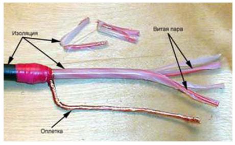
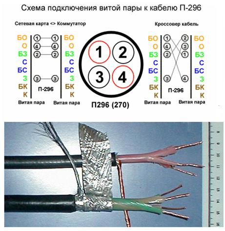
The field cable P-296 is quite well suited for outdoor wiring. In addition to the fact that its insulation is not afraid of water, high and low temperatures, the cable itself is very durable (withstands loads of up to 200 kilograms) and can be stretched without a support cable for a length of up to 100 meters. An undeniable advantage is that using the P-296, you can provide stable communication on a network segment of up to 500 meters.
By its origin, P-296 is an army communications cable. It has 4 insulated cores, a screen, a protective steel braid (mesh of hardened wire) and an outer plastic sheath. The cable is unpretentious in a military way: The maximum connection length is up to 500 meters. Data transfer speed 10-100 Mbit/s.
Withstands a maximum of 200 kg at break, so it can be suspended without a cable at distances of 50-100 meters. The cable can be laid for a long time in the ground, on the ground, suspended on supports or local objects, as well as laid through water barriers with a depth of no more than 10 m.
Comparative characteristics of network conductors
| Cable type (10 Mbps = approx. 1 MB per second) |
Data transfer rate (megabits per second) | Max official segment length, m | Max unofficial segment length, m* | Possibility of restoration in case of damage, extension of length | Susceptibility to Interference | Price |
| twisted pair | ||||||
| Unshielded Twisted Pair | 100/10/1000 Mbit/s | 100/100/100 m | 150/300/100 m | good | Average | Low |
| Shielded twisted pair | 100/10/1000 Mbit/s | 100/100/100 m | 150/300/100 m | good | Low | Average |
| Field cable P-296 | 100/10 Mbit/s | —— | 300(500)/>500 m | good | Low | High |
| Four-wire telephone cable | 50/10 Mbit/s | —— | No more than 30 m | good | High | Very low |
| Coaxial cable | ||||||
| Thin coaxial cable | 10 Mbit/s | 185 m | 250(300) m | Poor Requires soldering | High | Low |
| Thick coaxial cable | 10 Mbit/s | 500 m | 600(700) | Poor Requires soldering | High | Average |
| Optical fiber | ||||||
| Singlemode optical fiber |
100-1000 Mbit |
Up to 100 km | —- | Specialist required equipment |
Absent | |
| Multimode optical fiber |
1-2 Gbit | Up to 550 m | —- | Specialist required equipment |
Absent | |
*- Data transmission over distances exceeding standards is possible when using high-quality components.
We lay the network over long distances
Stable communication when using twisted pair cable at a speed of 100 Mbit is maintained at a distance of up to 100 meters, 10 megabits up to 500.
High-quality network equipment will allow you to increase the length of the segment by another 30-50 meters.
If you use field cable P-296 or similar as a network conductor, the stable range can reach 500 meters at a speed of about 80 Mbit, and about 700 meters - 10 Mbit.
Before installing the cable, you can test a segment of non-standard length; to do this, simply connect two computers standing next to each other with the same cable that you will be pulling, and run a set of standard tests. Thus, it is possible to determine in advance the characteristics of the future network branch before direct wiring, this will save a lot of effort and money. Of course, you need to remember that a cable resting peacefully in your home is not exactly the same as the same cable stretched on a cable. This test does not take into account electromagnetic interference and other external factors. Therefore, its results can be considered only as indicative.
If you need to lay a longer section of the network, for example, to combine 2 networks into one or connect to a remote but somehow valuable computer (for example, with a dedicated Internet channel), then you can install a switch so that it acts as a signal amplifier. Thus, the length of the segment doubles, and when installing two switches, it triples. You can see the topology of such a network more clearly in the following diagram.

The cable braid must be grounded, otherwise it will not perform its functions well. Due to the greater thickness of the conductors, P-296 is difficult to crimp, so in any case, it will be necessary to attach twisted pair sections to the ends of P-296 for crimping. Therefore, P-296 is best used in open areas, in offices, apartments or entrances, switching to twisted pair.
Computers on the local network have their own local IP addresses, but only one server IP address is visible from the outside. This may cause some programs to crash, for example MSN Messenger may not be able to provide advanced video/audio features. Also, if one of the users on your network behaved incorrectly on the server, then his IP will be blocked, and since the server has one IP address for all, access will be denied to all users. Such situations arise especially often in large networks. The solution to this problem lies in controlling the human factor and clearly developing the rules of your LAN. When using NAT routers, some Internet providers allow you to allocate individual IP addresses to each network user; it is worth discussing this issue when connecting.
Crimp twisted pair
Many people believe that this is the most difficult stage of network installation. It's actually simple. To crimp twisted pair cables, you will need special pliers and a pair of RJ-45 connectors

RJ-45 crimping tool

RJ-45 connector
Sequence of actions when crimping:
1. Carefully cut the end of the cable, preferably using the cutter built into the crimping tool.
2. Strip the insulation from the cable. You can use a special knife to strip the insulation of a twisted pair; its blade protrudes evenly to the thickness of the insulation, so you will not damage the conductors. However, if you don’t have a special knife, you can use a regular one or take scissors.
Knife for stripping twisted pair insulation.
3. Separate and unravel the wires, align them in one row, while observing the color sequence.
4. Nibble the wires so that a little more than a centimeter remains.
5. Insert wires into the RJ-45 connector
6. Check if you have placed the wiring correctly
7. Make sure all the wires are completely inserted into the connector and rest against its front wall.
8. Place the connector with the installed pair into the pliers, then crimp smoothly but firmly.
Advice: Some RJ-45 crimping tools can also crimp RJ-12 telephone connectors.
Conductor color sequence
There are two common color pairing standards: Siemon's T568A and AT&T's T568B. Both of these standards are absolutely equivalent.
Circuit for crimping a twisted pair cable (and two computers directly*)
We ask you to pay your attention to the connector; the figure shows the correct location and the beginning of the first wire.

If your cable contains only two pairs:

For eight-core cable (four pairs). The choice of termination option 568A or 568B depends solely on what is accepted in your network. Both of these options are equivalent. It is recommended to use the first one.

Two network connections on one cable
Using one cable, you can connect 2 computers at once, this will save you from wiring another branch of purchasing another switch or additional network card. Simply unravel the conductors and crimp according to the diagram below.

It is important to understand that these are simply two cables compressed into one.
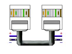
White-blue and blue contacts can be used in a number of cases to transmit power.
Any engineering communication, including a computer network, consists of various components and the local network cable is one of the main ones, on which the speed of signal transmission and its safety from interference, attenuation, and loss of data packets directly depends.
Nowadays, new cable-free data transmission technologies have emerged, such as Wi-Fi and Bluetooth, which transmit data packets via radio wave signals, but these technologies are far from perfect and have a limited range. In addition, the data transmission speed is lower, and interference often occurs during data transmission, therefore a local network via cable is very popular as it is more reliable and fast.
However, there are different types of cables: there are two-core and multi-core cables, twisted and straight cables, solid or multi-core cables, with and without interference protection, etc., etc. And speed, reliability, etc. depend on all these nuances. cable length without signal amplifier. Today we can distinguish the following types of cables for local computer networks:
- coaxial network cable;
- twisted pair network cable;
- fiber optic network cable.
All these types of LAN cables are completely different structure and technological parameters, but they are united by what happens with their use, and this is a separate article. A separate master class is also on how to connect a cable to a plug in a local computer network with your own hands. Well, then we will look at all these types of cables, their parameters, as well as their advantages and disadvantages.
Coaxial network cable
The oldest type of cable, which is practically not used in modern computer networks, is a coaxial network cable. Its extinction is due to the high cost and low data transfer speed, however, if you decide to lay a network of coaxial cable, then the most successful would be to implement it with a “bus” topology. Star and passive star topologies are also good choices.
Contains coaxial network cable of two cores: the central core is solid copper (in a very rare standard, multi-core and/or made of alloys, copper with silver plating), which is represented by the core of the cable, wrapped in thick insulation - dielectric, it is foamed polyethylene.
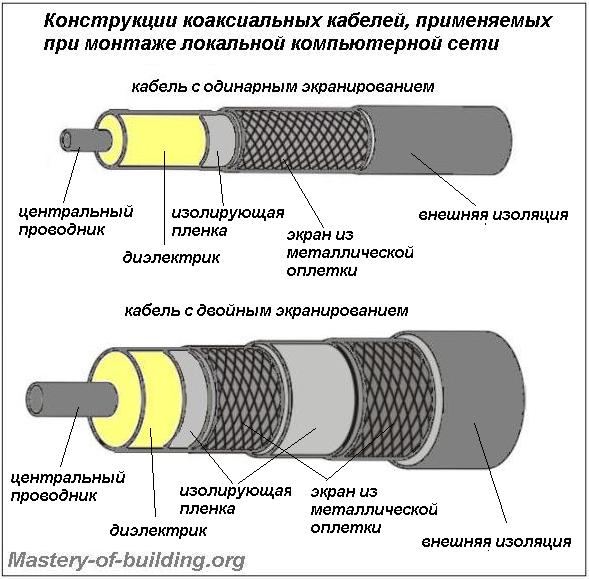
Along this insulation there is a weaving of the so-called “external” conductor, which consists of copper, its alloy or aluminum. It is also referred to as a screen. In this case, there may be varieties of cable with a double screen, when one weave is separated from the other by an additional thin layer of insulation.
The protective sheath of the outer conductor is made mainly of polyethylene or polyvinyl chloride, which is resistant to ultraviolet radiation, but there are expensive cables with a Teflon sheath.
The types of coaxial cable are varied and there are many of them, but specifically coaxial cable for a local network differs in two standards for packet data transmission:
- 10BASE-5 (categories RG-11 and RG-8);
- 10BASE-2 (categories RG-58/U, 58A/U).
Standard 10BASE-5 implemented using a “thick Ethernet” cable having a total cross-section of 12 mm and a thick solid conductor core, category 11 has a resistance of 75 Ohms, category 8 – 50. Cables of this standard could transmit data at a speed of 10 Mbit/s over a distance from now on up to 500 m.
10BASE-2 standard implemented using a “thin Ethernet” cable, up to 6 mm in diameter, with a resistance of 50 Ohms. Its category RG-58/U has a solid (solid) copper center conductor, 58A/U is presented with a stranded center conductor. The data transmission length of cables of these categories is within 185 m with a maximum data transmission speed of up to 10 Mbit/s.
Benefits of Coaxial Cable lies in its effective shielding, which allows it to be carried out over long distances and eliminates interference, as well as high strength, which reduces the risk of mechanical damage to the cable. In addition, the coaxial cable is easy to install; you can attach plugs, doubles and other parts with ordinary hand tools.
Disadvantages of coaxial cable are low bandwidth when used in local computer networks; against this background, a significant drawback is the high cost of the cable itself and plugs/doubles/adapters and other components. Plus, network cards for this type of cable are practically no longer produced; switches and hubs for them are considered obsolete.
Twisted pair network cable
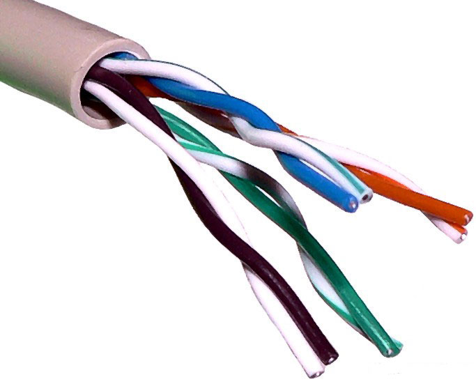
The modern and most commonly used cable for local computer networks is twisted pair cable. It is used in both home and administrative local networks with a star topology and has an excellent price/quality ratio. That is, a network cable for a local network of this type has a relatively high data transfer speed in relation to coaxial cable, while their cost is not high.
The network cable consists of twisted pair for local networks of four pairs of monolithic copper conductors, each with a cross-section of 0.4-0.6 mm. The thickness of the core of such a cable is 0.51 mm, taking into account the thickness of the conductor insulation - 0.2 mm. The insulation material is used in budget options The cable is polyvinyl chloride (designation - PVX), more expensive cables use polypropylene and polyethylene (designation - PP and PE) and the highest quality twisted pair cables are made with foamed polyethylene or Teflon insulation.
According to the degree of protection against interference, it can be: unshielded cable and shielded twisted pair cable. Shielding can be made of wire mesh, aluminum foil/aluminized film, both individual pairs and the entire bundle together.
There are cables with the following types of shielding:
- twisted pair cable (UTP) not protected by any shield at all;
- unprotected by a common shield with pair shielding with foil (U/STP);
- with foil overall shield without shielding individual pairs (FTP);
- with wire screen of each pair and common screen wire (STP);
- with a foil screen for each pair and a common braided screen (S/FTP);
- with double overall screen made of braided wire and foil (SF/UTP).
Moreover, all designations contain “TP” - this indicates the type of cable - twisted pair (from English - twisted pair). Those letters that go ahead actually indicate the presence/absence of shielding, the type of shielding, as well as the material from which the shielding is made. Thus, the letter U (Unshielded) indicates the absence of screen protection, F (Foiled) - indicates the presence of a common foil general screen insulation of the entire bundle of pairs, S (Shielded) - a screen in the form of a wire braid of each individual pair and (Screening) - a screen in the form braids of the entire bundle of twisted pairs.
Depending on the length and speed of signal transmission There are different categories of twisted pair (7 in total), while the intended cable for local computer networks starts from the second category, but today they use cable from category 5E starting.
The main difference between the categories of twisted pair cables was previously the number of cores, but starting from the third category and up to the seventh inclusive, all cables have four pairs (8 cores). So, the main difference was the number of turns per unit length, cross-section of the core and resistance, which is a decisive factor on the length and speed of data transfer.
Modern twisted pair cable applied in the following technology standards packet data transmission:
- 100BASE-TX Ethernet;
- 1000BASE-T Ethernet;
- 10GBASE-T Ethernet;
- 40GbE, 100GbE.
100BASE-TX standard was implemented using a CAT cable. 5 (twisted pair category 5), which was capable of transmitting 100 Mbit/s over two pairs and 1 Gbit over four.
1000BASE-T standard Today it is the most common and is used in many local computer networks. For such networks, the most popular category of cable is used - CAT. 5e, the difference from the previous one is a slightly higher throughput of high-frequency signals and the presence of modifications with two (100 Mbit/s) and four (1 Gbit) pairs.
10GBASE-T standard , on which Fast Ethernet and Gigabit Ethernet networks are built, is implemented using a CAT cable. 6, which is capable of transmitting data at a speed of 10 Gbit/s over a distance of 55 m. Gigabit Ethernet can also be implemented on CAT cable. 6a and CAT. 7, which increases the data transmission length to 100m. In this case, the seventh category always has full shielding.
40GbE and 100GbE standard – the most modern and high-speed packet data transmission technologies that are designed for a Gigabit Ethernet network with a CAT cable. 7a. At a data transfer rate of 40 Gbit/s, the transmission length is 50 m, at 100 Gbit/s – 15 m.
Fiber optic network cable
All existing types of cables for local networks are inferior in all characteristics to fiber-optic network cables. However, its cost and complexity of installation do not make it widely used; it is mainly used to connect local networks over long distances.

Represents a fiber optic network cable conductor of light. Light is transmitted in such a cable through glass or plastic conductors, reflecting from the inner walls. There are fiber optic types of computer network cables, which are distinguished by the diameter of the glass fiber core, respectively, and by the method of transmitting light signals:
- single-mode;
- multimode.
Single-mode fiber optic cables have a glass fiber core diameter of 7-10 microns. Due to such a thin diameter, the fiber is designed to carry single-mode radiation.
Multimode fiber optic cables have glass fibers with a core whose diameter according to the European standard is 50 microns, 62.5 microns - according to Japanese and North American standards. Accordingly, several modes pass through such cores at different refractive angles.
Advantages of fiber optic cable are that the transmission speed is simply phenomenal - theoretically, there is no network equipment today that could support the data transfer rate that a fiber optic cable is capable of. In addition, interference for such a cable is not at all terrible.
Disadvantages of fiber optic cable very significant: the high cost of the cable and auxiliary, installation and network elements for it. In addition, installation of such a cable requires special tools and the qualifications of a cable technician. Thus, it is not advisable to choose a cable for a local network in favor of optical fiber; accordingly, we will not consider all its characteristics.
Twisted pair is a type of communication cable that consists of one or more pairs of insulated conductors twisted together (with a small number of turns per unit length) to reduce mutual interference during signal transmission, and covered with a plastic sheath. One of the components of modern structured cabling systems. Used in telecommunications and computer networks as a network media in many technologies such as Ethernet, ARCNet and Token ring.
Currently, due to its low cost and ease of installation, it is the most common for building local networks.
(the dividing cord is visible between the pairs)
Depending on the presence of protection - an electrically grounded copper braid or aluminum foil around twisted pairs, the types of this technology are determined:
Unshielded twisted pair (UTP - Unshielded twisted pair)
Shielded twisted pair (STP)
Foiled twisted pair (FTP)
Foil shielded twisted pair (SFTP - Shielded Foiled twisted pair)
In some types of shielded cable, protection can also be used around each pair, individual shielding. Shielding provides better protection from electromagnetic interference, both external and internal, etc. The entire length of the screen is connected to a non-insulated drain wire, which unites the screen in case of division into sections due to excessive bending or stretching of the cable.
In addition to this, the cable is used single and multi-core. In the first case, each wire consists of one copper core, and in the second - of several.
A single-core cable does not require direct contact with connected peripherals. That is, as a rule, it is used for laying in boxes, walls, etc. followed by termination with sockets. This is due to the fact that copper strands are quite thick and with frequent bending they quickly break. However, such conductors are ideally suited for “cutting into” the connectors of socket panels.
In turn, a multi-core cable does not tolerate “cutting” into the connectors of socket panels (thin cores are cut), but behaves well when bent and twisted. Therefore, multi-core cable is used mainly for the manufacture of patch cords (PatchCord), connecting peripherals to sockets. In addition, stranded wire has less resistance to high-frequency signals (Skin effect).
Cables based on twisted pair copper unshielded are divided into 5 categories according to their electromechanical properties.
Category 1 cable is used in cases where data transfer speed requirements are minimal. It is typically used for analog and digital voice and low-speed data transmission.
Category 3 cable was standardized in 1991. Then the Standard for Telecommunications Cabling Systems for Commercial Buildings (EIA-568) was developed, and subsequently the EIA-568A standard was created on its basis. This standard defines the electrical characteristics of Category 3 cables at 16 MHz, allowing this cable to be used for high-speed networking applications. Category 3 cable is designed for both data and voice transmission. The twisting pitch of the wires is three turns per 30.5 cm. Most cable systems in office buildings are built on the basis of this cable, through which voice and data are transmitted.
Category 4 cable is an improved version of the previous category. This cable must withstand tests at a signal transmission frequency of 20 MHz, while providing good noise immunity and low signal loss. This category is well suited for systems with extended distances of up to 135 meters, as well as Token Ring networks with a throughput of 16 Mbps. However, in practice it is almost never used.
Category 5 cable is specifically designed to support high-speed protocols. Their characteristics are determined in the range up to 100 MHz. Most high-speed standards are oriented towards Category 5 cable. It supports protocols with a data transfer rate of 100 Mbit/s FDDI with the physical standard TP-PMD, Fast Ethernet, 100VG-AnyLAN and faster ATM protocols with a speed of 155 Mbit/s, as well as a Gigabit Ethernet option with a speed of 1000 Mbit/s. A twisted-pair version of Gigabit Ethernet using 4-core UTP cable became the standard in 1999. Category 5 cable has replaced Category 3, and large building cabling systems are now built using this type of cable in combination with fiber optic cable.
UTP cables are available in 2- and 4-pair versions. Each pair of such cable has its own twist pitch and a specific color. In the 4-pair version, two pairs are for data transmission and two more are for voice transmission.
To connect the cables, RJ-45 sockets and plugs are used, which are eight-pin connectors and look similar to telephone connectors.
The main purpose of this cable is to support high-speed protocols over cable sections longer than Category 5 UTP cable, the maximum segment length of which should not exceed 100 meters. Category 7 cable is hardly advisable for use: the cost of a network based on it is close to the cost of a fiber-optic network, and the characteristics of fiber-optic cables are higher. Therefore, it is likely to gradually disappear in the near future, remaining only in the history of cable development.
Cables based on shielded twisted pair STP protect the transmitted signals well from external interference. The grounded screen used in this type of cable complicates installation, as it requires high-quality grounding and increases the cost of the cable itself. Shielded cable is used for data transmission only.
The main standard defining the parameters of shielded twisted pair cables is the IBM proprietary standard. In this standard, cables are divided not into categories, but into types (Type 1-type 9). Of these, the main one is the Type 1 cable. It consists of two pairs of wires and a conductive shielding braid, which is grounded. STP Type 1 cable is included in international standards.
Shielded pairs are also used in Type 2 cable. This cable is similar to Type1, with the addition of two pairs of unshielded wires for voice transmission. These cables are connected to the equipment using connectors designed by IBM.
Not all IBM standard cables are shielded. For example, Type 3 defines the characteristics of unshielded telephone cable, and Type 5 defines fiber optic cable.
Almost no local network can do without wired segments, where computers are connected to the network using cables. In this material you will learn what types and types of cables are used to create local networks, and you will also learn how to make them yourself.
Almost no local network, be it home or office, can do without wired segments where computers are connected to the network using cables. This is not surprising, because this solution for transferring data between computers is still one of the fastest and most reliable.
Types of network cable
In wired local networks, a special cable called “twisted pair” is used to transmit signals. It is called that because it consists of four pairs of copper strands twisted together, which reduces interference from various sources.
In addition, the twisted pair has a common external dense insulation made of polyvinyl chloride, which is also very little susceptible to electromagnetic interference. Moreover, on sale you can find both an unshielded version of the UTP cable (Unshielded Twisted Pair), and shielded varieties that have an additional foil shield - either common for all pairs (FTP - Foiled Twisted Pair), or for each pair separately (STP - Shielded Twisted Pair).
Using a modified twisted pair cable with a screen (FTP or STP) at home only makes sense when there is high interference or to achieve maximum speeds with a very long cable length, which should preferably not exceed 100 m. In other cases, a cheaper unshielded UTP cable, which can be found, will do at any computer store.
Twisted pair cable is divided into several categories, which are marked from CAT1 to CAT7. But you shouldn’t be immediately afraid of such diversity, since for building home and office computer networks, mostly unscreened cables of the CAT5 category or its slightly improved version CAT5e are used. In some cases, for example, when the network is laid in rooms with large electromagnetic interference, you can use a sixth category cable (CAT6), which has a common foil screen. All of the categories described above are capable of providing data transmission at speeds of 100 Mbit/s when using two pairs of cores, and 1000 Mbit/s when using all four pairs.
Crimping schemes and types of network cable (twisted pair)
Twisted pair crimping is the process of attaching special connectors to the ends of a cable, which use 8-pin 8P8C connectors, which are usually called RJ-45 (although this is somewhat misleading). In this case, the connectors can be either unshielded for UTP cables or shielded for FTP or STP cables.

Avoid purchasing so-called plug-in connectors. They are designed for use with soft stranded cables and require some skill to install.
To lay the wires, 8 small grooves are cut inside the connector (one for each core), above which metal contacts are located at the end. If you hold the connector with the contacts up, the latch facing you, and the cable input is facing you, then the first contact will be located on the right, and the eighth on the left. Pin numbering is important in the crimping procedure, so remember this.
There are two main schemes for distributing wires inside connectors: EIA/TIA-568A and EIA/TIA-568B.

When using the EIA/TIA-568A circuit, wires from pins one to eight are laid out in the following order: White-Green, Green, White-Orange, Blue, White-Blue, Orange, White-Brown, and Brown. In the EIA/TIA-568B circuit, the wires go like this: White-Orange, Orange, White-Green, Blue, White-Blue, Green, White-Brown and Brown.
For the manufacture of network cables, used when connecting computer devices and network equipment to each other in various combinations, two main cable crimping options are used: straight and crossover (crossover). Using the first, most common option, cables are made that are used to connect the network interface of a computer and other client devices to switches or routers, as well as connect modern network equipment to each other. The second, less common option is used to make a crossover cable, which allows you to directly connect two computers through network cards, without the use of switching equipment. You may also need a crossover cable to connect old switches into a network via up-link ports.
What to make straight network cable, it is necessary to crimp both ends the same scheme. In this case, you can use either option 568A or 568B (used much more often).
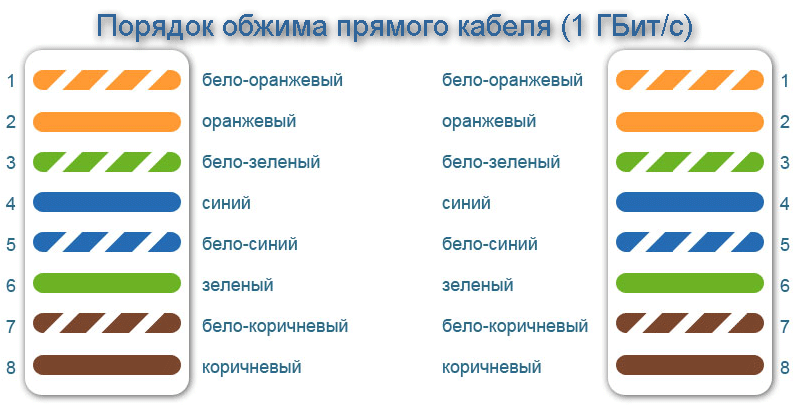
It is worth noting that to make a straight network cable it is not at all necessary to use all four pairs - two will be enough. In this case, using one twisted pair cable, you can connect two computers to the network at once. Thus, if high local traffic is not planned, the wire consumption for building a network can be halved. However, keep in mind that at the same time, maximum speed Data exchange on such a cable will drop 10 times - from 1 Gbit/s to 100 Mbit/s.

As can be seen from the figure, in in this example Orange and Green pairs are used. To crimp the second connector, the place of the Orange pair is taken by Brown, and the place of Green by Blue. In this case, the connection diagram to the contacts is preserved.
For the manufacture of crossover cable necessary one crimp its end according to circuit 568A, and second- according to the 568V scheme.

Unlike a straight cable, all 8 cores must always be used to make a crossover. At the same time, a crossover cable for data exchange between computers at speeds of up to 1000 Mbit/s is manufactured in a special way.

One end of it is crimped according to the EIA/TIA-568B scheme, and the other has the following sequence: White-green, Green, White-orange, White-brown, Brown, Orange, Blue, White-blue. Thus, we see that in circuit 568A the Blue and Brown pairs have swapped places while maintaining the sequence.
Finishing the conversation about circuits, we summarize: by crimping both ends of the cable according to the 568V circuit (2 or 4 pairs), we get straight cable to connect a computer to a switch or router. By crimping one end according to circuit 568A and the other according to circuit 568B, we get crossover cable for connecting two computers without switching equipment. The manufacture of a gigabit crossover cable is a special issue, where a special circuit is required.
Crimping a network cable (twisted pair)
For the cable crimping procedure itself, we will need a special crimping tool called a crimper. Crimper is a pliers with several working areas.

In most cases, knives for cutting twisted pair wires are placed closer to the tool handles. Here, in some modifications, you can find a special recess for stripping the outer insulation of the cable. Further, in the center of the working area, there are one or two sockets for crimping network (marking 8P) and telephone (marking 6P) cables.
Before crimping the connectors, cut a piece of cable of the required length at a right angle. Then, on each side, remove the common outer insulating sheath by 25-30 mm. At the same time, do not damage the own insulation of the conductors located inside the twisted pair.
Next, we begin the process of sorting the cores by color, according to the selected crimping pattern. To do this, unravel and align the wires, then arrange them in a row in the desired order, pressing them tightly together, and then cut the ends with a crimper knife, leaving approximately 12-13 mm from the edge of the insulation.

Now we carefully place the connector on the cable, making sure that the wires do not get mixed up and that each of them fits into its own channel. Push the wires all the way until they rest against the front wall of the connector. With the correct length of the ends of the conductors, they should all fit into the connector all the way, and the insulating sheath must be inside the housing. If this is not the case, then remove the wires and shorten them somewhat.

After you have placed the connector on the cable, all that remains is to fix it there. To do this, insert the connector into the corresponding socket located on the crimping tool and smoothly squeeze the handles until they stop.
Of course, it’s good when you have a crimper at home, but what if you don’t have one, but you really need to crimp the cable? It is clear that you can remove the outer insulation with a knife, and use ordinary wire cutters to trim the cores, but what about the crimping itself? In exceptional cases, you can use a narrow screwdriver or the same knife for this.

Place a screwdriver on top of the contact and press it so that the teeth of the contact cut into the conductor. It is clear that this procedure must be done with all eight contacts. Finally, push the central cross section to secure it in the cable insulation connector.
And finally, I’ll give you a little advice: Before crimping the cable and connectors for the first time, buy with a reserve, since not everyone can perform this procedure well the first time.


