During the gluing process, my garage was filled with a very pungent smell. Therefore, I actively used a large fan. Unfortunately, the summer was rainy and stuffy. This chemical smell hung in the garage, made its way into the house and I got a butt from my wife... it seriously bothered me. Eh, if only I knew what stupidity I'm doing...
Let's move on to drawing. The task is creative, the work is clean, the wife is happy. We put the plywood on the floor and start drawing. If you have a flat floor, you are lucky, it will be easier for you. It’s worth finding a long strip because no ruler will help here, the dimensions are wrong. We transfer the drawing to plywood:
Note to the owner: When drawing curves, a flexible strip and some small nails will help you a lot. Nail the rail at the required points, bending it as you want and draw beautiful lines.
Naturally, I drew both sides, but when I cut out the first one, I realized that I didn’t have to draw the second one, but just attach it and trace the first one :-)
And now the fun part. When it becomes clear that all these “dances with a tambourine” were not just like that. When the outlines appear and the fighting spirit is strengthened... “sew and glue!” In half an hour, a pile of chopped plywood turns into THIS:
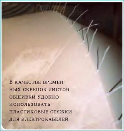
I “stitched” it together with plastic ties. I spotted this method from the bourgeoisie. I managed without wire at all, although closer to the nose the ties broke and I had to install them much more often. In addition to ease of installation, zip ties have another advantage - they do not need to be pulled out. When everything is glued together and the seams are sanded, not a trace will remain of the screeds. No bumps.
Somewhere I “messed up” and as a result, the forespigel did not fall into place. I had to straighten the jambs a little and cut a new forespigel “in place.” It turned out that in my project the froshpigel is tilted a little more than in the original.
It’s worth immediately gluing the strips onto the semi-bulkheads, since they are needed not only as seat support, but also as an element of rigidity. I didn't do this, and realized that I was wrong when I tried to squeeze a bendable piece of plywood between the sides.
For the transom, I bought “Russian plywood” from the same hardware store. This is really a five-layer birch FSF Made in Russia (that’s exactly what it says on the stamp). Plywood is sold in sheets of 5 feet by 5 feet. The remainder went to the aft and center benches (banks).
He began to slowly peck at it, trying to imitate something like a “fillet”:
Further horror and sadness due to one’s own stupidity and ignorance. I bought the resin at an auto parts store in liter cans + a tube of hardener. It was necessary to mix in a ratio of one to one hundred (!!!) and it was terrible. It was simply impossible to maintain the proportion! It hardened instantly (two or three minutes), and the stink was... simply unbearable! I persistently mixed it with wood powder from a sanding machine and filled the joints. I threw away half of each can because it hardened much faster than I had time to do anything. But the worst thing is the smell. I moved into the yard, but that didn’t help much either. Even the neighbors started looking at me angrily. On top of that, I was being eaten alive by mosquitoes in the yard. A few days later I began to have thoughts about taking it all to a landfill and forgetting it like a bad dream. I thought about those who built boats in apartments, about those who glued entire hulls from fabric and resin. How do they do it? After all, this is not real! This is impossible to endure, especially in an apartment. With these thoughts, I wandered around the forums looking for answers, and suddenly I realized that what I was using was NOT EPOXY resin! This is a POLYESTER resin that is used for car repairs!!! That same day I went to a special "boat"
Although building a motorboat with plywood sheathing and a traditional hull design - with a transverse frame and longitudinal beams along the grooves on the keel, chine and along the upper edge of the side - is not too difficult, it still requires certain skills, care and precision when working. First, the builder will have to mark the outlines of the frames in full size - break out the plaza, then assemble frame frames or strong assembly patterns along the plaza, finally - build a strong slipway, accurately align on it and align the entire transverse set, and then the longitudinal set (keel, stringers, fenders), remove the fender from the slats, and only after this can you begin to adjust the outer skin sheets and install them in place. In general, the work turns out to be quite labor-intensive; it is required to occupy any assembly space for a long time, which can pose a problem for a city dweller.
Meanwhile, there is a simpler technological method for assembling small plywood boats, which does not require the manufacture of a slipway and large number transverse frames or patterns - building a boat using the “sew and glue” method. This method, using copper wire clips and fiberglass tapes, has been successfully tested by our amateur shipbuilders in the construction of small rowing and sailing boats (see, for example, the description of the construction of a yacht boat) or the “Crab” boat). We suggest using the same “sew and glue” method to build a four-seater motor boat.
The difference between this method of building boats using the “sew and glue” method from the traditional one is that the contours of the boat hull are obtained during its assembly thanks to pre-cut sheets of skin, and the assembly of the hull consists of joining these sheets along the edges. In this case, there is no need to build a slipway - a flat floor surface or outdoor area is sufficient. The work itself no longer requires great skill. The time the housing remains indoors during the assembly process can be reduced to a minimum. All blanks and parts can be stored in an apartment in a “flat form” and take the three-dimensional shape of a ship in literally 3-4 working days.
"Catfish" - small cabin motorboat with moderately keeled bottom contours, which can be used for fishing trips or for weekend tourism. “Faceted” hull contours, made up of long sheets of outer plating and deckhouse coamings, make it possible to apply the above-mentioned stitching method and at the same time ensure sufficient rigidity of a practically non-studded hull. The hull's shape and strength are given by the cabin bulkhead, just one frame, transom, and the structure of the aft sofa and engine niche. The bottom sheets, after the skin is assembled, are supported by four stringer slats and intermediate floor supports for the flooring. This is necessary so that when sailing in rough seas, the plywood bottom does not begin to act like a thin membrane: with constant repeated bending of the skin plates, the fiberglass joints along the grooves - along the keel and chine - may, if not collapse, then lose their tightness.
increase
1 - internal lining of coaming and recess, δ=6; 2 - facing strip, 15x25, oak; 3 - rail 25x25; 4 - 25x30 rail for fastening the steering seat; 5 - plexiglass, δ=5~6; 6 - breshtuk δ=20, pine; 7 - stem, δ=24; 8 - beam 16x60; 9 - support rail 25x30; 10 - rail 16x32; 11 - bed flooring, δ=4~6; 12 - floor 20x135; 13 - bottom stringer, 20x25; 14 - flooring of the engine niche; 15 - rail 16x55; 16 - knitsa, δ=6; 17 - rail 16x32; 18 - 16x55 beams, glued together from nine 16x6 slats; 19 - door post, 16x55; 20 - transom trim 32x32; 21 - transom, δ=8~12; 22 - transom bracket, δ=6; 23 - under-engine board, 160x32; 24 - rail 25x25; 25 - collar 25x25, oak; 26 - rail 20x25; 27 - locker bulkhead, δ=4~6; 28 - wheelhouse coaming, δ=6; 29 - side plating sheet; 30 - bottom plating sheet; 31 - lining edge, 16x75.
increase
For cladding, it is advisable to purchase five-layer (aviation) waterproof plywood 6 mm thick. You will need 14-15 sheets of standard sizes 1525x1525 mm.
The work begins by connecting all sheet blanks to the required length. The best way- glue the sheet together using epoxy glue (or another waterproof glue) “on the mustache”; necessary recommendations can be found in a book or, for example, in an article about the construction of the “Flying Fish” windsurfer, published in “KiYa” No. 82. Then, on the inside of each sheet, straight, mutually perpendicular lines are applied to mark the contours according to the sketches provided; these lines will also be necessary for control during subsequent assembly of the housing. Smooth curved edges can be drawn along the intended points using a thin flexible strip at least 3 m long.
The sheets are cut along the edges with a fine-toothed hacksaw and planed with a plane so that when stitching, the edges are joined with as little gap as possible; the planes of the ends of the plywood have to be cut “at an angle” (as shipbuilders say, remove the filler from the edges).
From the remains of the plywood sheets, parts of the transom, bulkhead and frame frame are cut out. When assembling the body, these nodes play the role of transverse patterns.
Assembly begins by connecting a pair of bottom skin sheets along the keel groove. Departing from the edge of the keel by 6 mm, a line is drawn on both sheets, which will serve as a center line for drilling holes for wire clips. First, the edges of the sheets to be joined are fastened after 75 mm. At the bow end, where the mating edges form the stem line, it is better to reduce the pitch between the clips. In one of the joined edges, holes can be drilled along the entire length at once, and in the edge of the second sheet, it is better to drill holes in place - sequentially, in sections 500-600 mm long, otherwise when the edges are bent along a curved line, the distances between the holes may turn out to be mismatched.
Paper clips are made of copper wire with a diameter of about 2 mm; Having cut pieces of wire about 40 mm long and bent them in the form of deep brackets, the paper clips are inserted with inside sheathing into the holes and from the outside, twist the ends with pliers. At first, there is no need to try to bring the edges of the joined sheets together too tightly - this will need to be done immediately before gluing the grooves with fiberglass.
Scheme for assembling sheathing sheets using staples using the “stitch and glue” method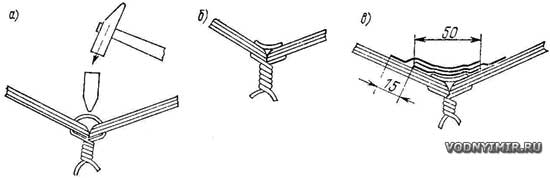
a - wire settling; b - the connection is ready for pasting with plastic;
c - gluing the connection from the inside.
It is better to start installing the clips from the stern, and when the clips stand at a groove length of 1-1.5 m, it is recommended to temporarily install the transom in place - it will help give the bottom the desired deadrise and when further work obtain the correct longitudinal contour of the keel. Later it will also be possible to temporarily “attach” the cabin bulkhead and the frame frame in the bow of the boat. Having gone through the entire keel groove in this way, you need to make sure that the contours are correct and the edges of the plywood fit tightly, and tighten the wire in places where there is an excessive gap.
Housing in process of assembly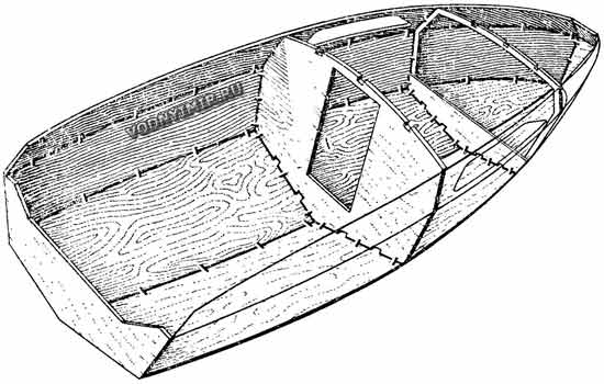
Then both sheets of side plating are put in place; they are grabbed to the exposed set using clamps, a strong cord and nails, and then their edges are connected to the edges of the bottom sheets along the chine, working from the transom in sections of 500-600 mm alternately on both sides.
After tightening the brackets, the temporarily installed transverse set can be removed, having previously marked on the bottom skin the position of the floors, and on the floors, the locations of the cutouts for the passage of the longitudinal slats - stringers. The stringer blanks are placed in place using glue and nails driven through the sheathing in a checkerboard pattern to securely fit the lath to the sheathing along the entire surface. In the nose, where the bend is large, it is better to install rivets or screws.
Staples are more of a mounting element than a fastening of the skin sheets for the entire subsequent operation of the boat. The main strength of the joints is provided by fiberglass, which is formed using thin fiberglass tapes glued with epoxy glue in several layers on both sides of the joint. In order to get a dense layer of fiberglass without air bubbles and peeling from the plywood, it is necessary to carefully embed the staple wire into the wood, which protrudes from the inside of the body in the form of “bridges” over the groove. This can be done using a hammer and chisel with a rounded cutting part or another similar tool; in this case, the seam receives additional compaction.
Gluing the joints begins from the inside of the skin. Before gluing the first fiberglass strip, it is useful to limit the width of the strip lubricated with adhesive by placing adhesive tape on both sides of the groove. A pre-prepared binder (epoxy resin - 100 parts by weight; polyethylene polyamine - 10 parts by weight; dibutyl phthalate - 15 parts by weight, or other components according to the instructions for using the resin available to boat builders) is applied with a brush, then a dry tape of fiberglass In this case, the tape is simply rolled out, but not stretched. From the outside, the fiberglass fabric is tapped with a brush dipped in a binder until the tape is evenly impregnated - it becomes transparent. Air bubbles must be carefully removed, otherwise they will subsequently cause plastic delamination and water filtration.
It is advisable to use factory-made tape - it is widely used for insulation work. You just need to check that the fiberglass fabric is not saturated with lubricant; if it has high humidity, you will have to heat the tape in the oven of a gas stove.
It is enough to apply three layers of tape on both sides of the sheathing to obtain a connection equal to the strength of the plywood. If, when applying the first layer, the binder protrudes from the outside of the joint, this indicates good impregnation of the joint. The layers need to be applied, slightly moving them towards the board in relation to the previous one, so that an overlap of 10-15 mm is obtained along the edge. If you have to cut the fiberglass strips yourself, you can make the top layers wider in advance. The ends of individual pieces of tape should also be overlapped.
When the fiberglass has gelled, you can remove the restrictive adhesive tape and leave the body for a day until the joint has completely hardened.
The next stage of construction is the installation in place (with glue and screws) of the transverse set of the hull and the deckhouse coamings, which are connected to the upper edges of the side plating with staples in exactly the same way as has already been described.
The builder is given the opportunity to choose one of two options for designing the bow end of the boat above the waterline. You can either sew both edges of the sides with paper clips and not install any stem, or make a stem from a board, as shown in the drawing, and attach the bow edges of the sides to it with glue and screws. It all depends on whether the builder likes the blunt bow of the boat or whether he prefers to make it sharp.
Before gluing the grooves from the outside, you need to bite off the protruding twists of wire with pliers as close to the surface of the sheathing as possible, and file the remaining ends of the wire flush with the plywood. Then a limiting adhesive tape is laid along the groove and fiberglass is glued as described above.
Once all the longitudinal connections have been completed, all that remains is to mount the entire structure inside the wheelhouse and cockpit, and then draw in place and staple the roof of the cabin made of plywood 5-6 mm thick. If there are difficulties with the bending of the roof, cut from one solid sheet, it can be cut along the DP and connected to a longitudinal rail - karlengs, which reinforces the roof of the cabin.
It is recommended to cover the outside of the bottom with a continuous layer of fiberglass so that its edges extend to the sides slightly above the cheekbone. When processing all surfaces covered with fiberglass, it should be remembered that the resin layer must not be allowed to be removed and the fiberglass fabric exposed: in this case, the glass threads will begin to filter water through the capillary channels between the fibers and the edges of the plywood in the joints covered with plastic on both sides will soon begin to rot. Therefore, such places should be carefully filled with epoxy putty.
When finalizing the boat, one should not forget about such details as the layouts that form the upper edges of the coamings in the area of the cockpit, transom and recess bulkhead; beads on the sides; metal strip on the stem (it is advisable to extend it along the entire length of the keel). In addition to decorative purposes, these parts protect the body from abrasion and impact, and cover the edges of the plywood from the penetration of moisture between the layers.
D. Antonov, “Boats and Yachts”, No. 83.
“Sew and glue” is new in boat making.
There are, perhaps, no amateur shipbuilders who have not heard of the “Stitch and Glue” technology, or, as is usually translated into Russian, “Sew and Glue,” which allows you to very quickly assemble the hulls of plywood boats of simple shapes from ready-made sheathing patterns with subsequent gluing them with fiberglass.
The method, which does not involve the labor-intensive process of manufacturing a wooden set on a slipway, has existed for about half a century, has been described more than once in specialized and periodical literature (a typical example is given in No. 83 “KiYa”, where the construction of a 4.4-meter motorboat “Som” is described) and has been well developed in our amateur practice in relation to small rowing and motor boats. The real boom that it is experiencing abroad, primarily in the USA, forces us to return to consideration of this technology.

A bunch of small firms and independent designers now offers projects and ready-made kits for the independent construction of small vessels for a wide variety of purposes - from tiny hulls to very impressive 12-14 meter boats and sailing yachts - at a reasonable price (from several tens to several hundred dollars per project), boats are built and serially for sale. There are several reasons for the widespread use of technology. Firstly, boats built using the “SiS” method have revealed their high strength and resource potential, showing that in operation they are superior in practicality to purely wooden vessels, being significantly cheaper than serial fiberglass ones.
Secondly, new materials suitable for gluing plywood bodies have appeared on the market - less toxic and less demanding epoxy resins and composite biaxial* glass tapes. Thirdly, the design of the vessel itself, the hull parts of which unfold onto a plane and fit neatly together, forming a free-standing shell structure, is now developed using a computer and three-dimensional modeling programs.
The plywood parts in the kits sold for DIY boat construction fit together so precisely that even a semi-skilled amateur assembler (and it is for him that such kits are made) is able to build a boat with a guaranteed good result, if, of course, he strictly follows all the points in the assembly manual . When deciding to make a boat using the “SiS” method, an amateur builder must understand that the ideology of its assembly will be somewhat different from the traditional one, which involves the presence of a wooden set covered with plywood.
In a “shit-laminated” body, wooden parts are given a more formative role than a structural one, and the requirements for the quality and design of the joints between wooden parts are correspondingly reduced. But the process of gluing joints, edges, and surfaces with fiberglass requires greater care, as well as maintaining the correct thicknesses and radii of the gluing. The wood of the hull must be completely encapsulated with a layer of resin so that water cannot access it from either the outside or the inside of the hull.
This is the key to the durability of structures: wet plywood begins to change sizes, warp, delaminate, and is also subject to attacks by microflora. Filtration of water through plastic covering is practically impossible - epoxy resins, unlike polyester resins, have extremely low water absorption*. In fact, a “sew-glued” body is an intermediate option between a conventional plywood body, glued on the outside for durability, and a purely plastic one, in which wood is used only to provide additional local rigidity to the structure. The approach to the construction process itself changes accordingly.
If a type-setting building is built in one place gradually and for a long time, with the layout of the plaza, preparation of the slipway, adjustment of each part to minimize gaps, then the sewn body is erected in just a few days on some semblance of a slipway or even on a flat area, allowing gaps between parts, which are selected with epoxy putty without compromising overall strength. But this must require accurate and as complete design and procurement work as possible, preparation of all necessary components, and it is also advisable to have at least one assistant - plywood parts can be of considerable size and thickness, which are not easy to handle alone.
SiS technology is well represented on the Internet, for example, on the websites of Jacques Mertens or Sergei Barkalov. Let us present here its main stages in relation to the 6-meter hull of a planing motor boat, so that readers unfamiliar with “CiS” can appreciate the beautiful simplicity constructive solutions, and those already familiar with it - to find something useful for its further successful use.
1. Preparation of plywood hull parts and equipment - sheathing sheets, frames, bulkheads. Parts are cut from sheets of waterproof plywood using templates or directly according to markings. Most likely, for long parts, sheets of plywood will have to be glued into panels, for which there are conventional methods - gluing “on the mustache” or on a backing strip - this does not affect the strength.
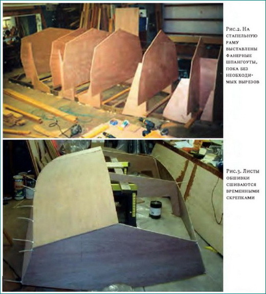
2. Assembling the auxiliary assembly jig. Its base is two flat boards 50x200, the length of the hull, leveled to the width of the boat along the chine. On the base, in accordance with the project, temporary frames and bulkheads, as well as a transom, are placed on racks; a longitudinal set of bottom stringers is inserted into their bottom slots (Fig. 2). The equality of the diagonals is checked with an accuracy of 3 mm.
3. Sheets of the bottom plating are placed and fastened along the keel line with ties - preferably plastic electrical ties - every 150–200 mm. Next, the sheets of side plating are exposed and fastened with ties to the bottom along the cheekbone (Fig. 3). Temporary screws can be used at the transom and stem; It is important that the sheathing does not lag behind the transverse set of equipment.
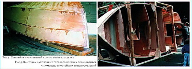
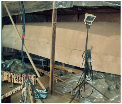
4. Sheathing sheets are joined over the joints with strips of resin-impregnated fabric at intervals of about 300 - 400 mm. After they have cured, the temporary screeds are removed, and the joints are glued on the outside with continuous strips of fiberglass. Next, the entire body is covered with the required number of layers of fabric, and after curing, the surface is brought to condition in the usual way - by puttying and sanding (Fig. 4). After this, you can install overhead elements: fenders and splash guards, if they are provided for in the project. Installation is done using temporary screws, which are removed after the glue has cured.
5. The outside of the hull is coated with high-quality primer, preferably epoxy, and, if tilting upward with the keel is no longer expected, then with a finishing coat of paint. Next, the hull is prepared for edging - a set of equipment is glued to the hull from the inside with temporary tacks and removed from the slipway frame (Fig. 5). If lifting equipment allows, then the set does not need to be glued, but removal of the body from the equipment will have to be done with caution.

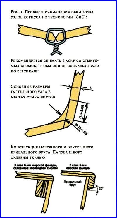
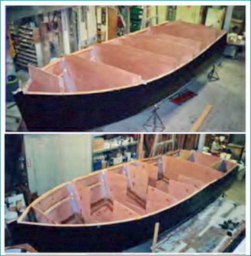
6. The inverted hull is installed on keel blocks, all parts of the set are removed from it and the tacks are sanded off - this makes it easier and more economical to cover it from the inside. The grooves of the sheathing sheets are covered with a layer of epoxy putty (it can be mixed from resin with fine sawdust) to form a radius fillet with a thickness equal to the thickness of the skin (Fig. 1), and are glued with strips of fabric. Then the entire inner surface of the case is covered with the required number of layers.
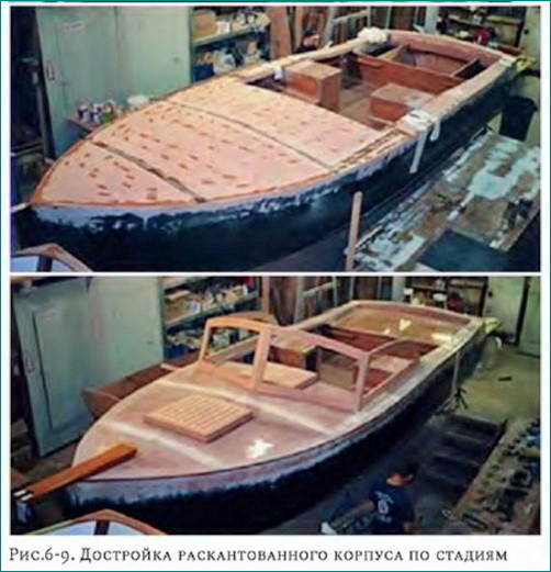
7. The previously removed set is installed into the housing shell (Fig. 6). Since the geometry of the inner surface is changed by gluing the grooves, the corners of the frames should be rounded, but the thickness of the fiberglass coating of the skin will not significantly affect the fit. It is worth taking care in advance about all the necessary cutouts in the kit - for forming a cockpit, installing hatches, water flows, cable wiring, etc. (Fig. 7). The parts of the set must fit smoothly onto the casing, without point contacts with it weakening the structure. Then the joints of the frame and the sheathing are coated with putty to form a fillet and taped with glass tape. It is necessary to take measures to impregnate all unprotected plywood surfaces with resin - after final assembly it will be impossible to do this.

8. Install the deck and gunwale parts with glue, gluing the joints in a similar way (Fig. 8–9). The cockpit and deck are being painted. That's all - the resulting body is durable, and its rigidity is higher than that of wood. The St. Petersburg yacht club “Baltiets” has been building small vessels using the described method for the past three years, several hulls per year, they successfully navigate the city canals, demonstrating enviable endurance - there have been pile-ups of steel barges and impacts on bridge abutments.
According to experience, the labor intensity of building such a 6-meter boat for an experienced team of two people can be only about 40 hours, and the actual assembly work will take 60-70% of the time, cutting and preparing parts - 20 - 25%, and surface treatment - puttying, sanding , coloring - the remaining 10–15%. Of course, as you know, the greatest effort of an amateur builder goes into equipment and interiors, and this fact somewhat neutralizes the advantages of the SiS technology in relation to cabin ships.
But one cannot deny its advantages, such as undemanding builder qualifications, minimal need for special tools (an electric drill, a jigsaw and an angle grinder are enough), and a short rental period for a warm workshop. If these factors are important to you, feel free to take on construction using the “Sew and Glue” method.
Author - Please enable javascript to see email!!!I’ve been thinking for a long time about building a small motor boat to ride around our bay and be able to carry a car on a cart to neighboring bays.
Implementation is hampered, firstly, by laziness, and secondly, by the presence of a small inflatable boat with a 2-horsepower outboard motor, and most importantly, a premonition of all sorts of problems: selection of material, choice of project, search for a place to build, a parking space, etc., I’m not a carpenter or carpenter, I have neither a barn nor a garage . But still, it seems that I have already gotten involved and have begun, theoretically for now, to solve these issues for myself.
How to do?
Once upon a time, in one of the issues of KiYa, I learned about a method of building a boat hull that does not require a slipway, does not require “laying out the plaza,” and does not require “drawing the plating belts in place.” You just need to draw the blanks for the bottom and sides according to the template, then fasten these parts together with wire clips and glue strips of fiberglass with epoxy glue along all the seams. Then insert pre-cut and assembled bulkheads and frames into the ready-made shell and glue them in the same way. A similar project can be viewed at.
Later, from the Internet, I learned that this method is called stitch&glue, that is, “sew and glue,” and that a huge number of home-made people around the world have long and successfully used it to build a wide variety of boats. Even joining sheets of plywood to obtain long pieces is done in the same way, and not by the “miter joint” or “with a backing strip” method. It turns out that without any special woodworking skills, you can build a boat hull relatively easily and quickly! Moreover, all the blanks remain flat until the very moment of assembling the case - they can even be cut out and stored in an apartment.
What to make it from?
Made from plywood, of course! But I have not yet seen waterproof plywood on sale in our city. On one of the forums (unfortunately, now inactive) I read that the guys built several boats for their summer camp site from ordinary construction plywood, covered them with fiberglass and have been sailing on them for several years. It seems to me that this can be quite applied. (In a couple of years, it will most likely turn out that the boat turned out to be not quite “correct” and another one needs to be made.) Another “reason” to postpone construction disappears - there is no waterproof one, you can build it from an ordinary one.
In fact, waterproof plywood is sold in Vladivostok, although it is not always available in every particular store. (Note from the site author.)
What to do?
Since our own operating experience motor boats I don’t have one, I studied with interest the opinions of other, more experienced comrades, I especially liked the discussion of the “people’s boat” on. I decided that I needed a boat 4 - 4.5 m long, 4-seater, with a 30-50 hp motor. Actually, these are exactly the kind of boats that were once produced by Soviet industry. But they don't make them anymore. And it seemed to me that they were not very suitable for the sea.
I have a book, my friends gave it to me, it’s called “15 projects of ships for amateur construction”, probably the very first edition - 1974. In this book there is a project for the Orca motorboat - I liked it. But the technology described in the book is not stitch&glue at all, but the most classical one - no patterns - only a “theoretical drawing” and a “structural drawing of the hull and sections of the frames.” Having read to the phrase: “When marking the 4th and 5th frames and the transom on the plaza, you must first mark the position of the bilge point, then horizontally inward from it the width of the bilge splash guard, and vertically its height and connect the ends...”, I realized that I needed another project.
"Own" project.
And I remembered the website of a certain Robert Lyne that I found several years ago (I’ll call him that because I can’t read French, but he seems to be French). He wrote the program Carene 5.0, designed to calculate patterns for a boat hull made of sheet material - plywood or metal. And he offers this program to all fans free of charge, that is, for nothing. In this program, by setting several parameters - length, width at the midsection and at the transom, deadrise angle, camber angle, etc., you can obtain pairs of XY coordinates using which to draw blanks for the bottom, sides, transom, deck and 80 frames. True, the examples considered displacement hulls for rowing boats or yachts, but I decided to try to transfer the main dimensions of the Orca boat into the program. Here's what happened:
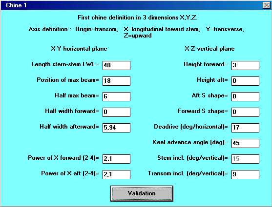
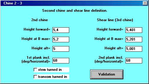
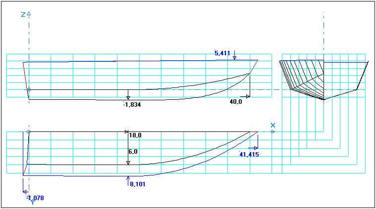
I slightly increased the camber of the sides, and the stem doesn’t look very similar, in general it’s not “Orca” - well, okay, it doesn’t seem to look so bad. It turned out at first glance that from 2 standard (1.22x2.44) sheets of plywood glued together in length, both bottom blanks will be obtained, and from the other two - side blanks.
It will be more beautiful and stronger, but it will take so much extra effort to draw, cut and glue!!! It’s better to make a strong fender later.
Testing on the model.
Again doubts - can you trust these long columns of XY and XYZ coordinates issued by the program? Like these:
Half Transom development created with Carene50 Lower part Y Z 00.00 00.00 01.48 00.46 02.97 00.92 04.45 01.38 05.94 01.84 07.42 02.30 08.91 02, 76 10.39 03.22 11.88 03.68 13.36 04.14 14.84 04.60 19.87 17.22 00.00 17.22 Upper part Y Z 0.000 1.722 1.987 1.722 1.987 1.723 0.000 1, 723EOF
And what else will have to be calculated or completed locally on a real boat?
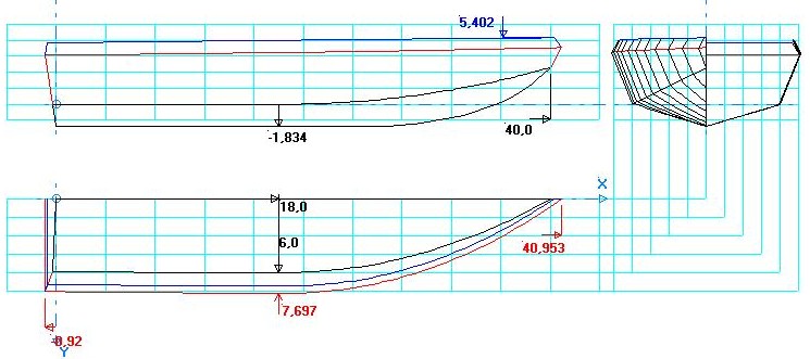
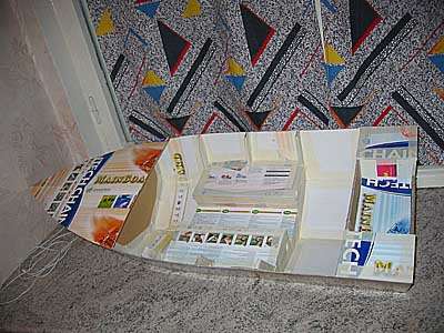
Once, those who wanted to make a boat from AMG were advised to first build a radio-controlled plywood model and test it. The idea seemed good to me, however, I was going to make the boat itself out of plywood. But it would be nice to test it on a model. I entered the data recalculated to a scale of 1:4 into the program and got the result:
All that remains is to collect a bunch of cardboard boxes at work, print out all the necessary tables, buy fresh blades for the knife and - go ahead!
First, I sketched out the location of the practical frames.
From the 80 calculated by the program, I chose 7 pieces that were suitable for the location, drew them and cut them out of thick cardboard.
Then I made blanks for the bottom and sides - long strips of pieces of thin cardboard glued together using "backing strips" - and began drawing points in accordance with the printouts of the coordinates. When drawing the side, I noticed the coincidence of the number of theoretical frames (80 pieces) with the number of points defining the curves in the side pattern drawing. Just in case, I connected the points on the pattern with lines, the numbers of which coincided with the numbers of my practical frames - it looks like these lines set the positions of the frames. Then he began to draw a pattern for the bottom and began to doubt his previous guess - from the stern to approximately the middle of the boat, the lines seemed to coincide with the places where the frames were installed, but further towards the bow they moved somewhere and began to run not across the pattern, but diagonally! I put this problem aside for later.
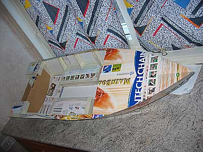
I connected the bottom blanks together, then attached the sides and transom. Instead of metal wire, I used thin strips of paper tape.
Everything coincided!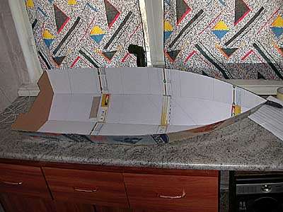
I especially liked how precisely all four blanks fit together in the bow (I glued from stern to bow).
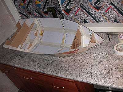
Installation of frames.
Then it was time to install the frames, and then the same problem arose with determining the exact location of their installation. If you do not mark the installation locations of the frames on the pattern, then how to install them later. I didn't find anything about this in the program description. I thought a lot: o)... Then I found Robert Line’s e-mail and wrote him such a letter (the persons who own English language, please don’t laugh too much):
Thank You very much for you CAD software. I want to build my own boat for a long time. Resently I find info about stitch and glue method, and find that it is applicable for me. May be I"ll build a boat next summer. I"m going to use Carene 5.0 for hull designing. I even built 1:4 model of my boat from cardboard - looks fine. But I don"t understand, can I mark places for stations on developed planks, when they are flat yet? First, I thought, that x-coordinate of any plank"s point number fits to corresponding station number. But now I see it"s not right. Does any way exists to draw lines on the planks - where stations will be attached. Yours sincerely. Pavel Kryzhny. Vladivostok, Russia.
A day later the answer came:
Hello Pavel, thank you for the compliment on Carene. If you look at the developed plank files in XYZ format you will notice that there are always 82 points like in the hull line file. The first point 00 is at the transom, point 01 is at the aft end of the keel and then each point up to 81 is at fixed interval along the keel corresponding to 80 stations. The last point is at the stem. The above is true for the side planks. For the bottom the same is true up to the point of maximum beam width. Forward of that the ruling lines are skewed forward by the keel advance angle and points do not correspond anymore to the stations unless the keel advance angle is zero. Attached is a photo of the aluminum boat I built from Carene50 drawing Regards / Amities Robert Laine http://www.sailcut.com Free CAD for sails and hull http://sailcut.sourceforge.net/ Open source code
That is, it turns out that I guessed correctly - the lines I drew on the patterns of the sides are where the frames will be installed. And on the bottom pattern, using the program data, you can mark the installation locations of the frames only from the stern to the midsection. In principle, the lines on the sides are enough - I started installing the frames.
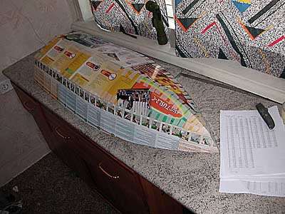
I also cut out the deck and floorplates according to the tables obtained from the program. Needless to say, both the deck and flooring exactly coincided with their installation locations. I measured and cut out the details of the recess and the lockers-stands for the seats according to calculations and auxiliary drawings (it was possible simply “on the spot”)
An interesting observation is that marking, cutting, stitching and gluing the actual “shell” of the hull takes much less time (about 20%) than the subsequent arrangement: frames and bulkheads, deck, recess, lockers and floors, etc.
Installation of redans.
I was so carried away by assembling the hull that I completely forgot about the longitudinal steps: how to mark lines on the bottom for their installation. I had to cut out another bottom pattern for the experiment. From the stern to the midsection, everything is, in general, clear - I divided the width by 3 - and got the coordinates of the lines for 2 steps. And then to the nose? There are 4 main options, and a bunch of intermediate ones.


