In Russian schools, drawing is introduced into compulsory study from the 7th grade. In the first lessons, children learn the basic rules, get acquainted with various graphic methods of transferring an object to the surface of a blank sheet of paper, and perform simple drawings. This lesson has a characteristic effect on the teenager’s thinking, expanding his horizons and attention. In the future, the basics of drawing will definitely come in handy if you want to become a professional engineer, architect, designer, builder, designer or specialist in any other technical profession.
Where does drawing begin?
Drawing for beginners is studied from simple materials, which are the basis and give rise to the skill of being able to produce an accurate drawing, according to given parameters. At the first stage, you need to learn how to perform the most basic tasks related to dividing straight lines into equal parts. This science also includes a detailed study of different-scale geometric shapes and symmetrical patterns. To perform a drawing perfectly, you need not only knowledge, but also accurate vision, as well as convenient special tools for drawing.
A more complex level of drawing begins at the second stage of studying this subject. Its basis is the ability to accurately depict topographic and geographical maps, with the most accurate adherence to scale, color conditions and special symbols. Such complex drawing, as a rule, is studied in specialized educational institutions, with a chosen specialty that requires skills and abilities in this area.
In order to meet the modern requirements of the chosen specialty, which requires mandatory knowledge of this science, many young people are interested in the possibility of studying the subject on their own. As a rule, this problem arises when you want to study for a technical profession, where the ability to correctly draw drawings, diagrams and sketches is simply necessary!
The main goal of teaching drawing for beginners is to consolidate or gain knowledge in the field of a given subject, which at one time was obtained in drawing.
Drawing skills can be acquired in several ways:
Paid courses in drawing;
Individual lessons with a professional tutor on this subject;
Independent study of drawing using computer programs. There are also special sites on the Internet for initial study of the subject, so any interested user can, without the involvement of a teacher, study drawing for beginners in a comfortable mode.
In order to complete even the simplest drawing on paper, it is extremely important to comply with established standards and requirements regarding drawings, to make drawings in established scales, using a specific drawing font.
The first thing to start with is the design of a special drawing frame. For it, it is worth making indents of 5 millimeters at the top, bottom and right, and 20 millimeters on the left for convenient filing of the finished drawing.
The main inscription is located in the lower right corner of the sheet; a special table is drawn for it, 55 millimeters high and 185 millimeters wide. The main table must be filled out in font according to GOST 2.304-81.

Before you begin work, you need to prepare tools, including:
Pencils of different hardness;
- measuring ruler;
- squares;
- preparation room;
- eraser;
- other tools.
The paper is selected in a suitable format; please note that the quality of the drawing printed on it depends on the quality of the paper. You can purchase suitable sheets at any office supply store.
Before you start drawing, you should learn how to write numbers and letters according to GOST. It is advisable to practice on a separate sheet, where you should first draw a special auxiliary grid. Over time, you will develop an eye, and the drawing letters will be the same.
The GOST requirements state that the drawing font, both letters and numbers, must be inclined by 75 degrees.


The letters do not correspond to the sizes specified in GOST;
- all letters different sizes and “jump” in the line;
- the letters have different slants.
To learn how to write a drawing font correctly, at first you can use a compass to draw two lines along the height of the letters. This way the font will be even and the letters will not be of different heights.
Beginners are advised to choose to draw lines with an optimal width of 0.8 to 1 millimeter. Please note that the frame and title block in the drawing should be made with a continuous thick line. A thin solid line will help to draw an image of a section of a part, as well as to make extension dimensions.
Other lines are also used in drawing:
- solid uneven line – intended to indicate the demarcation line in the drawing. It is often carried out when the part is too voluminous and there is no point in placing it entirely;
- shading – invisible lines are indicated;
- hatching with a dotted line - designation of the center of the part or axis.
All main lines in the drawing are made up to 0.3 millimeters thick on formats up to A1, while the thickness of the hatching is selected in accordance with the dimensions of the part. When performing the projection drawing procedure, the following errors and inaccuracies are most often made:
- incorrect shading of details;
- in axonometric projections, the image of circular and ellipse-shaped parts is incorrectly constructed;
- the secant area of the part is selected incorrectly, and therefore it is not possible to consider all the features of the part.
The depicted object is positioned in such a way that all its faces correspond to six projection planes. In this case, the front view (frontal plane) is the main image.

It is best to position the part towards the observer in such a way that a complete picture of the size, shape and other characteristics of the depicted product is created.
Usually in the drawings the part is schematically cut, this is done in order to understand the structure of the part from the inside. This gives a complete picture of cuts, notches and other features that are not visible on the frontal plane.
It is advisable to initially make the image with thin lines that will be easy to remove. It is better to outline the drawing with thick lines at the last stage.
Etc.) documents that individually or collectively define the composition and design of the product, contain the necessary data for its development, manufacture, control, acceptance, operation and repair.
In order to manufacture parts and assemble an assembly unit from them, it is necessary to carefully develop design documentation. It must unambiguously determine what must be manufactured: name of the product, size, shape, appearance, materials, manufacturing methods, etc. Design documentation must ensure the identity of products of the same name during their manufacture and, if necessary, their interchangeability.
Drawings, diagrams and other design documents are carried out according to uniform rules and regulations established by state standards -. State standards have been consolidated into a unified system of design documentation (ESKD).
one system design documentation ( ESKD) - a set of state standards that establish interrelated rules and regulations for the development, execution and circulation of design documentation developed and applied by organizations, enterprises and educational institutions. ESKD takes into account recommendations International organization for Standardization (ISO), Standing Commission for Standardization.
Compliance with state standards is mandatory for all industries, design organizations, scientific institutions etc. All drawings must be made in accordance with ESKD standards and have a clear and neat design.
The standard has letter and number designations.
Formats
Drawings are made on sheets of paper of a certain size, called formats.
The dimensions of the format and its designations are established (Fig. 1, 2).
Rice. 1. Vertical formats

Rice. 2. Horizontal formats
The area of A0 format is approximately 1 m2. Other basic formats can be obtained by successively dividing the A0 format into two equal parts parallel to the smaller side of the corresponding format. In drawing lessons they use, the dimensions of which are 210 x 297 mm.The size of the A4 format (210x297) is taken as the unit of measurement for other formats.
Table 1 shows the sizes of the formats:
|
Format designation |
Dimensions of format sides, mm |
|
A0 |
841×1189 |
|
A1 |
594×841 |
|
A2 |
420×594 |
|
A3 |
297×420 |
|
A4 |
210×297 |
The formats are drawn up with an internal drawing frame, which is applied in accordance with GOST. Draw it with a solid thick main line. At the top, right and bottom, the distance between the lines delimiting the inner and outer frames is taken equal to 5 mm. A 20 mm wide strip is left on the left side for filing and binding drawings (Fig. 3). This makes them easier to store and creates other conveniences.

Rice. 3. Format design
Title block of the drawing
Production drawings made on A4 sheets are placed only vertically, and the main inscription on them is only along the short side. On drawings of other formats, the title block can be placed along both the long and short sides.
In the lower right corner is the main inscription of the drawing, containing information about the depicted product. As an exception, on training drawings in A4 format, the main inscription is allowed to be placed both along the long side and along the short side (Fig. 4).

Rice. 4. Location of the frame and main inscription on the drawing.
GOST 2.104-68 establishes the shape and dimensions of the main inscription. On educational school drawings, the main inscription is made in the form of a rectangle with sides 22x145 mm. Each column of the inscription has a certain size. The main inscription indicates the name of the depicted part, the material from which it is made, the scale, who drew, who checked the drawing, when the work was completed (date), name of the school, class and drawing number.
A sample of the completed title block is shown in Figure 5.

Rice. 5. The title block of the training drawing
Each drawing and graphic document must be executed technically competently and graphically clearly. The drawing must comply with the requirements of the standards and contain all the detailed information necessary for the manufacture of parts.
- " onclick="window.open(this.href," win2 return false >Print
Drawing Basics
You already know that to make any product you need to know its structure, the shape and size of the parts, the material from which they are made, and how the parts are connected to each other. You can find out all this information from drawing, sketch or technical drawing.
Drawing
- This is a conventional image of a product, made according to certain rules using drawing tools.
The drawing shows several types of products. The views are performed based on how the product is viewed: from the front, from above or from the left (side).
The name of the product and parts, as well as information about the quantity and material of parts are entered in a special table - specification.
Often the product is depicted enlarged or reduced in comparison with the original. But despite this, the dimensions shown in the drawing are actual.
The number that shows how many times the actual dimensions are reduced or increased is called scale
.
The scale cannot be arbitrary. For example, for increase
accepted scale 2:1
, 4:1
etc., for decreasing
-1:2
, 1:4
etc.
For example, if the drawing contains the inscription “ M 1:2
", then this means that the image is half the size of the actual one, and if " M 4:1
", then four times more.

Often used in production sketch
- an image of an object, made by hand according to the same rules as a drawing, but without observing the exact scale. When drawing up a sketch, the relationship between the parts of the object is maintained.

Technical drawing -a visual representation of an object, made by hand using the same lines as the drawing, indicating the dimensions and material from which the product is made. It is built approximately, by eye, maintaining the relationships between the individual parts of the object.
The number of views in the drawing (sketch) should be such as to give a complete picture of the shape of the object.
There are certain rules for sizing. For a rectangular part, dimensions are applied as shown in the figure above.
Size
(in millimeters) are placed above the dimension line from left to right and from bottom to top. The name of the units of measurement is not indicated.
Part thickness
denoted by a Latin letter S; the number to the right of this letter shows the thickness of the part in millimeters.
Certain rules also apply to the designation on the drawing. hole diameter
- it is designated by the symbol Ø
.
Circle radii
denoted by a Latin letter R; the number to the right of this letter shows the radius of the circle in millimeters.
Part outline
must be shown on the drawing (sketch) solid thick main lines(visible contour lines); dimension lines
- solid thin; invisible contour lines
- dashed; axial
- dash-dot etc. The table shows Various types lines used in drawings.
|
Read the drawing, sketch, technical drawing - means determining the name of the product, the scale and images of the views, the dimensions of the product and individual parts, their names and quantity, shape, location, material, type of connection.
Technical documentation and harmonization tools
Technical documentation for the manufacture of a simple single-part, multi-part or complex product includes:
image
finished product, specification and brief information about the function ( F), structures ( TO), technologies ( T) and finishing (aesthetics) ( E) of this object of labor - the first sheet;
scheme
possible options changes in the overall dimensions and configuration of the product or its parts. The proposed changes are based on various systems of correlation and division of forms - the second sheet;
parts drawings
complex configurations, which are made according to templates, - the third sheet (not for all products);
illustrative technological map
, containing information about the sequence of manufacturing parts or the product itself in the form of operational drawings and about the tools and devices used to perform this operation - subsequent sheets. Their content may be partially changed. These changes relate mainly to the use of special technological devices that make it possible to speed up the execution of individual operations (marking, sawing, drilling, etc.) and obtain higher quality parts and products.
Development of the design of any product, to appearance which certain aesthetic requirements are presented, is associated with the use of certain patterns, techniques and means of composition. Ignoring at least one of them leads to a significant violation of the form, making the product inexpressive and ugly.
The most commonly used means of harmonization are: proportioning(finding the harmonic relationship of the sides of the product), subordination and division of form.
Proportionality- this is the proportionality of elements, the most rational relationship of parts between themselves and the whole, giving the object harmonious integrity and artistic completeness. Proportions establish the harmonic measure of parts and the whole using mathematical relationships.
A system of rectangles with proportional aspect ratios can be constructed using:
A) integer ratios from 1 to 6 (1:2, 1:3, 1:4, 1:5, 1:6, 2:3, 3:4, 3:5, 4:5, 5:6) (Fig. 1) ;
b) the so-called “ golden ratio" Determined by formula a: в=в:(а+в). Any segment can be proportionally divided into two unequal parts in this regard (Fig. 2). Based on this relationship, the sides of the rectangle can be constructed or divided (Fig. 3);
V) proportional series, composed of the roots of natural numbers: √2, √3, √4" √5. You can construct a system of rectangles of this series as follows: on the side of the square “1” and its diagonal “√2” - a rectangle with an aspect ratio of 1: √2; on the diagonal of the latter there is a new rectangle with an aspect ratio of 1: √3; then a rectangle - 1: √4 (two squares) and 1: √5 (Fig. 4).
To find the harmonic aspect ratio, use the system subordination and division of form:
A) subordination it is used when another element is attached to one element, commensurate with the main part (Fig. 5);
b) dismemberment is used when it is necessary to break the main form into smaller elements (Fig. 6).
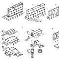
Below are options for changing the shape configuration of products and options for changing overall dimensions, which use the above harmonization rules.


https://www.2d-3d.ru/ - ready-made drawings for more than 70 categories, such as houses, tools, furniture, appliances, cranes, bulldozers, stairs, wooden structures, concrete mixers.
Marking rectangular parts
Purpose and role of marking. The process of applying contour lines of a future workpiece to wood is called marking. Marking- one of the most important and labor-intensive operations, the implementation of which largely determines not only the quality of products, but also the cost of material and working time. Marking before sawing is called preliminary or marking of rough blanks.
In production, preliminary marking is carried out taking into account allowances for processing and drying. In training workshops, dried materials are processed, so allowances for shrinkage are not taken into account.
You should know that when processing dried workpieces, a surface with low roughness is obtained and high adhesive strength and finishing are achieved. Grinding allowances on one side the details of the planed surfaces are equal to 0.3 mm, and for parts whose surfaces are sawn, - no more than 0.8 mm. There are no allowances for planing fibreboards and plywood, since they are not planed.
Marking perform pencil using marking tools (measuring ruler, carpenter's square, surface planer, measuring rod, tape measure, caliper, etc.) in accordance with the drawing, sketch, technical drawing. An overview of some marking tools is shown below.


Marking and measuring tools. As you already know, marking wood and wood materials is carried out with various tools, most of which are also used for measurements during the manufacturing process of parts: roulette- for measuring and marking lumber and timber; meter- for marking rough blanks; ruler- for measuring parts and workpieces; square- for measuring and drawing rectangular parts; erunok- for drawing and checking angles of 45° and 135° and when marking miter joints; fry- for drawing and checking various angles (the given angle is set using a protractor); thicknesser and bracket- for drawing parallel lines when processing edges or faces of workpieces; compass- for drawing arcs, circles and marking dimensions; calipers- to determine the diameter of round holes; bore gauge- for measuring the diameter of holes.

From the accuracy of marking The quality of the product depends. Therefore, be careful when working. Try to mark in such a way that you get as many parts as possible from one workpiece.
Don't forget about allowance. Allowance
- layer of wood that is removed when processing the workpiece(when sawing, they usually give an allowance of up to 10 mm, when planing - up to 5 mm).

When marking a rectangular piece of plywood (Fig. A
) do this:
1. Choose base edge workpiece (if there is no such edge, then it should be cut along a previously applied ruler baseline).
2. A line is drawn along the square at right angles to the base edge (line) at a distance of approximately 10 mm from the end (Fig. b
)
3. From the drawn line along the ruler, mark the length of the part (Fig. V
).
4. A line is drawn along the square, limiting the length of the part (Fig. G
).
5. Using a ruler, mark the width of the part on both lines limiting the length of the part (Fig. d
).
6. Connect both obtained points (Fig. e
).
If the part is made from a board or block, then the markings are made from the most even and smooth faces and edges (if there are none, then the front faces and edges are first cut out). The front surfaces on the workpiece are marked with wavy lines.
Subsequent markup is done like this:
1. From the front edge, mark the width of the part and draw a marking line with a pencil (Fig. a).
2. The thicknesser rail is pulled out so that the distance from the tip of the pin to the block is equal to the thickness of the part (Fig. b).
3. Use a thickness gauge to mark the thickness of the part (Fig. c).
4. Mark the length of the part using a ruler and square (Fig. d).

Marking of a large number of identical parts or parts with a curved contour is carried out using special templates
. They are made in the form of plates having the same outline as the contour of the product.
You need to mark out the details with a simple and sharply sharpened pencil.
When marking, the template should be pressed tightly against the workpiece.
Wood product manufacturing process
In educational workshops they learn to make various products from lumber and plywood. Each of these products consists of individual parts joined together. Parts may have different shapes. First they try to make flat rectangular parts. To do this, you need to choose the right workpiece (block, board, sheet of plywood), learn how to mark, plan, saw, and strip. After all the parts have been manufactured, the product is assembled and finished. Each of these stages of work is called operation .
Each operation is performed with a specific tool, often using devices . This is the name for devices that make work easier and make it better. Some devices help, for example, quickly and reliably fasten a part or workpiece, tools, others accurately mark and perform this or that operation without errors. It is also advisable to use devices when it is necessary to make a large number of identical parts. You are already familiar with one of the devices - the carpenter's workbench clamp.
In the training workshop you will most often work on technological map , which indicates sequence of operations . Below is a technological map for making a kitchen board.

|


Process charts used in production indicate all operations, their components, materials, equipment, tools, the time required to manufacture the product, and other necessary information. In school workshops, simplified technological maps are used. They often use various graphic images of products (technical drawings, sketches, drawings).
The finished product will be of high quality if it meets the dimensions and requirements specified in the drawing.
To obtain a quality product, you must hold the tool correctly, maintain a working posture, perform all operations accurately, and constantly monitor yourself.
The craft of a good draftsman is based on 2 basic things: the ability to control your hand and correct vision. If you want to create or design websites, then you can’t do without special training.
The next 6 sections of the article, in fact, are the first step in this direction - you will learn how to learn to draw and where to start. Immediately after this, proceed to the second part of the topic and go through some more.
This is a translation of a note from Medium by Ralph Ammer (all the graphics are his).
Advice. For the next 6 tasks, use one type of pen and one type of paper (for example, A5).
Dexterity of hands - two trainings
The first two techniques are about controlling your hand. You should train your hand, and also learn to coordinate the vigilance of the eye and the movement of the hand. Mechanical practices are great for beginners. You can use them later to try out new tools. They also allow you to relax and take a break from mental or physical work. So, how to start drawing correctly.
1. Many, many circles
Fill a sheet of paper with circles of different sizes. Try not to let the circles intersect.

Learning to draw circles is not as easy as you might think. Note that the more circles there are on the paper, the more difficult it is to add the next one. Draw them in two directions and as many as possible.
Advice. Shake your hand when it starts to cramp, do this after each approach.

2. Hatching - creating a structure
Fill a sheet of paper with parallel lines.

Diagonal lines are the easiest for us, as they correspond to the movement of our wrist. Note that a left-hander prefers the opposite direction of strokes than a right-hander. Take a look at your favorite artist (in my case, Leonardo da Vinci) and try to guess which hand he wrote with?

Try different stroke directions. Enjoy the shading process. Combine different strokes and enjoy how the paper is covered with different shadow spots.
Advice. Do not rotate the paper. It is very important to train your hand in different directions.
So, after we trained our arms, we need to do some exercises for our eyes!
Perception - learning to see
Drawing is primarily about vision and understanding what you see. People often assume that everyone sees the same thing, but this is actually not the case. You can always improve and improve the quality of your vision. The more you draw, the more you see. The following four techniques will force you to expand your view of familiar objects. This is exactly where they start learning to draw in different courses.
3. Outline - show me your hands!
Do you see these different fascinating contours of your hand? Draw them on a piece of paper. Don't try to recreate everything, just pick a few of the most interesting ones.

Whether you're drawing a person, a plant, or your favorite animal, you're creating an outline of what you see. Contours define a body or object and make it possible to recognize a pattern. The goal is not to immediately display all existing distinctive features, but to learn to see them!
Even if you know the shape of an object, it's still worth taking a closer look and re-examining it.
4. Chiaroscuro - adding light and shadow
Draw a piece of fabric. Start with outlines, and then use your shading skills to find the light and shade transitions.

This exercise will help you learn how to convey light and shadow on paper. I must admit that this is not the easiest way for beginners. Keep in mind that you don't have to make perfect light and shade transitions. The fabric provides a playing field to practice the skills learned in previous lessons. Plus, you'll also understand how to learn how to paint chiaroscuro using just your hand.
Advice. You can do curved shading to create shape and cross shading to achieve deeper shadows that resemble fabric texture.

Advice. Close your eyes slightly when looking at the fabric. You will see a blurred image of the fabric and increased contrast between light and shadow.
5. Perspective - cubes in three-dimensional space
Let's draw some cubes! Follow simple steps.

Perspective drawing is a projection of a 3D object into 2D space (your sheet of paper).

Building a perspective is a separate science that cannot be fully considered in one article. However, we can have a little fun within the confines of a simple technique that gives us an intuitive sense of the magic of drawing in perspective.
Step 1: Draw a horizontal line. This will be the horizon.

Step 2. Place two points on the edges of the line - two invisible vanishing points.

Step 3. Draw a vertical line anywhere.

Step 4: Connect the ends of the vertical line to the vanishing points.

Step 5: Add two more vertical lines as shown below.

Step 6: Connect them to the vanishing points.

Step 7: Now use a black pencil or pen to trace the cube.

Repeat steps 3 to 7 as many times as desired. Enjoy the build! Have fun drawing, then you will succeed. You can shade the sides of the cube.

Advice. When you draw cross lines, it is better to slightly overlap one line over the other, this will make the shape easier to see.

Mastering perspective drawings will help you create the illusion of depth. And most importantly, you will teach your brain to see and recognize three-dimensional space. This is a great practice on how to start drawing from scratch without any skills.
Even if you decide to ignore the rules of perspective and make “flat drawings,” this knowledge will never be superfluous, but on the contrary, it will help expand your horizons and sharpen your visual receptor.
6. Construction of the composition - why here?
Make 5 different drawings of the same object. Position the item differently each time.
As you create different arrangements of your item on paper, try to see how this changes its connotation—meaning.

The author Ralph Ammer has several more interesting articles, but this is the one you need to watch first in order to understand where to start drawing with a pencil and more. In the comments I would like to see your opinion about the pros and cons of the presented methodology. Which exercises really gave you pleasure and which ones didn't? What else do you want to know on the topic or perhaps you have your own ideas on how to learn to draw from scratch - write it all below.
P.S. Free and complete SEO analysis of a website page - sitechecker.pro. In promotion, not only external factors are important, but the web project itself must be good.