The photo shows a homemade automatic Charger for charging 12 V car batteries with a current of up to 8 A, assembled in a housing from a V3-38 millivoltmeter.
Why do you need to charge your car battery?
charger
The battery in the car is charged using an electric generator. To protect electrical equipment and devices from the increased voltage generated by a car generator, a relay-regulator is installed after it, which limits the voltage in the car’s on-board network to 14.1 ± 0.2 V. To fully charge the battery, a voltage of at least 14.5 is required IN.
Thus, it is impossible to fully charge the battery from a generator and before the onset of cold weather it is necessary to recharge the battery from a charger.
Analysis of charger circuits
The scheme for making a charger from a computer power supply looks attractive. The structural diagrams of computer power supplies are the same, but the electrical ones are different, and modification requires high radio engineering qualifications.
I was interested in the capacitor circuit of the charger, the efficiency is high, it does not generate heat, it provides a stable charging current regardless of the state of charge of the battery and fluctuations in the supply network, and is not afraid of output short circuits. But it also has a drawback. If during charging the contact with the battery is lost, the voltage on the capacitors increases several times (the capacitors and transformer form a resonant oscillatory circuit with the frequency of the mains), and they break through. It was necessary to eliminate only this one drawback, which I managed to do.
The result was a charger circuit without the above-mentioned disadvantages. For more than 16 years I have been charging any 12 V acid batteries with it. The device works flawlessly.
Schematic diagram of a car charger
Despite its apparent complexity, the circuit of a homemade charger is simple and consists of only a few complete functional units.

If the circuit to repeat seems complicated to you, then you can assemble a more one that works on the same principle, but without the automatic shutdown function when the battery is fully charged.
Current limiter circuit on ballast capacitors
In a capacitor car charger, regulation of the magnitude and stabilization of the battery charge current is ensured by being connected in series with the primary winding of the power transformer T1 ballast capacitors C4-C9. The larger the capacitor capacity, the greater the battery charging current.

In practice, this is a complete version of the charger; you can connect a battery after the diode bridge and charge it, but the reliability of such a circuit is low. If contact with the battery terminals is broken, the capacitors may fail.
The capacitance of the capacitors, which depends on the magnitude of the current and voltage on the secondary winding of the transformer, can be approximately determined by the formula, but it is easier to navigate using the data in the table.
To regulate the current in order to reduce the number of capacitors, they can be connected in parallel in groups. My switching is carried out using a two-bar switch, but you can install several toggle switches.
Protection circuit
from incorrect connection of battery poles
The protection circuit against polarity reversal of the charger in case of incorrect connection of the battery to the terminals is made using relay P3. If the battery is connected incorrectly, the VD13 diode does not pass current, the relay is de-energized, the K3.1 relay contacts are open and no current flows to the battery terminals. When connected correctly, the relay is activated, contacts K3.1 are closed, and the battery is connected to the charging circuit. This reverse polarity protection circuit can be used with any charger, both transistor and thyristor. It is enough to connect it to the break in the wires with which the battery is connected to the charger.

Circuit for measuring current and voltage of battery charging
Thanks to the presence of switch S3 in the diagram above, when charging the battery, it is possible to control not only the amount of charging current, but also the voltage. In the upper position of S3, the current is measured, in the lower position the voltage is measured. If the charger is not connected to the mains, the voltmeter will show the battery voltage, and when the battery is charging, the charging voltage. An M24 microammeter with an electromagnetic system is used as a head. R17 bypasses the head in current measurement mode, and R18 serves as a divider when measuring voltage.
Automatic charger shutdown circuit
when the battery is fully charged
To power the operational amplifier and create a reference voltage, a DA1 type 142EN8G 9V stabilizer chip is used. This microcircuit was not chosen by chance. When the temperature of the microcircuit body changes by 10º, the output voltage changes by no more than hundredths of a volt.
The system for automatically turning off charging when the voltage reaches 15.6 V is made on half of the A1.1 chip. Pin 4 of the microcircuit is connected to a voltage divider R7, R8 from which a reference voltage of 4.5 V is supplied to it. Pin 4 of the microcircuit is connected to another divider using resistors R4-R6, resistor R5 is a tuning resistor to set the operating threshold of the machine. The value of resistor R9 sets the threshold for switching on the charger to 12.54 V. Thanks to the use of diode VD7 and resistor R9, the necessary hysteresis is provided between the switch-on and switch-off voltages of the battery charge.

The scheme works as follows. When connecting a car battery to a charger, the voltage at the terminals of which is less than 16.5 V, a voltage sufficient to open transistor VT1 is established at pin 2 of microcircuit A1.1, the transistor opens and relay P1 is activated, connecting contacts K1.1 to the mains through a block of capacitors the primary winding of the transformer and battery charging begins.
As soon as the charge voltage reaches 16.5 V, the voltage at output A1.1 will decrease to a value insufficient to maintain transistor VT1 in the open state. The relay will turn off and contacts K1.1 will connect the transformer through the standby capacitor C4, at which the charge current will be equal to 0.5 A. The charger circuit will be in this state until the voltage on the battery decreases to 12.54 V. As soon as the voltage will be set equal to 12.54 V, the relay will turn on again and charging will proceed at the specified current. It is possible, if necessary, to disable the automatic control system using switch S2.
Thus, the system of automatic monitoring of battery charging will eliminate the possibility of overcharging the battery. The battery can be left connected to the switched on charger for at least whole year. This mode is relevant for motorists who drive only in the summer. After the end of the racing season, you can connect the battery to the charger and turn it off only in the spring. Even if there is a power outage, when it returns, the charger will continue to charge the battery as normal.
The principle of operation of the circuit for automatically turning off the charger in case of excess voltage due to the lack of load collected on the second half of the operational amplifier A1.2 is the same. Only the threshold for completely disconnecting the charger from the supply network is set to 19 V. If the charging voltage is less than 19 V, the voltage at output 8 of the A1.2 chip is sufficient to hold the transistor VT2 in the open state, in which voltage is applied to the relay P2. As soon as the charging voltage exceeds 19 V, the transistor will close, the relay will release contacts K2.1 and the voltage supply to the charger will completely stop. As soon as the battery is connected, it will power the automation circuit, and the charger will immediately return to working condition.
Automatic charger design
All parts of the charger are placed in the housing of the V3-38 milliammeter, from which all its contents have been removed, except for the pointer device. The installation of elements, except for the automation circuit, is carried out using a hinged method.

The housing design of the milliammeter consists of two rectangular frames connected by four corners. There are holes made in the corners with equal spacing, to which it is convenient to attach parts.

The TN61-220 power transformer is secured with four M4 screws on an aluminum plate 2 mm thick, the plate, in turn, is attached with M3 screws to the lower corners of the case. The TN61-220 power transformer is secured with four M4 screws on an aluminum plate 2 mm thick, the plate, in turn, is attached with M3 screws to the lower corners of the case. C1 is also installed on this plate. The photo shows a view of the charger from below.

A 2 mm thick fiberglass plate is also attached to the upper corners of the case, and capacitors C4-C9 and relays P1 and P2 are screwed to it. A printed circuit board is also screwed to these corners, on which an automatic battery charging control circuit is soldered. In reality, the number of capacitors is not six, as in the diagram, but 14, since in order to obtain a capacitor of the required value it was necessary to connect them in parallel. The capacitors and relays are connected to the rest of the charger circuit via a connector (blue in the photo above), which made it easier to access other elements during installation.

A finned aluminum radiator is installed on the outer side of the rear wall to cool the power diodes VD2-VD5. There is also a 1 A Pr1 fuse and a plug (taken from the computer power supply) for supplying power.

The charger's power diodes are secured using two clamping bars to the radiator inside the case. For this purpose, a rectangular hole is made in the rear wall of the case. This technical solution allowed us to minimize the amount of heat generated inside the case and save space. The diode leads and supply wires are soldered onto a loose strip made of foil fiberglass.

The photo shows a view of a homemade charger on the right side. Installation electrical diagram made with colored wires, alternating voltage - brown, positive - red, negative - blue wires. The cross-section of the wires coming from the secondary winding of the transformer to the terminals for connecting the battery must be at least 1 mm 2.

The ammeter shunt is a piece of high-resistance constantan wire about a centimeter long, the ends of which are sealed in copper strips. The length of the shunt wire is selected when calibrating the ammeter. I took the wire from the shunt of a burnt pointer tester. One end of the copper strips is soldered directly to the positive output terminal; a thick conductor coming from the contacts of relay P3 is soldered to the second strip. The yellow and red wires go to the pointer device from the shunt.
Printed circuit board of the charger automation unit
The circuit for automatic regulation and protection against incorrect connection of the battery to the charger is soldered on a printed circuit board made of foil fiberglass.

Shown in the photo appearance assembled circuit. The printed circuit board design for the automatic control and protection circuit is simple, the holes are made with a pitch of 2.5 mm.

The photo above shows a view of the printed circuit board from the installation side with parts marked in red. This drawing is convenient when assembling a printed circuit board.

The printed circuit board drawing above will be useful when manufacturing it using laser printer technology.

And this drawing of a printed circuit board will be useful when applying current-carrying tracks of a printed circuit board manually.
The scale of the pointer instrument of the V3-38 millivoltmeter did not fit the required measurements, so I had to draw my own version on the computer, print it on thick white paper and glue the moment on top of the standard scale with glue.

Thanks to larger size scale and calibration of the device in the measurement area, the voltage reading accuracy was 0.2 V.
Wires for connecting the charger to the battery and network terminals
The wires for connecting the car battery to the charger are equipped with alligator clips on one side and split ends on the other side. The red wire is selected to connect the positive terminal of the battery, and the blue wire is selected to connect the negative terminal. The cross-section of the wires for connecting to the battery device must be at least 1 mm 2.

The charger is connected to the electrical network using a universal cord with a plug and socket, as is used to connect computers, office equipment and other electrical appliances.
About Charger Parts
Power transformer T1 is used type TN61-220, the secondary windings of which are connected in series, as shown in the diagram. Since the efficiency of the charger is at least 0.8 and the charging current usually does not exceed 6 A, any transformer with a power of 150 watts will do. The secondary winding of the transformer should provide a voltage of 18-20 V at a load current of up to 8 A. If there is no ready-made transformer, then you can take any suitable power and rewind the secondary winding. You can calculate the number of turns of the secondary winding of a transformer using a special calculator.
Capacitors C4-C9 type MBGCh for a voltage of at least 350 V. You can use capacitors of any type designed to operate in alternating current circuits.
Diodes VD2-VD5 are suitable for any type, rated for a current of 10 A. VD7, VD11 - any pulsed silicon ones. VD6, VD8, VD10, VD5, VD12 and VD13 are any that can withstand a current of 1 A. LED VD1 is any, VD9 I used type KIPD29. Distinctive feature of this LED that it changes color when the connection polarity changes. To switch it, contacts K1.2 of relay P1 are used. When charging with the main current, the LED lights up yellow, and when switching to the battery charging mode, it lights up green. Instead of a binary LED, you can install any two single-color LEDs by connecting them according to the diagram below.

The operational amplifier chosen is KR1005UD1, an analogue of the foreign AN6551. Such amplifiers were used in the sound and video unit of the VM-12 video recorder. The good thing about the amplifier is that it does not require bipolar power supply or correction circuits and remains operational at a supply voltage of 5 to 12 V. It can be replaced with almost any similar one. For example, LM358, LM258, LM158 are good for replacing microcircuits, but their pin numbering is different, and you will need to make changes to the printed circuit board design.
Relays P1 and P2 are any for a voltage of 9-12 V and contacts designed for a switching current of 1 A. P3 for a voltage of 9-12 V and a switching current of 10 A, for example RP-21-003. If there are several contact groups in the relay, then it is advisable to solder them in parallel.
Switch S1 of any type, designed to operate at a voltage of 250 V and having a sufficient number of switching contacts. If you don’t need a current regulation step of 1 A, then you can install several toggle switches and set the charging current, say, 5 A and 8 A. If you charge only car batteries, then this solution is completely justified. Switch S2 is used to disable the charge level control system. If the battery is charged with a high current, the system may operate before the battery is fully charged. In this case, you can turn off the system and continue charging manually.
Any electromagnetic head for a current and voltage meter is suitable, with a total deviation current of 100 μA, for example type M24. If there is no need to measure voltage, but only current, then you can install a ready-made ammeter designed for a maximum constant measuring current of 10 A, and monitor the voltage with an external dial tester or multimeter by connecting them to the battery contacts.
Setting up the automatic adjustment and protection unit of the automatic control unit
If the board is assembled correctly and all radio elements are in good working order, the circuit will work immediately. All that remains is to set the voltage threshold with resistor R5, upon reaching which the battery charging will be switched to low current charging mode.
The adjustment can be made directly while charging the battery. But still, it’s better to play it safe and check and configure the automatic control and protection circuit of the automatic control unit before installing it in the housing. To do this, you will need a DC power supply, which has the ability to regulate the output voltage in the range from 10 to 20 V, designed for an output current of 0.5-1 A. As for measuring instruments, you will need any voltmeter, pointer tester or multimeter designed to measure DC voltage, with a measurement limit from 0 to 20 V.
Checking the voltage stabilizer
After installing all the parts on the printed circuit board, you need to apply a supply voltage of 12-15 V from the power supply to the common wire (minus) and pin 17 of the DA1 chip (plus). By changing the voltage at the output of the power supply from 12 to 20 V, you need to use a voltmeter to make sure that the voltage at output 2 of the DA1 voltage stabilizer chip is 9 V. If the voltage is different or changes, then DA1 is faulty.
Microcircuits of the K142EN series and analogues have protection against short circuits at the output, and if you short-circuit its output to the common wire, the microcircuit will enter protection mode and will not fail. If the test shows that the voltage at the output of the microcircuit is 0, this does not always mean that it is faulty. It is quite possible that there is a short circuit between the tracks of the printed circuit board or one of the radio elements in the rest of the circuit is faulty. To check the microcircuit, it is enough to disconnect its pin 2 from the board and if 9 V appears on it, it means that the microcircuit is working, and it is necessary to find and eliminate the short circuit.
Checking the surge protection system
I decided to start describing the operating principle of the circuit with a simpler part of the circuit, which is not subject to strict operating voltage standards.
The function of disconnecting the charger from the mains in the event of a battery disconnection is performed by a part of the circuit assembled on an operational differential amplifier A1.2 (hereinafter referred to as the op-amp).
Operating principle of an operational differential amplifier
Without knowing the operating principle of the op-amp, it is difficult to understand the operation of the circuit, so I will give short description. The op-amp has two inputs and one output. One of the inputs, which is designated in the diagram by a “+” sign, is called non-inverting, and the second input, which is designated by a “–” sign or a circle, is called inverting. The word differential op-amp means that the voltage at the output of the amplifier depends on the difference in voltage at its inputs. In this circuit, the operational amplifier is switched on without feedback, in comparator mode – comparing input voltages.
Thus, if the voltage at one of the inputs remains unchanged, and at the second it changes, then at the moment of passing through the point of equality of voltages at the inputs, the voltage at the output of the amplifier will change abruptly.
Testing the Surge Protection Circuit
Let's return to the diagram. The non-inverting input of amplifier A1.2 (pin 6) is connected to a voltage divider assembled across resistors R13 and R14. This divider is connected to a stabilized voltage of 9 V and therefore the voltage at the point of connection of the resistors never changes and is 6.75 V. The second input of the op-amp (pin 7) is connected to the second voltage divider, assembled on resistors R11 and R12. This voltage divider is connected to the bus through which the charging current flows, and the voltage on it changes depending on the amount of current and the state of charge of the battery. Therefore, the voltage value at pin 7 will also change accordingly. The divider resistances are selected in such a way that when the battery charging voltage changes from 9 to 19 V, the voltage at pin 7 will be less than at pin 6 and the voltage at the op-amp output (pin 8) will be more than 0.8 V and close to the op-amp supply voltage. The transistor will be open, voltage will be supplied to the winding of relay P2 and it will close contacts K2.1. The output voltage will also close diode VD11 and resistor R15 will not participate in the operation of the circuit.
As soon as the charging voltage exceeds 19 V (this can only happen if the battery is disconnected from the output of the charger), the voltage at pin 7 will become greater than at pin 6. In this case, the voltage at the op-amp output will abruptly decrease to zero. The transistor will close, the relay will de-energize and contacts K2.1 will open. The supply voltage to the RAM will be interrupted. At the moment when the voltage at the output of the op-amp becomes zero, diode VD11 opens and, thus, R15 is connected in parallel to R14 of the divider. The voltage at pin 6 will instantly decrease, which will eliminate false positives when the voltages at the op-amp inputs are equal due to ripple and interference. By changing the value of R15, you can change the hysteresis of the comparator, that is, the voltage at which the circuit will return to its original state.
When the battery is connected to the RAM, the voltage at pin 6 will again be set to 6.75 V, and at pin 7 it will be less and the circuit will begin to operate normally.
To check the operation of the circuit, it is enough to change the voltage on the power supply from 12 to 20 V and connect a voltmeter instead of relay P2 to observe its readings. When the voltage is less than 19 V, the voltmeter should show a voltage of 17-18 V (part of the voltage will drop across the transistor), and if it is higher, zero. It is still advisable to connect the relay winding to the circuit, then not only the operation of the circuit will be checked, but also its functionality, and by the clicks of the relay it will be possible to control the operation of the automation without a voltmeter.
If the circuit does not work, then you need to check the voltages at inputs 6 and 7, the op-amp output. If the voltages differ from those indicated above, you need to check the resistor values of the corresponding dividers. If the divider resistors and diode VD11 are working, then, therefore, the op-amp is faulty.
To check the circuit R15, D11, it is enough to disconnect one of the terminals of these elements; the circuit will work, only without hysteresis, that is, it turns on and off at the same voltage supplied from the power supply. Transistor VT12 can be easily checked by disconnecting one of the R16 pins and monitoring the voltage at the output of the op-amp. If the voltage at the output of the op-amp changes correctly, and the relay is always on, it means that there is a breakdown between the collector and emitter of the transistor.
Checking the battery shutdown circuit when it is fully charged
The operating principle of op amp A1.1 is no different from the operation of A1.2, with the exception of the ability to change the voltage cutoff threshold using trimming resistor R5.
To check the operation of A1.1, the supply voltage supplied from the power supply smoothly increases and decreases within 12-18 V. When the voltage reaches 15.6 V, relay P1 should turn off and contacts K1.1 switch the charger to low current charging mode through a capacitor C4. When the voltage level drops below 12.54 V, the relay should turn on and switch the charger into charging mode with a current of a given value.
The switching threshold voltage of 12.54 V can be adjusted by changing the value of resistor R9, but this is not necessary.
Using switch S2, it is possible to disable the automatic operating mode by turning on relay P1 directly.
Capacitor charger circuit
without automatic shutdown
For those who do not have sufficient assembly experience electronic circuits or does not need to automatically turn off the charger after charging the battery, I propose a simplified version of the device circuit for charging acid car batteries. A distinctive feature of the circuit is its ease of repetition, reliability, high efficiency and stable charging current, protection against incorrect battery connection, and automatic continuation of charging in the event of a loss of supply voltage.

The principle of stabilizing the charging current remains unchanged and is ensured by connecting a block of capacitors C1-C6 in series with the network transformer. To protect against overvoltage on the input winding and capacitors, one of the pairs of normally open contacts of relay P1 is used.
When the battery is not connected, the contacts of relays P1 K1.1 and K1.2 are open and even if the charger is connected to the power supply, no current flows to the circuit. The same thing happens if you connect the battery incorrectly according to polarity. When the battery is connected correctly, the current from it flows through the VD8 diode to the winding of relay P1, the relay is activated and its contacts K1.1 and K1.2 are closed. Through closed contacts K1.1, the mains voltage is supplied to the charger, and through K1.2 the charging current is supplied to the battery.
At first glance, it seems that relay contacts K1.2 are not needed, but if they are not there, then if the battery is connected incorrectly, current will flow from the positive terminal of the battery through the negative terminal of the charger, then through the diode bridge and then directly to the negative terminal of the battery and diodes the charger bridge will fail.
The proposed simple circuit for charging batteries can easily be adapted to charge batteries at a voltage of 6 V or 24 V. It is enough to replace relay P1 with the appropriate voltage. To charge 24-volt batteries, it is necessary to provide an output voltage from the secondary winding of transformer T1 of at least 36 V.
If desired, the circuit of a simple charger can be supplemented with a device for indicating charging current and voltage, turning it on as in the circuit of an automatic charger.
How to charge a car battery
automatic homemade memory
Before charging, the battery removed from the car must be cleaned of dirt and its surfaces wiped with an aqueous solution of soda to remove acid residues. If there is acid on the surface, then the aqueous soda solution foams.
If the battery has plugs for filling acid, then all the plugs must be unscrewed so that the gases formed in the battery during charging can escape freely. It is imperative to check the electrolyte level, and if it is less than required, add distilled water.
Next, you need to set the charge current using switch S1 on the charger and connect the battery, observing the polarity (the positive terminal of the battery must be connected to the positive terminal of the charger) to its terminals. If switch S3 is in the down position, the arrow on the charger will immediately show the voltage the battery is producing. All you have to do is plug the power cord into the socket and the battery charging process will begin. The voltmeter will already begin to show the charging voltage.
Under normal operating conditions, the vehicle's electrical system is self-sufficient. We are talking about energy supply - a combination of a generator, a voltage regulator, and a battery works synchronously and ensures uninterrupted power supply to all systems.
This is in theory. In practice, car owners make amendments to this harmonious system. Or the equipment refuses to work in accordance with the established parameters.
For example:
- Operating a battery that has exhausted its service life. The battery does not hold a charge
- Irregular trips. Prolonged downtime of the car (especially during hibernation) leads to self-discharge of the battery
- The car is used for short trips, with frequent stopping and starting of the engine. The battery simply does not have time to recharge
- Connection additional equipment increases the load on the battery. Often leads to increased self-discharge current when the engine is turned off
- Extremely low temperature accelerates self-discharge
- A faulty fuel system leads to increased load: the car does not start immediately, you have to turn the starter for a long time
- A faulty generator or voltage regulator prevents the battery from charging properly. This problem includes worn power wires and poor contact in the charging circuit.
- And finally, you forgot to turn off the headlights, lights or music in the car. To completely discharge the battery overnight in the garage, sometimes it is enough to close the door loosely. Interior lighting consumes quite a lot of energy.
Any of the following reasons leads to an unpleasant situation: you need to drive, but the battery is unable to crank the starter. The problem is solved by external recharge: that is, a charger.
The tab contains four proven and reliable car charger circuits from simple to the most complex. Choose any one and it will work.
A simple 12V charger circuit.
Charger with adjustable charging current.
Adjustment from 0 to 10A is carried out by changing the opening delay of the SCR. 
Circuit diagram of a battery charger with self-shutdown after charging.

For charging batteries with a capacity of 45 amps.
Scheme of a smart charger that will warn about incorrect connection. 
It is absolutely easy to assemble it with your own hands. An example of a charger made from an uninterruptible power supply.
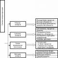
Any car charger circuit consists of the following components:
- Power unit.
- Current stabilizer.
- Charge current regulator. Can be manual or automatic.
- Indicator of current level and (or) charge voltage.
- Optional - charge control with automatic shutdown.
Any charger, from the simplest to an intelligent machine, consists of the listed elements or a combination thereof.
Simple diagram for a car battery
Normal charge formula as simple as 5 kopecks - the basic battery capacity divided by 10. The charging voltage should be a little more than 14 volts (we are talking about a standard 12 volt starter battery).
Analysis of more than 11 circuits for making a charger with your own hands at home, new circuits for 2017 and 2018, how to assemble a circuit diagram in an hour.
TEST:
To understand whether you have the necessary information about batteries and chargers for them, you should take a short test:- What are the main reasons why a car battery discharges on the road?
A) The motorist got out of the vehicle and forgot to turn off the headlights.
B) The battery has become too hot due to exposure to sunlight.
- Can the battery fail if the car is not used for a long time (sitting in a garage without starting)?
A) If left idle for a long time, the battery will fail.
B) No, the battery will not deteriorate, it will only need to be charged and it will function again.
- What current source is used to recharge the battery?
A) There is only one option - a network with a voltage of 220 volts.
B) 180 Volt network.
- Is it necessary to remove the battery when connecting a homemade device?
A) It is advisable to remove the battery from its installed location, otherwise there is a risk of damaging the electronics due to high voltage.
B) It is not necessary to remove the battery from its installed location.
- If you confuse “minus” and “plus” when connecting a charger, will the battery fail?
A) Yes, if connected incorrectly, the equipment will burn out.
B) The charger simply will not turn on; you will need to move the necessary contacts to the correct places.
Answers:
- A) Headlights not turned off when stopping and sub-zero temperatures are the most common causes of battery discharge on the road.
- A) The battery fails if it is not recharged for a long time when the car is idle.
- A) For recharging, a mains voltage of 220 V is used.
- A) It is not advisable to charge the battery with a homemade device if it is not removed from the car.
- A) The terminals should not be mixed up, otherwise the homemade device will burn out.
Battery on vehicles require periodic charging. The reasons for the discharge can be different - from headlights that the owner forgot to turn off, to negative temperatures outside in winter. For recharge battery You will need a good charger. This device is available in large varieties in auto parts stores. But if there is no opportunity or desire to purchase, then memory You can do it yourself at home. There are also a large number of schemes - it is advisable to study them all in order to choose the most suitable option.
Definition: The car charger is designed to transfer electric current with a given voltage directly to Battery
Answers to 5 Frequently Asked Questions
- Will I need to take any additional measures before charging the battery in my car?– Yes, you will need to clean the terminals, since acid deposits appear on them during operation. Contacts It needs to be cleaned very well so that current flows to the battery without difficulty. Sometimes motorists use grease to treat terminals; this should also be removed.
- How to wipe charger terminals?— You can buy a specialized product in a store or prepare it yourself. Water and soda are used as a self-made solution. The components are mixed and stirred. This is an excellent option for treating all surfaces. When the acid comes into contact with soda, a reaction will occur and the motorist will definitely notice it. This area will need to be thoroughly wiped to get rid of all acids. If the terminals were previously treated with grease, it can be removed with any clean rag.
- If there are covers on the battery, do they need to be opened before charging?— If there are covers on the body, they must be removed.
- Why is it necessary to unscrew the battery caps?— This is necessary so that the gases formed during the charging process can freely exit the case.
- Is there a need to pay attention to the electrolyte level in the battery?- This is done without fail. If the level is lower than required, then you need to add distilled water inside the battery. Determining the level is not difficult - the plates must be completely covered with liquid.
It’s also important to know: 3 nuances about operation
The homemade product differs somewhat in its method of operation from the factory version. This is explained by the fact that the purchased unit has built-in functions, helping in work. They are difficult to install on a device assembled at home, and therefore you will have to adhere to several rules when operation.
- A self-assembled charger will not turn off when the battery is fully charged. That is why it is necessary to periodically monitor the equipment and connect it to multimeter– for charge control.
- You need to be very careful not to confuse “plus” and “minus”, otherwise Charger will burn.
- The equipment must be turned off when connecting to charger.
By following these simple rules, you will be able to recharge correctly battery and avoid unpleasant consequences.
Top 3 charger manufacturers
If you don’t have the desire or ability to assemble it yourself memory, then pay attention to the following manufacturers:
- Stack.
- Sonar.
- Hyundai.
How to avoid 2 mistakes when charging a battery
It is necessary to follow the basic rules in order to properly nourish battery by car.
- Direct to mains battery connection is prohibited. Chargers are intended for this purpose.
- Even device made with high quality and good materials, you will still need to periodically monitor the process charging, so that troubles don't happen.
Following simple rules will ensure reliable operation of self-made equipment. It is much easier to monitor the unit than to spend money on components for repairs.
The simplest battery charger
Scheme of a 100% working 12 volt charger
Look at the picture for the diagram memory at 12 V. The equipment is intended for charging car batteries with a voltage of 14.5 Volts. The maximum current received during charging is 6 A. But the device is also suitable for other batteries - lithium-ion, since the voltage and output current can be adjusted. All the main components for assembling the device can be found on the Aliexpress website.
Required components:
- dc-dc buck converter.
- Ammeter.
- Diode bridge KVRS 5010.
- Hubs 2200 uF at 50 volts.
- transformer TS 180-2.
- Circuit breakers.
- Plug for connecting to the network.
- "Crocodiles" for connecting terminals.
- Radiator for diode bridge.
Transformer any one can be used at your own discretion. The main thing is that its power is not lower than 150 W (with a charging current of 6 A). It is necessary to install thick and short wires on the equipment. The diode bridge is fixed on a large radiator.

Look at the picture of the charger circuit Dawn 2. It is compiled according to the original Memory If you master this scheme, you will be able to independently create a high-quality copy that is no different from the original sample. Structurally, the device is a separate unit, closed with a housing to protect the electronics from moisture and exposure to bad weather conditions. It is necessary to connect a transformer and thyristors on the radiators to the base of the case. You will need a board that will stabilize the current charge and control the thyristors and terminals.
1 smart memory circuit

Look at the picture for a circuit diagram of a smart charger. The device is necessary for connection to lead-acid batteries with a capacity of 45 amperes per hour or more. This type of device is connected not only to batteries that are used daily, but also to those on duty or in reserve. This is a fairly budget version of the equipment. It does not provide indicator, and you can buy the cheapest microcontroller.
If you have the necessary experience, then you can assemble the transformer yourself. There is also no need to install audible warning signals - if battery connects incorrectly, the discharge lamp will light up to indicate an error. The equipment must be supplied pulse block power supply 12 volts - 10 amperes.
1 industrial memory circuit

Look at the industrial diagram charger from Bars 8A equipment. Transformers are used with one 16-volt power winding, several vd-7 and vd-8 diodes are added. This is necessary in order to provide a bridge rectifier circuit from one winding.
1 inverter device diagram

Look at the picture for a diagram of an inverter charger. This device discharges the battery to 10.5 Volts before charging. The current is used with a value of C/20: “C” indicates the capacity of the installed battery. After that process the voltage rises to 14.5 Volts using a discharge-charge cycle. The ratio of charge and discharge is ten to one.
1 electrical circuit charger electronics

1 powerful memory circuit

Look at the picture at the diagram of a powerful charger for a car battery. The device is used for acidic battery, having high capacity. The device easily charges a car battery with a capacity of 120 A. The output voltage of the device is self-regulated. It ranges from 0 to 24 volts. Scheme It is notable for the fact that it has few components installed, but it does not require additional settings during operation.

Many could already see the Soviet Charger. It looks like a small metal box and may seem quite unreliable. But this is not true at all. The main difference between the Soviet model and modern models is reliability. The equipment has structural capacity. In the event that to the old device connect the electronic controller, then charger it will be possible to revive. But if you no longer have one at hand, but there is a desire to assemble it, you need to study the diagram.
To the features their equipment includes a powerful transformer and rectifier, with the help of which it is possible to quickly charge even a very discharged battery. Many modern devices will not be able to reproduce this effect.
Electron 3M

In an hour: 2 DIY charging concepts
Simple circuits
1 the simplest scheme for an automatic charger for a car battery

Thyristor car chargers are very popular among homemade car enthusiasts, in which power from a powerful transformer is supplied to the battery through a thyristor controlled by the pulses that open it from the generator. In its simplest form, the diagram will look like this:

And there is nothing to smile about - it really works and at one time was successfully used for quite a long time. A more complex version, with a separate pulse generator and control of charge modes (battery voltage) is shown in the following circuit diagram:

But if experience allows, it would be better to assemble a third automatic charging thyristor, which, in addition to being assembled by many people, has quite good parameters and capabilities.
Schematic and printed circuit board of the SCR memory


The printed circuit board is drawn by hand with a marker. You can make the wiring yourself, for example based on this picture:

Charger parameters
- Output voltage 1 - 15 V
- Current limit up to 8 A
- Battery overcharge protection.
- Accidental output short circuit protection
- Protection against polarity reversal
Functional description of the circuit
The alternating voltage from the secondary winding of the transformer (about 17 V) is supplied to the controlled thyristor-diode bridge, then, depending on the control pulses coming from the controller, it is supplied to the battery terminals.
The controller consists of a separate mains transformer, its voltage is generated by the LM7812 stabilizer, the CD4538 double multivibrator makes control pulses on the thyristors, and has battery voltage control circuits consisting of a CNY17 optocoupler and a TL431 reference voltage source operating as a comparator.
If the voltage at the output of TL431 (R) is below 2.5V (divider system with PR2 with resistors), current does not flow through TL431 through LED2 and CNY17 due to blocking of transistor BC238, which leads to a high state at the reset input pin 13 of the chip CD4538 and its normal operation (if control pulses are sent to the gates of the thyristor), if the voltage increases (as a result of charging the battery), then TL431 begins to act, the current stops flowing through LED2 and CNY17, BC238 is triggered and the low state is applied to pin 13, generation control pulses on the thyristor gate stop and the voltage on the battery is turned off. The cut-off voltage is set by PR4 at 14.4 V. LED1 becomes more and more frequent during charging and is almost at the final stage.
We also used 2 80 C temperature sensors. One is glued to the radiator, and the other is glued to the secondary winding of the network transformer, the sensors are connected in series. Activation of the sensor leads to switching off the voltage on the optocoupler and blocking the CD4538 multivibrator and the absence of thyristor gate control signals.
The fan is permanently connected to the battery.
The circuit has the AUT/MAN switch in the MAN position, and the automatic battery voltage control system is disabled and the battery can be charged manually by monitoring the voltage.
Here are several options for connecting rectifiers and thyristors:

- Scheme in Fig. A. The least favorable switching on, high voltage drop and strong heating of the bridge plus losses on the thyristor. Advantages: One heatsink can be used because the rectifier bridges are usually isolated from the case.
- Scheme in Fig. B most beneficial, losses only on thyristors. But two radiators.
- Scheme in Fig. WITH moderately profitable. Three or one radiator (with one radiator, one double Schottky diode or two diodes with a cathode on the body.
These are the normal voltages at the pins of the CD4538 chip:
1 - 0 V
2 - from 11.5 V to 6 V when turning potentiometer P
3.16 - 12 V
4,6,11 - from 2 V to 12 V when turning P
5 - approximately 10 V
10.12 - about 0.1 V
13 - about 11.5 V with LED1 off
14 - about 12 V
15 — 0
The BD135 collector has about 19.9 V. For more detailed settings, you will need an oscilloscope. The circuit is quite simple and, if assembled correctly, should start immediately after voltage is applied.
Photo of the charging manufacturing process


The diode-thyristor bridge is placed on separate boards and can conduct current up to 20 A, the radiators are isolated from each other and the housing. The secondary winding of the transformer is wound with wire with a diameter of about 2 mm, and with forced cooling it can provide a long-term output of about 8 A (enough for most car enthusiasts' needs, charging batteries up to 82 A/h). But nothing prevents you from installing a transformer with even greater power.


Here, separate measuring wires are used, which are connected to the current terminals.


Charging the battery: the charging current is 1/10 of the battery capacity, after a while, depending on the degree of discharge, LED1 begins to blink and soon approaches a voltage of 14.4 V. Most often, the charging current also drops, at the end of charging the diode lights up almost all the time. A small hysteresis is introduced by an electrolytic capacitor at the R pin of TL431.
The cost of assembling a homemade charger is determined by the main transformer (160 W, 24 V) approximately 1000 rubles, as well as powerful diodes and thyristors. Usually there is enough of this stuff in amateur radio stores (as well as ready-made cases for something), so ideally it won’t cost a penny.
A device with electronic control of the charging current, made on the basis of a thyristor phase-pulse power regulator.It does not contain scarce parts; if the parts are known to work, it does not require adjustment.
The charger allows you to charge the car rechargeable batteries current from 0 to 10 A, and can also serve as an adjustable power source for a powerful low-voltage soldering iron, vulcanizer, portable lamp.
The charging current is similar in shape to pulse current, which is believed to help extend battery life.
The device is operational at temperatures environment from - 35 °C to + 35 °C.
The device diagram is shown in Fig. 2.60.
The charger is thyristor regulator power with phase-pulse control, powered from the winding II step-down transformer T1 through a diode moctVDI + VD4.
The thyristor control unit is made on an analogue of a unijunction transistor VTI, VT2. The time during which capacitor C2 charges before switching the unijunction transistor can be adjusted with a variable resistor R1. When the engine is in the extreme right position according to the diagram, the charging current will become maximum, and vice versa.
Diode VD5 protects the thyristor control circuit VS1 from the reverse voltage that appears when the thyristor is turned on.
The charger can later be supplemented with various automatic components (switching off upon completion of charging, maintaining normal battery voltage during long-term storage, signaling the correct polarity of the battery connection, protection against output short circuits, etc.).
The shortcomings of the device include fluctuations in the charging current when the voltage of the electric lighting network is unstable.
Like all similar thyristor phase-pulse regulators, the device interferes with radio reception. To combat them, it is necessary to provide a network LC- a filter similar to that used in switching power supplies.
Capacitor C2 - K73-11, with a capacity of 0.47 to 1 μF, or K73-16, K73-17, K42U-2, MBGP.
We will replace the KT361A transistor with KT361B - KT361Ё, KT3107L, KT502V, KT502G, KT501Zh - KT50IK, and KT315L - to KT315B + KT315D KT312B, KT3102L, KT503V + KT503G, P307. Instead of KD105B, diodes KD105V, KD105G or D226 with any letter index are suitable.
Variable resistor R1- SP-1, SPZ-30a or SPO-1.
Ammeter PA1 - any direct current with a scale of 10 A. You can make it yourself from any milliammeter by choosing a shunt based on a standard ammeter.
fuse F1 - fusible, but it is convenient to use a 10 A network circuit breaker or an automobile bimetallic circuit breaker for the same current.
Diodes VD1 + VP4 can be any for a forward current of 10 A and a reverse voltage of at least 50 V (series D242, D243, D245, KD203, KD210, KD213).
The rectifier diodes and thyristor are placed on heat sinks, each with a useful area of about 100 cm*. To improve the thermal contact of devices with heat sinks, it is better to use thermally conductive pastes.
Instead of the KU202V thyristor, KU202G - KU202E are suitable; It has been verified in practice that the device operates normally even with more powerful thyristors T-160, T-250.
It should be noted that it is possible to use the iron casing wall directly as a heat sink for the thyristor. Then, however, there will be a negative terminal of the device on the case, which is generally undesirable due to the threat of accidental short circuits of the positive output wire to the case. If you strengthen the thyristor through a mica gasket, there will be no risk of a short circuit, but the heat transfer from it will worsen.
The device can use a ready-made network step-down transformer of the required power with a secondary winding voltage of 18 to 22 V.
If the transformer has a voltage on the secondary winding of more than 18 V, the resistor R5 should be replaced with another one of the highest resistance (for example, at 24 * 26 V, the resistance of the resistor should be increased to 200 Ohms).
In the case when the secondary winding of the transformer has a tap from the middle, or there are two identical windings and the voltage of each is within the specified limits, then it is better to design the rectifier according to the usual full-wave circuit with 2 diodes.
With a secondary winding voltage of 28 * 36 V, you can completely abandon the rectifier - its role will simultaneously be played by a thyristor VS1 ( rectification - half-wave). For this version of the power supply you need a resistor between R5 and use the positive wire to connect a separating diode KD105B or D226 with any letter index (cathode to resistor R5). The choice of thyristor in such a circuit will be limited - only those that allow operation under reverse voltage are suitable (for example, KU202E).
For the described device, a unified transformer TN-61 is suitable. Its 3 secondary windings must be connected in series, and they are capable of delivering current up to 8 A.
All parts of the device, except transformer T1, diodes VD1 + VD4 rectifier, variable resistor R1, fuse FU1 and thyristor VS1, mounted on a printed circuit board made of foil fiberglass laminate 1.5 mm thick.
The board drawing is presented in radio magazine No. 11 for 2001.