There are three thread systems used in mechanical engineering: metric, inch and pipe.
Metric thread(Fig. 145, a) has a triangular profile with an apex of 60°.
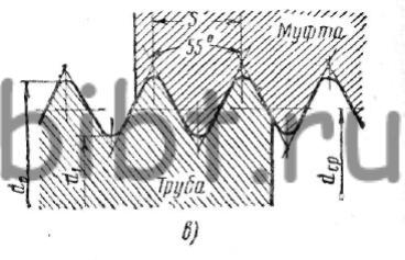
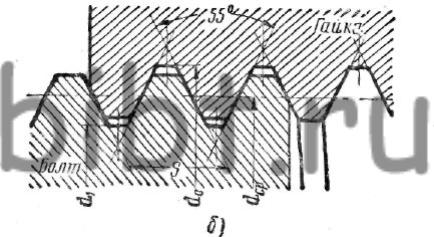
Rice. 145. Thread systems: a - metric, b - inch, c - pipe
There are six types of metric threads: main and minor -1; 2; 3; 4th and 5th. Small threads differ in pitch size for a given diameter, expressed in millimeters. Metric threads are designated by the letter M and numbers characterizing the dimensions of the outer diameter and pitch. For example, M42X4.5 denotes a metric main one with an outer diameter of 42 mm and a pitch of 4.5 mm.
Fine threads, in addition, have a number in the designation indicating the thread number, for example 2M20X1.75 - the second metric fine, outer diameter 20 mm, pitch 1.75 mm.
Inch thread(Fig. 145, b) has an angle of 55° at the apex. Inch threads are cut in the manufacture of spare parts for machines with inch threads and should not be cut on new products. An inch thread is characterized by the number of threads per inch (1") length. The outer diameter of an inch thread is measured in inches.
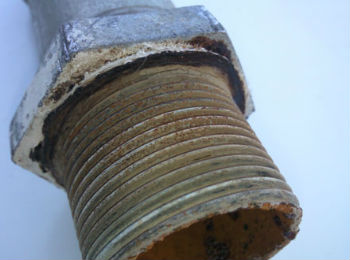
Pipe thread(Fig. 145, c) is measured in the same way as the inch thread, in inches and is characterized by the number of threads per 1". The thread profile has an angle of 55°. For pipe threads, the diameter is conventionally taken to be the diameter of the pipe hole, on outer surface which the thread is cut.
The tops of the protrusions of screws and nuts with pipe threads are made with flat or rounded cuts.
The flat-cut profile is easier to manufacture and is used for threads of conventional pipe connections. Pipe thread is designated: 1/4" PIPE; 1/2" PIPE. etc. (Table 25).
Table 25 Designation of threads in drawings
| Thread type | Legend | Notation elements | An example of a bolt and nut thread designation |
Metric basic |
M | Thread outer diameter (mm) or outer diameter and pitch (mm) | M64 or M64X6 or 64x6 |
Metric small |
1M | 1M 64X4 or 64X4 | |
| 2M | 2M 64X3 or 64X3 | ||
| 3m | 3M 64X2 or 64X2 | ||
| 4M | 4M 64X1.5 or 64X1.5 | ||
| 5M | 5M 64X1 or 64X1 | ||
Trapezoidal |
LADDER | Outer diameter and thread pitch (mm) | LADDER. 22x5 |
| UP | UP 70X10 | ||
Inch with a profile angle of 55° |
Nominal thread diameter in inches | 1" | |
Pipe cylindrical |
TUBE PR* PIPE KR** | Symbol threads in inches | 3/4" TUBE OL 3/4" TUBE KR |
Pipe conical |
TUBE CONIC. | 3/4" TUBE |
* Profile with flat-cut tops (straight). ** The profile is rounded.
Threads can be right-handed or left-handed; by the number of passes - one-, two-, three-pass and multi-pass.
In order to determine the number of thread starts, it is enough to look at the end of the screw or nut and count how many thread ends there are on it.
As a rule, all fasteners (bolts, screws, screws, etc.) have single-start threads.
In this article, I want not only to provide dry facts about the sizes of inch pipe threads with references to standards and GOSTs, but to bring to the reader an interesting fact about the features of the designation of the latter.
So, those who have already encountered pipe threads have been more than once surprised at the discrepancy between the outer diameter of the thread and its designation. For example, a 1/2-inch thread has an outer diameter of 20.95 mm, although logically with metric threads it should be 12.7 mm. The thing is that inch threads actually indicate the through hole of the pipe, and not the outer diameter of the thread. At the same time, by adding to the size of the hole in the pipe wall, we get the overestimated outer diameter that we are accustomed to in the designation of metric threads. Conventionally, the so-called pipe inch is 33.249 mm, that is, 25.4 + 3.92+ 3.92 (where 25.4 is the passage, 3.92 is the pipe wall). The pipe walls are taken based on the working pressure for the thread. Depending on the diameter, the pipes also increase accordingly, since a pipe with a larger diameter must have thicker walls than a pipe with a smaller diameter for the same operating pressure.
Pipe threads are divided into the following:
Cylindrical pipe thread
This is an inch thread based on BSW (British Standard Whitworth) thread and corresponds to BSP (British standard pipe thread) thread, has four pitch values of 28,19,14,11 threads per inch. Cuts on pipes up to size 6", pipes over 6" are welded.
The profile angle at the apex is 55°, the theoretical profile height is Н=0.960491Р.
Standards:
GOST 6357-81 - Basic standards of interchangeability.
Cylindrical pipe thread. ISO R228, EN 10226, DIN 259, BS 2779, JIS B 0202.
Symbol: letter G, numerical value of the nominal diameter of the pipe in inches (inch), accuracy class of the average diameter (A, B), and letters LH for left-hand threads. For example, a thread with a nominal diameter of 1 1/4", accuracy class A is designated as G1 1/4-A. Once again, we would like to remind you that it should be borne in mind that the nominal thread size corresponds to the clearance of the pipe in inches. The outer diameter of the pipe is in some proportion with this size and more accordingly to the thickness of the pipe walls.
Designation of cylindrical pipe thread size (G), steps and nominal values of outer, middle and inner thread diameters, mm
| Thread size designation | Step P | Thread diameters | |||
|---|---|---|---|---|---|
| Row 1 | Row 2 | d=D | d 2 =D 2 | d 1 =D 1 | |
| 1/16" | 0,907 | 7,723 | 7,142 | 6,561 | |
| 1/8" | 9,728 | 9,147 | 8,566 | ||
| 1/4" | 1,337 | 13,157 | 12,301 | 11,445 | |
| 3/8" | 16,662 | 15,806 | 14,950 | ||
| 1/2" | 1,814 | 20,955 | 19,793 | 18,631 | |
| 5/8" | 22,911 | 21,749 | 20,587 | ||
| 3/4" | 26,441 | 25,279 | 24,117 | ||
| 7/8" | 30,201 | 29.0З9 | 27,877 | ||
| 1" | 2,309 | 33,249 | 31,770 | 30,291 | |
| 1⅛" | 37,897 | 36,418 | 34,939 | ||
| 1¼" | 41,910 | 40,431 | 38,952 | ||
| 1⅜" | 44,323 | 42,844 | 41,365 | ||
| 1½" | 47,803 | 46,324 | 44,845 | ||
| 1¾" | 53,746 | 52,267 | 50,788 | ||
| 2" | 59,614 | 58,135 | 56,656 | ||
| 2¼" | 65,710 | 64,231 | 62,762 | ||
| 2½" | 75,184 | 73,705 | 72,226 | ||
| 2¾" | 81,534 | 80,055 | 78,576 | ||
| 3" | 87,884 | 86,405 | 84,926 | ||
| 3¼" | 93,980 | 92,501 | 91,022 | ||
| 3½" | 100,330 | 98,851 | 97,372 | ||
| 3¾" | 106,680 | 105,201 | 103,722 | ||
| 4" | 113,030 | 111,551 | 110,072 | ||
| 4½" | 125,730 | 124,251 | 122,772 | ||
| 5" | 138,430 | 136,951 | 135,472 | ||
| 5½" | 151,130 | 148,651 | 148,172 | ||
| 6" | 163,830 | 162,351 | 160,872 | ||
In Western technical literature, you will find all measurements in inch metrics. This state of affairs has historical roots. Great Britain was always ahead in terms of technical development, therefore, in all the colonies that it then owned (and there were many of them), this particular measurement system was used. In principle, technicians freely convert inches into sentiment and vice versa. To this day, in these countries, all measurements are made in inches as a standard. Next, we will talk about the main features and characteristics of inch threads and how it differs from metric threads.
Inch thread. Options
If we talk about ordinary measurement, then even in the mind it is not difficult to convert one value into another and vice versa. But as far as carving is concerned, you need to know simple, but important nuances. The fact is that there is great overlap between the metric and imperial metric for measuring lengths. The difference is the number of turns on the threaded pitch. In addition, this carving is distinguished by a different angle of inclination at its apex, which is 55°, if we refer to the Whitworth style. This is considered the norm in England, or, as they also say, the “British corner.” If we take the UNC and UNF standard, which is considered the standard in America, as a basis, then the angle here is 60°.
Metric standard and inch thread. The most fundamental differences
Types of inch threads:
- Outdoor;
- Conical;
- Cylindrical;
- Internal.
1 inch = 25.4 mm. This is the main difference. In documents this has a specific designation - 1´ (with a stroke).
If we talk about American standards, they have a division into threads with a large pitch, which they designate as UNC, and with a fine pitch, UNF. Also, for canonical inch threads the designation is NPT, and for pipe threads - NPSM.
What kind of thread is there and where is it used?
The types of threads used in production, construction and design, depending on the part, are divided into internal, external and conical.
- External is used for bolts, screws, pins and studs.
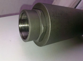
- Internal is used in the manufacture of plugs or nuts. It is cut into holes when you need to organize a connection in a certain place.
- To create a tight connection, as well as locking without additional parts, a conical inch thread is made.
Their designation follows the standard. d (D) is the outer diameter of the bolt or the inner diameter of the nut (d is the diameter of the bolt before threading). The internal diameter of the thread is designated d1 (D1). There is also a designation for the average diameter d2 (D2). This size depends on the nominal pitch, denoted by the letter P.
The letter α is used to indicate the profile angle of the thread. The indicator α = 55° will mean that the angle at the apex of the equilateral triangle of the thread tooth is 55°, and corresponds to the British Standard BSW inch thread. The UTS inch thread, widely used in Canada and the USA, has α = 60°.
Where are inch threads used?
α = 55° -inch thread used in industry for fixing mechanical components and parts using threaded connections. It is especially common in the process of repairing imported equipment and machines, as well as used cars. Metal products with inch threads are also produced in our country. During work, sometimes there is a need to convert metric threads to inch threads and vice versa. This can be done quickly and conveniently using a special reference book.
Threads according to the system of measures are divided into metric and inch. Metric and inch threads are used in threaded connections and screw drives. Threaded connections are detachable connections made using threaded fasteners - bolts, screws, nuts, studs or threads directly applied to the parts being connected.
Metric thread (Fig. 1)
In profile it has the appearance of an equilateral triangle with an apex angle of 60°. The tops of the projections of the mating screw and nut are cut off. A metric thread is characterized by a screw diameter in millimeters and a thread pitch in millimeters. Metric threads are made with large and small pitches. A thread with a large pitch is taken as the main one. Fine threads are used for adjustment and for screwing together thin-walled and dynamically loaded parts. Metric threads with large pitches are designated by the letter M and a number expressing the nominal diameter in millimeters, for example M20. For small metric thread additionally indicate the pitch, for example M20x1.5.
Rice. 1 Metric thread
Inch thread (Fig. 2)
An inch thread (Fig. 2) has the same profile as a metric thread, but its apex angle is 55° (Whitworth thread - British standard BSW (Ww) and BSF), the apex angle is 60° (American standard UNC and UNF). The outer diameter of the thread is measured in inches (1" = 25.4 mm) - dashes (") indicate inches. This thread is characterized by the number of threads per inch. American inch threads are made with coarse (UNC) and fine (UNF) pitch.
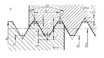
Rice. 2 Inch thread
Fastener size chart for American inch UNC machine threads with coarse pitch (60 degree profile angle)
| Size in inches | Size in mm | Thread pitch/inch |
| UNC No. 1 | 1.854 | 64 |
| UNC No. 2 | 2.184 | 56 |
| UNC No. 3 | 2.515 | 48 |
| UNC No. 4 | 2.845 | 40 |
| UNC No. 5 | 3.175 | 40 |
| UNC No. 6 | 3.505 | 32 |
| UNC No. 8 | 4.166 | 32 |
| UNC No. 10 | 4.826 | 24 |
| UNC No. 12 | 5.486 | 24 |
| UNC 1/4 | 6.35 | 20 |
| UNC 5/16 | 7.938 | 18 |
| UNC 3/8 | 9.525 | 16 |
| UNC 7/16 | 11.11 | 14 |
| UNC 1/2 | 12.7 | 13 |
| UNC 9/16 | 14.29 | 12 |
| UNC 5/8 | 15.88 | 11 |
| UNC 3/4 | 19.05 | 10 |
| UNC 7/8 | 22.23 | 9 |
| UNC 1" | 25.4 | 8 |
| UNC 1 1/8 | 28.58 | 7 |
| UNC 1 1/4 | 31.75 | 7 |
| UNC 1 1/2 | 34.93 | 6 |
| UNC 1 3/8 | 38.1 | 6 |
| UNC 1 3/4 | 44.45 | 5 |
| UNC 2" | 50.8 | 4 1/2 |
Thread
The thread can be internal or external.
- External threads are cut on bolts, studs, screws, pins and various other cylindrical parts;
- Internal threads are cut in fittings, nuts, flanges, plugs, machine parts and metal structures.
Rice. 3 Thread elements
Basic thread elements are presented in Fig. 3 These include the following elements:
- thread pitch- the distance between the tops or bases of two adjacent turns;
- thread depth- the distance from the top of the thread to its base;
- thread angle- the angle between the sides of the profile in the plane of the axis;
- outside diameter- the largest diameter of the bolt thread, measured along the top of the thread perpendicular to the thread axis;
- inner diameter- a distance equal to the diameter of the cylinder on which the thread is screwed.
More about inch fasteners:
Inch threads are used to create turns only in metal pipes. Inch threads are also used in the production of collapsible fittings made of metal and plastic.
Differences between inch and metric threads
Submitted threaded connection has its own standardization based on GOST 6357-81, which regulates thread parameters such as pitch and diameter.
The dimensions of the threaded connections depend on the distance between the oppositely placed upper points located at the end of the pipe.
Pipe thread and its dimensions will directly depend on the value of the internal or external diameter of the product. Currently, the following types of threads are distinguished:
- Metric;
- Inch;
- Trapezoidal;
- Cylindrical;
- Persistent;
- Conical.
Besides, different kinds threads have their own designation. So, for example, the designation of a left-hand type thread is marked with the letters LH. For more detailed information, a threaded connection is indicated in the drawings by additional letters, where:
- M - denotes the nominal diameter of the turns;
- Ph – stroke value;
- P – step value.
Metric threads, like inch threads, have a standard diameter from 1 to 180 mm. Speaking about the differences between these two types, it is worth noting that they lie in the shape of the helical ridge profile.
The inch profile visually looks sharper. This is due to the angle of the upper “original triangle”, which is 55°.
Also, metric pipe threads differ from inch threads in the calculation of pitch and diameter. This is due to the fact that metric turns are created based on millimeters.
A pipe inch is equal to 3.33 cm. In both cases, the pitch parameter of pipe turns is measured not in millimeters, but in threads.
The threads here are the exact number of grooves that are present in a 1-inch section of pipe. So, for example, standard water mains have thread designations in only two variants - 11 threads (metric pitch of 2.31 mm) and 14 threads (metric pitch of 1.8 mm).
Trapezoidal threads are used in the production of all kinds of screws. These include lead screws for cutting machines, screws for hydraulic presses, lifting devices and worm gears.
Such coils are significantly different from other types visually - they are made in the shape of an isosceles trapezoid. The profile angle can be 15, 24, 30 and 40°.
How to determine pitch and diameter?
When determining such significant characteristics, a tool such as:
- Caliber;
- Comb;
- Calipers;
- Micrometer.
In some cases, the caliber function can be performed by a coupling or fitting with pre-applied internal or external turns that correspond to predetermined parameters.
When measuring the pitch, a bolt is used; if significant resistance arises when screwing into the coils, then they are redone.
If the process occurs without difficulty and the bolt is tightly placed in the pipe, the step is considered completed correctly.
When re-creating coils, the process is oriented toward creating a larger caliber. The thread gauge is quite easy to use. It is equipped with measuring plates that are inserted into threaded connections that have not yet been joined.
The plates resemble small files, and if, when applied to the coils, the profile of the plates coincides with the coils cut on the inner or outer surface, then they correspond to the set value.
This value is marked on the tool plate. Using a caliper, only the outer diameter of the coils can be measured; a micrometer also performs the same function. Experts recommend taking measurements with the most suitable tools for this purpose - calibers.
Cutting external pipe threads (video)
Slicing methods
Both metric and pipe (inch) coil analogs can be created on both the internal and external surfaces.
This is done using two methods: mechanical and manual. When implementing the manual method, devices such as swords and dies are used.
The tap can create internal turns, and the die can create external turns. The process begins with the piece being held firmly in a vice and the swordsman inserted into the collar.
When using a die, the die holder performs the vortok function. After this, the die is put on the product, and when using a tap, it is inserted directly into the pipe hole.
If necessary, all actions are repeated again, and turns will gradually be created in the body of the product, at a depth that will be equal to the height of the profile.
Internal and external turns are not cut simultaneously, but in sequential order. However, in most cases, surfaces with only external or internal grooves are created.
Creating turns mechanically involves the use of a special cutter, which is attached to the machine support.
Before starting work, the support moves to the edge of the workpiece, after which the profile height is set using a transverse feed.
At mechanically A die can also be used - a tool with plates having a comb profile.
Using the installed head, you can create 2-5 standard sizes of external type grooves. After the plates are installed in the die head, the pipe is clamped in a vice or using a wrench.
The end of the product is cut at a right angle. After starting the tool, the head creates grooves on the part at the moment of rotation.


