Any modern metropolis and even the smallest settlement cannot do without the use of gas pipelines: both residential buildings and industrial enterprises necessarily use gas - for heating and other household needs. The problem is that such engineering structures are extremely dangerous, even the smallest damage to them is fraught with a big accident and even a catastrophe. That is why gas pipeline protection zones exist.
Definition
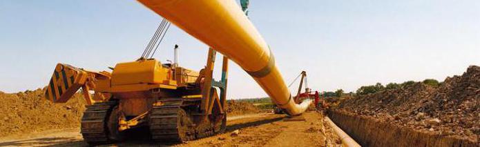
First you need to define the very concept of "gas pipeline". This is an engineering structure consisting of pipes and supports on which they are mounted, as well as a variety of related equipment that helps in delivering gas to the consumer.
Fuel is supplied under a certain pressure, and its transportation is highly dependent on the geographical parameters of the site. Two types of gas pipelines are used: distribution and main - depending on the pressure force. The security zones of gas pipelines also depend entirely on these parameters.
Species and types
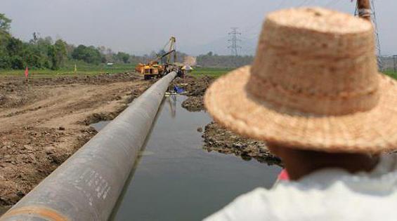
The first type of main gas pipelines has a pressure of up to ten MPa, and the second - up to two and a half MPa. Distribution pipes are of three types: low pressure - up to five thousandths of MPa, medium pressure - up to three tenths of MPa, and high pressure- up to six tenths of MPa. Pipes are laid by underground, above-ground and underwater methods, respectively, hence the name according to this classification. The security zones of gas pipelines also differ depending on the pressure and method of laying.
The main function of protected zones is to prohibit construction in the area. The security zones of gas pipelines are determined by special documents containing the characteristics of the pipes, the method of laying the pipeline and the permissible pressure inside.
The width of the protection zone depends on these characteristics. Thanks to it, the uninterrupted functioning of the facility, safety, integrity and the possibility of maintenance are ensured. Work in the protected zone of the gas pipeline is carried out in coordination with the organization that operates this facility.

Forbidden
It is forbidden to build compost pits, build basements, work with welding, install barriers that prevent access to pipes, create landfills and arbitrarily connect to the gas pipeline in the protected zone.
The security zone of a medium-pressure gas pipeline is usually equipped with special columns with signs on which the following information is given: the name and geographic reference of the object, the distance to the axis of the pipeline, the size of the security zone, and the contact details of the organization that services the object. Such signs can be located on power poles, on cell towers.
Dimensions
The rules for the protection of pipelines provide for the arrangement of protective territories. The security zone of the high-pressure gas pipeline of the distribution gas pipeline is ten meters on both sides of it. The main ones have fifty meters of protected territory. If liquefied gas is delivered through pipes, the security zone is at least one hundred meters. A conventional medium-pressure pipeline requires four meters of such territory, while a low-pressure gas pipeline's protected area is only two meters.
The design and technical documentation without fail contains all the above information and is stored in the design bureau, which most often is the organization for servicing this engineering structure. An act issued by local self-government or executive authorities and the fixation of a buffer zone on the general plan are documents for creating a special territory around the gas pipeline.
Exploitation
The main activities that are carried out in the security zones by the operating organization are as follows: twice a year, the owners of the land where the security zone of the main gas pipeline and any other are instructed on safety; once a year - adjustment of the route with the introduction of all changes in the project documentation, and if the transformation is really necessary, the gas pipeline protection zone itself is also changed. SNiP (building codes and regulations), which regulate all technical, legal and economic regulations, as well as engineering surveys, must be observed.
In connection with the changes discovered during the year, it is necessary to change the marking itself with special columns located at a distance of no more than five hundred meters from each other. In this way, all bends of pipes are indicated, which the security zone of the gas pipeline must also repeat. How many meters from one bend to another - it does not matter, they still need to be fixed without fail. Also, all intersections with other objects belonging to the infrastructure (bridges, roads, etc.) must be marked with signs. A warning that a security zone of a gas pipeline (main or distribution) passes through here is a prerequisite.
Information on the plates
A sign prohibiting parking and even stopping vehicles that are not related to the organization operating the gas pipeline is required. Along with information about the depth (if it is underground) of the gas pipeline, a designation of its direction is given. The first plate stands vertically, the subsequent ones - with the designation of the distance traveled - are placed at an angle of 30 degrees for visual control from the aircraft.
It is necessary to observe all safety measures in such an important area as the gas pipeline security zone (including low pressure). This minimizes the risk and damage of the consequences of accidents. Unauthorized work in the immediate vicinity is unacceptable, since not only a fire, but also an explosion can occur. Liability information is indicated on the plates. The risk of damage to the gas pipeline must also be minimized.
Possible tragic accidents
Few people are insured against harming gas pipelines and other dangerous objects. Any owner of the territory where the security zone is located can damage the insulation or even the pipe itself if, without agreement, they start a large construction site or lay, for example, a water supply system on the site. Damage to pipes is a major administrative violation and provides for a fine of five thousand rubles, depending on the damage caused.
If the protected zones of gas pipelines are well marked on the ground, and preventive work is carried out in a timely manner and carefully, then emergency situations that are associated with this type engineering structures, will not happen, which will help the preservation of material resources, health and even life of people.
Gas supply system
This is a very complex complex, in which facilities are designed not only for transportation, but also for processing and distributing gas to consumers. The system consists of the gas networks themselves, that is, gas pipelines of three types - low, high and medium pressure, as well as gas distribution stations, gas control points and installations, services and auxiliary structures. All this is intended for the normal and uninterrupted operation of the entire gas supply system. It should be safe in operation, simple and easy to maintain, be able to turn off individual sections for repair work or in the event of an accident.
The security zone of the gas pipeline is the main condition for the safe operation of this entire system. Even underwater gas pipeline crossings include a special area, regardless of the category of pipes. It will be equal to one hundred meters on each side of the pipe.
RF rules for protected areas
Gas distribution networks must have security zones of the following order:
- along the route of the external gas pipeline - two meters on each side;
- along the route of the underground gas pipeline ( polyethylene pipes and a copper wire indicating the route) - three meters from the side of the wire and two - from the other side;
- along the route of the external gas pipeline on permafrost (regardless of the material) - ten meters on each side;
- surrounding a detached gas control point - ten meters from the boundary of the facility;
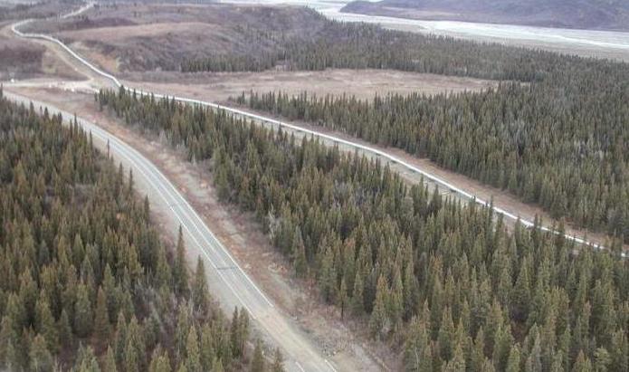
- along the route of the inter-settlement gas pipeline passing through the forest or bushes - a clearing three meters wide on each side.
The low pressure gas pipeline is used for household consumers, small boiler houses, enterprises Catering and other similar purposes. Pipelines with medium or high pressure gas are designed to be connected to city distribution networks through hydraulic distribution stations - gas distribution points. In addition, they are needed to supply gas to industrial enterprises and utilities with the help of GRU (gas control units).
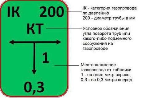
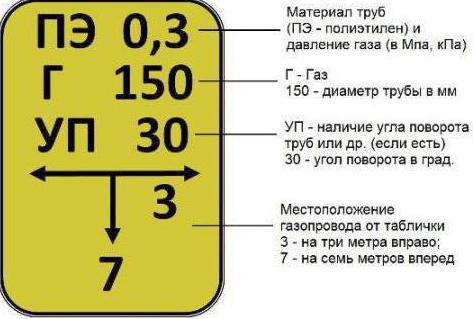
Deciphering pointers
Signposts installed in security zones are green and yellow color, indicating the material from which the pipe is made: yellow - polyethylene, and green - steel. On the yellow plate, the top line is the pressure of this gas pipeline and the material of the pipe. For example, PE 0.6. This means that the pipe is made of polyethylene, and the pressure in it is 0.6 MPa. If the gas pipeline is low pressure, then the letters "n.d." instead of numbers.
The second line indicates the transported medium and the diameter of the pipe itself. For example, GAZ 50. This means that gas is transported through a pipe with a diameter of fifty millimeters. Variation here can only be with numbers, since the diameter of the pipes is varied.
If there is a third line, then it indicates the construction of an underground gas pipeline. For example, UP 20. This means that in this place the angle of rotation is twenty degrees.
The fourth line is the most important, it has arrows and numbers indicating the direction from the axis of the table. For example, the arrow to the right, under which the number 3, and the arrow down, under which the number 7. This means that the gas pipeline is deployed three meters to the right and seven meters forward.
For gas supply from group installations, steel gas pipelines laid underground and designed for a pressure of pure gas of 3-5 kPa, and gas-air mixtures - 1.5-3 kPa.
Underground pipelines. The routing of gas pipelines through the territory of settlements, within quarters or courtyards should ensure the shortest length of gas pipelines and branches from them to residential buildings, as well as the maximum distance from above-ground structures (especially those with basements) and non-pressure underground communications ( sewer pipes, channels for heat pipes and other containers through which gas can spread). The routing of gas pipelines through undeveloped territories should be carried out taking into account the planning of their future development.
In accordance with the requirements of the current "Safety Rules in the Gas Industry" of the Gosgortekhnadzor of the Russian Federation, horizontal distances between low-pressure gas pipelines (up to 5 kPa) and other structures must be clear, m, not less than:
- to the foundation of buildings and structures, overpasses and tunnels - 2;
- poles for outdoor lighting, contact network and communications - 1;
- axes of the extreme track of the railway gauge 1520 mm - 3.8;
- axes of the extreme track of the tram - 2.8;
- side stone of the street, road - 1.5;
- the outer edge of the ditch or to the sole of the embankment of the street, road - 1;
- foundations of supports of overhead power lines with voltage up to 1 kV and outdoor lighting - 1, over 1 to 35 kV - 5, and above - 6;
- tree trunks - 1.5;
- shrubs - not standardized.
When laying gas pipelines between buildings and under the arches of buildings, as well as in certain sections of the route where the given distances cannot be maintained, it is allowed to reduce them to values that ensure the safety of all underground structures during the construction and repair of each of them. If it is necessary to reduce the distance, long seamless pipes with increased wall thickness are used; bent bends are used; welded joints are checked by physical control methods; pipes are protected from corrosion by highly reinforced insulation.
The minimum distances in the plan between engineering underground networks horizontally in the light must be, m, not less than:
- to the water supply - 1;
- household sewerage - 1;
- drainage and rain sewerage - 1;
- gas pipelines of low, medium, high pressure - 0.5;
- power cables up to 100 kV and communication cables - 1;
- heat networks and common collectors - 2.
Laying of two or more gas pipelines in one trench is allowed at the same or different levels (steps). The distances between gas pipelines must be sufficient for the installation and repair of pipelines, but not less than 0.4 m for pipes with a diameter of up to 300 mm.
Clear vertical distances at the intersection of underground gas pipelines of all pressures with other underground structures and communications should be, m, not less than:
- plumbing, sewerage, drainage, telephone sewerage, etc. - 0.15;
- heating network channel - 0.2;
- electric cable, telephone armored cable - 0.5;
- oil-filled electric cable (110–220 kV) - 1.
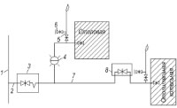
Rice. 5.2. Scheme of gas supply to an industrial enterprise from urban medium-pressure gas pipelines. 1 - urban distribution gas pipeline of medium (or high) pressure; 2 - input of the gas pipeline; 3 - valve with a compensator in a deep well; 4 - underground intershop gas pipelines of medium or high pressure; 5 - hydraulic fracturing and the central point for measuring gas flow; 6 - underground intershop gas pipelines of medium pressure; 7 - crane; 8 - elevated gas pipelines laid along the wall of the building; 9 - cabinet GRU (SHRU); 10 - valve with a compensator in a deep well (shutdown device of the workshop); 11 - fitting with a tap and a stopper for sampling; 12 - purge gas pipeline; 13 - disconnecting device (valve) at the entrance to the workshop; 14 - tap in a shallow well; 15 - elevated intershop gas pipelines laid along columns; 16 - U-shaped compensator; 17 - a valve on an aboveground gas pipeline with a platform and a ladder for its maintenance; 18 - intrashop GRU.
Reducing the distance between the gas pipeline and the electric cable or armored communication cable is possible if they are laid in cases, while the clear distance between the gas pipeline and the wall of the case should be, m, not less than: when laying the electric cable - 0.25; armored communication cable - 0.15, and the ends of the case should extend 1 m in both directions from the walls of the crossed gas pipeline.
Above ground pipelines. These gas pipelines are more accessible to the supervision of maintenance personnel, are less susceptible to deformations, and allow you to quickly eliminate possible problems and perform repairs without disconnecting consumers. It is allowed to lay low and medium pressure gas pipelines along the outer walls of residential and public buildings not lower than the IV degree of fire resistance and free-standing fireproof supports, and low pressure gas pipelines with a nominal pipe diameter of up to 50 mm - along the walls of residential buildings.
Aboveground gas pipelines should be designed taking into account the compensation of longitudinal deformations and, if necessary, when self-compensation is not provided, the installation of compensators (not stuffing boxes) should be provided. The height of the gas pipeline laying should be selected taking into account the provision of its inspection and repair. Under window openings and balconies of buildings, flanged or threaded connections on gas pipelines. Gas pipelines laid along the outer walls of buildings, overpasses, supports, as well as risers at the exit from the ground, if necessary, must be protected from mechanical damage. Gas pipelines must have a slope of at least 0.003, at the lowest points it is necessary to install devices for removing condensate. Thermal insulation should be provided for these gas pipelines.
The minimum horizontal clear distances from above-ground gas pipelines laid on supports to residential and public buildings must be at least 2 m. pipeline diameter, but not less than 100 mm. The distances between the supports of aboveground gas pipelines should be determined in accordance with the requirements of the current "Instructions for the calculation steel pipes wires for various purposes.
Shutdown devices. Gas pipelines provide for the installation of disconnecting devices at the gas pipeline inlets to individual buildings or their groups (two adjacent buildings or more), as well as in front of outdoor (open) gas-consuming installations. On underground gas pipelines, they should be installed in shallow wells with compensators. On gas pipelines with a nominal bore of less than 100 mm, U-shaped compensators should be used predominantly. With steel fittings attached to gas pipelines by welding, compensators are not installed.
The installation of shut-off devices at the inlets of low-pressure gas pipelines should, as a rule, be provided outside the building. For fittings located at a height of more than 2.2 m, platforms made of non-combustible materials with ladders or a remote drive should be provided. For the maintenance of rarely used fittings, it is allowed to provide for the use of a portable ladder.
When laying two or more gas pipelines in one trench, the installed shutoff valves must be displaced relative to each other by a distance that ensures ease of maintenance and repair.
Gas pipelines indoors. Inside the premises, gas pipelines are laid openly along the walls, parallel to the floor (ceiling). The length of LPG pipelines from risers to gas appliances is minimal. Pipes are not allowed to cross living rooms, and when passing through walls - smoke and ventilation ducts. When attaching gas pipelines to the walls, it is necessary to observe distances that provide the possibility of inspecting and repairing gas pipelines and the equipment installed on them. stop valves. Installation of taps with a stop nut towards the wall is unacceptable.
The mutual arrangement of gas pipelines and electrical wiring inside buildings must meet the following requirements:
- from an openly laid electrical wire (electrical wire) to the gas pipeline wall, a distance of at least 10 cm must be maintained (it can be reduced to 5 cm when laying electrical wires in tubes);
- at the intersection of the gas pipeline with an openly laid electric wire, the latter must be enclosed in a rubber or ebonite tube protruding 10 cm from each side of the gas pipeline;
- with a hidden electrical wire, a distance of at least 5 cm must be maintained from the wall of the gas pipeline, counting to the edge of the sealed furrow.
At the intersection of the gas pipeline with other pipelines (water supply, sewerage), their pipes should not touch. To turn off the gas, in addition to the tap, on each riser, taps are installed at the entrance to the apartment, in the stairwell (at the stair riser), on the branch from the riser to the appliances in the kitchen and in front of each appliance. If the riser is located in the kitchen and only one gas appliance (stove without a meter) is installed in the apartment, the shut-off valve at the outlet from the riser can not be installed. Gas pipelines laid indoors must be made of steel pipes. The connection of pipes should be provided, as a rule, by welding. Threaded and flange connections are allowed only in places where shutoff valves and gas appliances are installed. Detachable connections of gas pipelines must be accessible for inspection and repair.
The laying of gas pipelines inside buildings and structures should be provided open. In the premises of consumer services enterprises, public catering and laboratories, it is allowed to lay gas pipelines to individual units, gas appliances in a concrete floor, followed by sealing the pipes with cement mortar. At the same time, anti-corrosion insulation must be provided for the pipes. In places where the gas pipeline enters the floor and exits from it, cases should be provided that protrude above them by at least 3 cm.
Fundamentally, the arrangement of gas pipelines for supplying industrial and municipal enterprises with increased gas consumption is distinguished by the possibility of using medium pressure. According to the "Safety Rules in the Gas Industry" and SNiP 42-01-02, intershop gas pipelines at industrial enterprises can be both underground and aboveground. The choice of the method of laying inter-shop gas pipelines depends on the degree of saturation of the territory with underground utilities, the type of soil and coatings, the nature of building structures and buildings, the location of shops that consume gas, and technical and economic considerations. As a rule, enterprises prefer overhead laying intershop gas pipelines.
Gas supply schemes for enterprises, as well as methods for laying gas pipelines, are diverse. When choosing a scheme, it is necessary to be guided by technical and economic requirements, as well as the requirements of reliability and safety: ensuring the necessary parameters of combustible gas (pressure and flow rate) before gas burners heat units; minimum capital and metal investments (minimum diameters and lengths of gas pipelines, the number of hydraulic fracturing and gas distribution units); ensuring reliable and safe construction, installation and commissioning, operation.
Depending on the gas flow and pressure, the mode of operation of heat units, the territorial location of gas consumers at the enterprise and technical and economic indicators, and taking into account design and operation practices, several typical gas supply schemes for industrial and municipal enterprises are distinguished.
Municipal enterprises with a relatively low gas consumption and heat units operating on low-pressure gas (kitchen factories, canteens, built-in heating boilers with sectional boilers, etc.), as a rule, are connected to low-pressure city gas pipelines or tank farms (for complexes autonomous gas supply with propane-butane mixtures) (Fig. 5.1).
The gas supply scheme consists of a gas pipeline input with a common shut-off device, intershop gas pipelines with shut-off devices in front of each shop, purge gas pipelines and such elements as control tubes, control conductors, condensate collectors (for wet gases), compensators, etc.
A common disconnecting device (valve) is installed at the inlet of the gas pipeline. It is designed to turn off the gas supply during repairs or accidents in the gas supply system. Purge gas pipelines are designed to remove air and gas-air mixture and fill the system with clean gas during the initial and subsequent (after repairs of inter-shop gas pipelines or a long shutdown of the system) starts. To determine the quality of the purge, a fitting with a valve is installed on the purge gas pipeline for sampling the medium, the composition of which can be determined on the gas analyzer.
In the gas supply scheme under consideration, it is conventionally accepted underground laying gas pipelines. The diagram does not show condensate collectors: dry natural gas is used for centralized gas supply, and when using wet combustible gases, gas pipelines are laid with a slope and condensate collectors are installed at low points of the system.
Medium and large industrial enterprises are connected to the city distribution pipelines of medium or high pressure (Fig. 5.2). As an example, it is assumed that in shops 2 and 3, the heat units operate on medium pressure gas (the gas pressure in front of the burners of the units is assumed to be equal), and in shops 1 and 4 - on low pressure gas. After the common shut-off device on the intershop gas pipeline of the initial gas pressure, a gas control point (GRP) is installed, designed to reduce the gas pressure from high or medium to medium pressure, necessary for the heat units of shops 2 and 3, taking into account pressure losses. A central point for measuring gas flow was installed in the hydraulic fracturing building, designed for economic settlements between the enterprise and the supplier. In shops 1 and 4, a gas control unit (GRU) was additionally installed to use low-pressure gas.
For intershop gas pipelines, a mixed laying scheme has been adopted - underground and aboveground. Aboveground gas pipelines can be laid along the outer walls and fireproof coatings of industrial buildings with industries classified by fire hazard to categories C, D and D, as well as along freestanding columns (supports) and overpasses made of fireproof materials. Important note: high-pressure gas pipelines can be laid along the walls of industrial buildings only above the windows of the upper floors or along blank walls.
Diameters of gas pipelines are determined hydraulic calculation at the maximum gas consumption, taking into account the prospective growth in consumption associated with the development of the enterprise, and allowable pressure losses. All underground steel gas pipelines are protected from corrosion caused by soil and stray electric currents. For this, both passive and active protection measures are applied.
The features of autonomous gas supply systems using low and medium pressures include the predominant use of burners with forced air supply, optimized for operation on low pressure gas. In this case, there is no need to reduce the pressure, as it is necessary to do when supplying from centralized highways. natural gas(pressure reduction in regulators reaches 0.1–0.2 MPa).
Table 5.5. Gas pressure in supply lines for different consumers
| Gas consumers | Gas pressure, MPa |
| Industrial buildings in which the magnitude of the gas pressure is determined by the requirements of production | 1,2 |
| Other industrial buildings | 0,6 |
| Household buildings of industrial enterprises, detached, attached to industrial buildings and built into these buildings | 0,3 |
| Administrative buildings | 0,005 |
| Boiler houses | |
| stand-alone on the territory of industrial enterprises | 1,2 |
| stand-alone in the territory of settlements | 0,6 |
| attached, built-in and roof industrial buildings | 0,6 |
| attached, built-in and roof public, administrative and domestic buildings | 0,3 |
| attached, built-in and roof residential buildings | 0,005 |
| Public buildings (except buildings in which the installation gas equipment requirements of SNiP 2.08.02 is not allowed) and warehouse | 0,005 |
| residential buildings | 0,003 |
Table 5.6. Gas pressure in aboveground gas pipelines depending on the class of consumers and location features
| Placement of elevated gas pipelines | Gas pressure in the gas pipeline, MPa, no more |
| 1. On free-standing supports, columns, flyovers and whatnots | 1.2 (for natural gas); 1.6 (for LPG) |
| 2. Boiler rooms, industrial buildings with premises of categories C, D and D and buildings of the STS (SNP), public and domestic buildings for industrial purposes, as well as built-in, attached and roof boiler rooms to them: | |
| a) on the walls and roofs of buildings | |
| I and II degrees of fire resistance of fire hazard class C0 (according to SNiP 21-01) | 1,2* |
| II degree of fire resistance class C1 and III degree of fire resistance class C0 | 0,6* |
| b) along the walls of buildings | |
| III degree of fire resistance class C1, IV degree of fire resistance class C0 | 0,3* |
| IV degree of fire resistance classes C1 and C2 | 0,005 |
| 3. Residential, administrative, public and household buildings, as well as built-in, attached and roof boiler rooms to them | |
| on the walls of buildings of all degrees of fire resistance | 0,005 |
| in cases of placing the ShRP on the outer walls of buildings (only up to the ShRP) | 0,3 |
* - The gas pressure in the gas pipeline laid along the structures of buildings should not exceed the values \u200b\u200bspecified in Table 7.3. for the respective consumers.


