Thread: Types of thread. Thread cutting tool.
Even if you rarely have to cut threads, it is still useful to be able to distinguish metric threads from inch threads, and right-handed from left-handed. There are quite a few types of threads, but most often we deal with triangular threads - metric and inch. Their difference is not only that all elements of metric threads are measured in millimeters, and inch threads - in inches.
These threads also differ in profile: metric threads have the profile of an equilateral triangle, and inch threads have the profile of an isosceles triangle, with an angle of 55 degrees at the apex. Threads also differ in pitch, and inch threads have a larger pitch, so its profile is larger, and the thread is more durable.
In domestic practice, fasteners are made primarily in the metric system, while the inch system remains for water pipes. IN last years A lot of imported household equipment with small-sized fasteners of the inch system has appeared.
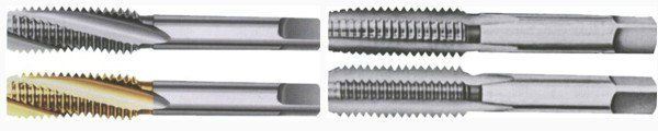
For cutting threads, special cutting tools are used - taps (cutting threads in holes), dies, lechers and clamps (cutting threads from the outside of the part).
A tap is a cylindrical cutting tool with a thread profile printed on the outer surface with grooves for removing chips. The intersection of the groove with the thread turns forms the cutting edge of the tap, which removes chips when cutting threads.
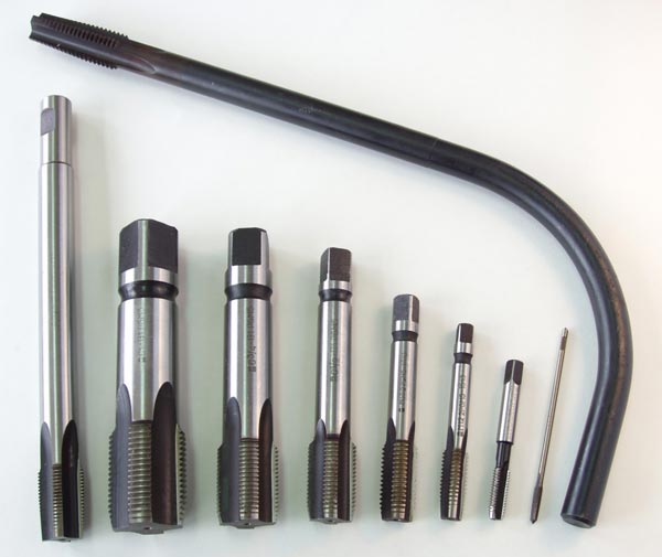
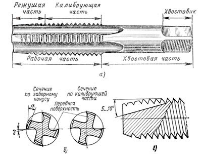
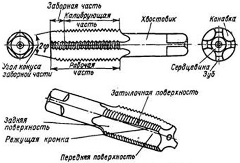
Taps are designed for cutting or calibrating threads in holes. There are hand taps, machine taps, nut taps (for cutting threads in nuts) and die taps (for cutting threads in dies). Hand taps are supplied in a set consisting of 2-3 taps; rough taps have reduced dimensions, and finishing taps have the dimensions of the full thread profile. Nut taps are made with short, long and curved shanks. The working part of the tap L consists of an intake L 1 and a calibrating L 2 part. The length of the intake (cutting) part of manual roughing taps is 4 turns, of manual finishing taps is 1.5-2 turns. The length of the intake part of machine taps when cutting through holes is 5-6 turns, and when cutting blind holes 2 turns. For nut taps, the length of the intake part is 11-12 turns. The calibration part L 2 serves to clean and calibrate the threads and ensure the correct direction. To reduce friction, the calibrating part has a slight reverse cone. The tail part of the tap L 3 is a rod; The end of the L4 shank of hand (and sometimes machine) taps has a square shape. The groove profile of the tap influences the threading process and should facilitate chip removal. Taps with three and five grooves are widely used. The rake angle of the tap is γ = 5-10 degrees when processing steel, γ = 0-5 degrees when processing cast iron and γ = 10-25 degrees when processing non-ferrous metals and their alloys. Rear angle of the tap α=4-12 degrees. Typically, taps are made with straight flutes, but in some cases the angle of inclination of the groove is γ = 8-15°, which improves the conditions for chip removal.
Taps, depending on their purpose, can be bench taps, machine taps, sliding taps, and a number of special taps, but at home we usually use simple bench taps for cutting threads by hand. Mechanic's taps, in turn, are cylindrical and conical - cylindrical taps in a set have 3 taps of the same size, they have different outer diameters, and the full thread profile can only be obtained with a finishing tap, while conical taps have the same outer diameter in the set, but they differ they are the length of the fence part.
A set of taps for manual threading usually consists of three (less often, two) tools - for roughing, intermediate and finishing. These taps are distinguished by marks next to the thread designation - these are either numbers I, II and III or horizontal marks (one, two or three).
Taps for cutting threads on machine tools are called machine taps and have a fuller profile, a different profile of the grooves and cutting edge, and a different shank shape for mounting on the machine.
The thread can be right-handed - when the nut is screwed onto the bolt clockwise - and left-handed - when the nut is screwed on counterclockwise. Accordingly, the thread cutting tool is designed to cut right-handed or left-handed metric or inch threads.
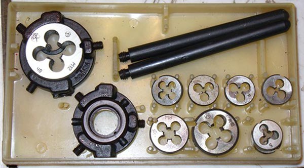
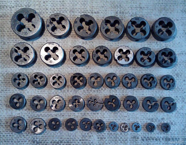
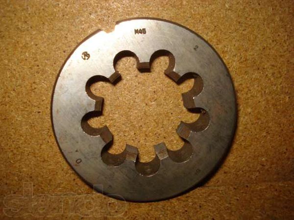
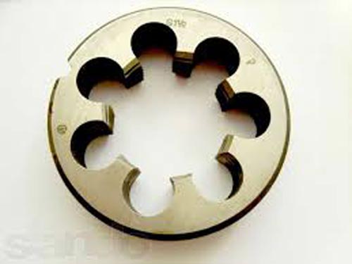
Die. To make screw threads on bolts, dies are used, which can be considered as a strongly hardened steel nut with slots that form cutting edges.
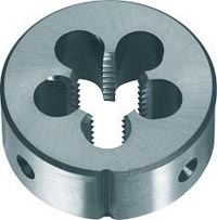
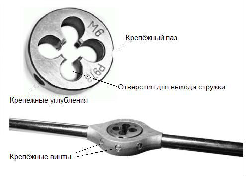
Dies are designed for cutting or calibrating external threads in one pass. The most widely used dies are for cutting threads with a diameter of up to 52 mm. The die is a hardened nut with axial holes that form cutting edges. Typically, 3-6 chip holes are made on the dies to remove chips. The thickness of the die is 8-10 turns. The cutting part of the die is made in the form of an internal cone. The length of the fence part is 2-3 turns. Angle 2φ=40-60 degrees when cutting through threads and 2φ=90 degrees when cutting threads all the way. The rake angle of standard dies is γ = 15-20 degrees. The clearance angle is α=6-8 degrees and is performed only on the intake (cutting) part.
A good, complete thread will only be achieved when the diameter of the rod or drill for preparing the hole is correctly selected. It has been established that to obtain a high-quality thread on a rod, its diameter should be 0.3-0.4 mm less than the outer diameter of the thread. Table 1 below shows the recommended rod diameters for metric threads cut with dies.
Thread diameter in mm |
Rod diameter in mm |
|
least |
greatest |
|
The end of the rod needs to be prepared by chamfering and grinding down the edge a little.
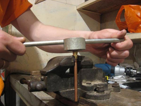
The cutting is done like this. Clamp a rod of the appropriate diameter and length in a vice, with a chamfer removed at the end. Then they put a die with dies or a screw on it and begin to screw it on with some pressure; in this case, the dies will cut a helical groove on the surface of the rod. They pass along the rod several times, gradually squeezing the dies until they get a good, complete thread. The clamp and the screw board must be rotated carefully. You can’t try to get a full cut right away, since excessive efforts may cause the hardened dies or screw board to burst. Rotate the cutting tool one to one and a half turns forward, and then reverse it in order to remove chips and provide lubrication. The dies and taps are lubricated with boiled oil (can be machine oil and soapy water).
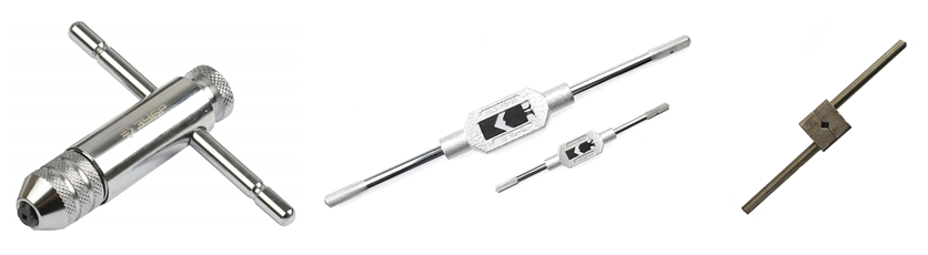
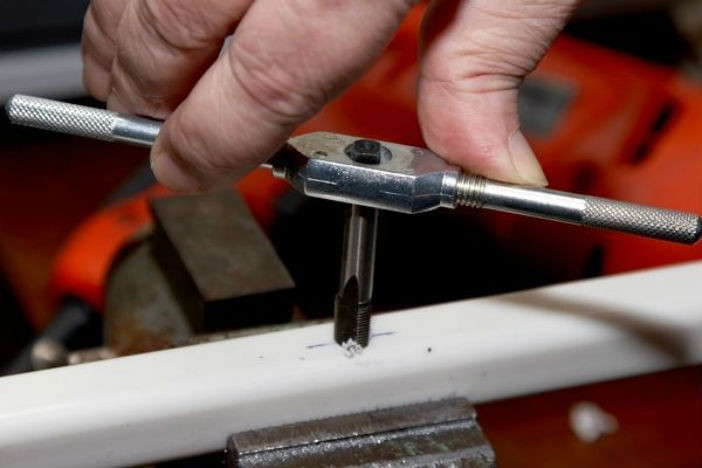
Hole cutting is usually done with two or three taps. First, take an incompletely threaded tap (1), whose threads are cut conically. This tap makes a shallow ribbon-like cut in the hole, which is deepened with a fuller tap (2), and sometimes a third one (3), almost cylindrical in shape, is made. Taps have a tetrahedral head, which is inserted into a handle with corresponding holes, or a knob.
Before cutting the thread, you need to drill a hole slightly smaller than the diameter of the tap.
Table 2 shows the diameters of holes in metal for metric threads, and for small threads (with a finer pitch) the diameters of the holes will be smaller.
Table 2. Holes for metric threads.
|
Designation |
Diameter, |
Table 3 shows the diameters of holes for cutting inch threads.
Like taps, dies and dies for cutting external threads do not have a continuous cutting surface, and thread cutting is done in sectors. To start the first turn there is an incomplete profile at the edge of the tool. The dies are solid and split - a solid die cuts the full thread profile in one pass, but for larger-diameter threads it is difficult to remove chips in one pass, and the die is made split and pressed as work progresses. The dies are inserted into die holders, where they are secured with clamping screws along conical recesses on the die body.
Lerka, or screw board, is a set of thread-cutting sockets in one tool (in one plate). Both the die and the hole in the die are designed for cutting only one thread size, but with the help of die dies you can cut threads on parts of different diameters, but with the same pitch.
Klupp is the same die (die), only without expensive, non-functional parts. A cheap holder and durable cutters - this is what a thread-cutting die is.
As you know, the entire die is made from expensive tool steel, while special strength is needed only for the cutters, which actually do the main job - cutting the thread. The cutters are attached directly to the holder, which also serves as a guide.
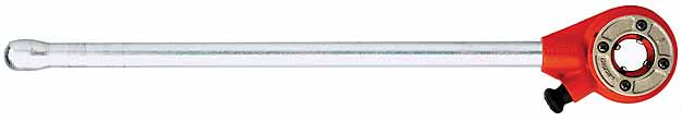
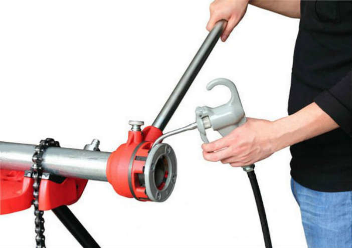
Manual clamp with ratchet
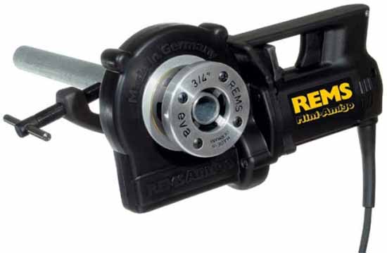
Electric plug
With a modest power of a few hundred watts, electric pipe clamps develop enormous force due to the high gear ratio.
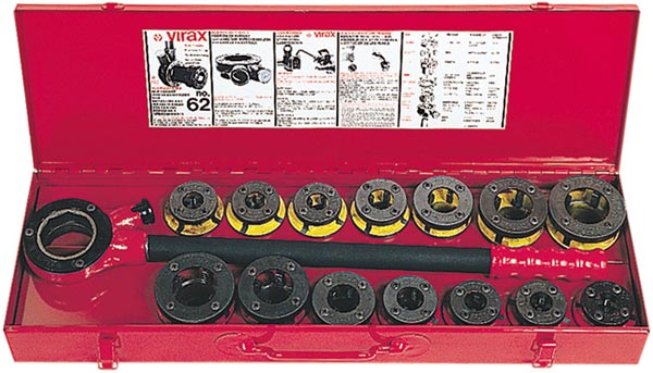
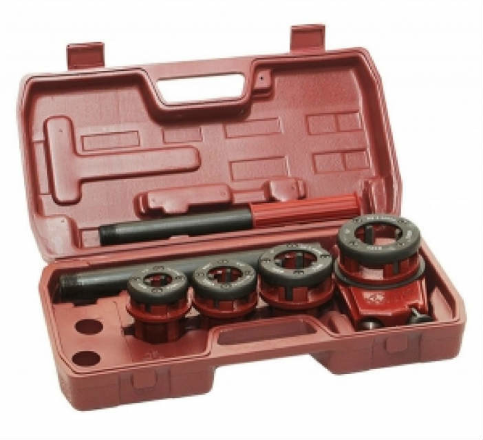
Universal die for cutting threads from 1/2" to 2". Set of dies 1/2", 3/4", 1.1/4", 1.1/2", 1.3/4", 2".
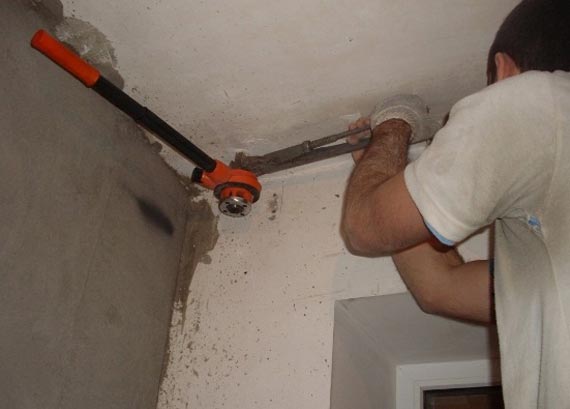
As with any business, there are subtleties to using Klupp.
- To cut the thread, you need to slightly roll the pipe and make an entry. In this respect, the die is no different from the die.
There are many ways to make the end of a pipe a little thinner: a turbine, a file; finally, you can simply flatten it slightly in a circle with a hammer on any anvil or crimp it with a gas wrench; - If, before cutting the thread, you smear a little grease, spindles, or even solarium on the pipe, the thread will not stick, it will be much easier to cut, and the cutters will last longer;
- When purchasing new cutters, go with the same manufacturer that made the holder. Otherwise, you risk encountering a stupid problem - the incisors simply won’t fit into their place;
- If you have to cut a thread on a pipe that is part of an old water supply system, be sure to hold it with a gas wrench, and the force on it should compensate for the torque when cutting the thread.
Tear off the rotten one steel pipe getting rid of a boner is much easier than it might seem from the outside.
Working with a manual clamp
Working with an electric clamp
The traditional way of joining various parts is mechanical. In relation to pipes, this means splicing them using threaded connections and corresponding fittings. This technique is mainly used when joining samples made of metals or some composite materials. What tools are used to cut threads on pipes, and how exactly this is done is the topic of this article.
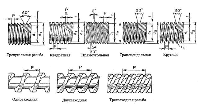
Using the table below, it’s easy to figure out how one type of thread differs from another.
The main parameters of the thread - pitch, diameters, profile height, etc. - are shown in the diagrams.
Thread cutting technology and necessary tools
Threads can be produced either manually or using machine tools. It makes no sense to consider the last option, since all the nuances of such work are well known to the specialist. In addition, thread cutting can be carried out on various models of installations, using one or another tool, depending on the type of machine.
But in everyday life or during installation work on site, threads are cut, with rare exceptions, using the simplest devices, or, as they say, with your own hands. This is more interesting for the reader, so we will focus on manual cutting methods.
External thread
Dies (dishes). The range of these products is significant. Each sample corresponds to a certain diameter of the pipe on which the cutting is made.
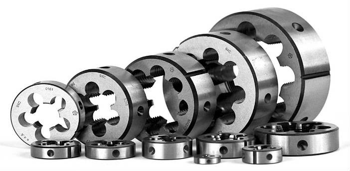
Dies vary in the quality of metal processing and are classified into products for “rough” (roughing) and “fine” (finishing) cutting. Price – from 68 rubles per sample.
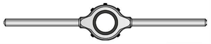
Die holders. Available in various modifications - regular, universal, with ratchet. Price – from 139 rubles.
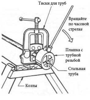
How the thread cutting device is assembled is clear from the figure.
Procedure for thread cutting
- Trimming the end of the pipe. The angle is straight with respect to the longitudinal axis. Tools – pipe cutter or.
- Preparing the surface of the site. The area where threading is intended is thoroughly cleaned of foreign deposits.
- First thread penetration. A “rough” die is placed on the pipe. For better gliding, a thin layer of oil is applied to the treated area.
- Second pass. The finishing tool is installed. It is wound onto the pipe gradually, with a systematic change in the direction of movement (clockwise, then counterclockwise). The cleanliness of the thread is visually monitored and the sufficiency of certain actions is determined.
- Quality control. In order to determine the correctness of the cutting (absence of defects, bends, etc.), any product (with the appropriate thread parameters) is installed on the pipe that can be screwed onto a given diameter - a bend, a coupling, a nut. If the sample easily passes over the entire area, the work can be considered complete.
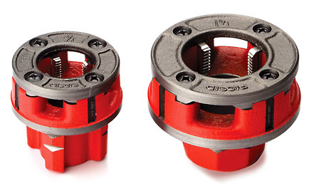
There is another tool for cutting external threads - a die. It has not been on the market for long, and not all locksmiths, even with experience, can boast of having worked with it. The device is quite simple.
The base is taken from a well-known die. But the cutting edges are insertable. Essentially, this is an assembly, while the shelf is a monolithic product. Clupps are divided into manual samples and electric models. Therefore, to increase productivity at home, there is no need to purchase (rent) a machine. The price of the clumps is from 479 rubles. They are also sold in sets, so there is a choice.
The cost of the kits is from 14,570 rubles (mechanical) and from 32,800 rubles (electrical). Manufacturers also supply samples with replaceable cutters, which makes them more convenient to use (from 798 rubles/piece). There are products that do not require any holders. They are easily turned with an open-end (gas) wrench.
Internal thread
Taps. As with dies, there is a different tool for each diameter.
Price – from 412 rubles.
Tap holders. The purpose is clear. The second name used is knob. Price – from 170 rubles.
- Trimming the end and stripping (but in this case, from the inside of the pipe).
- Lubrication of the working area.
- Primary and secondary thread penetration.
- Quality check by screwing in a suitable bolt.
Features of thread cutting on composite materials
This mainly applies to fiberglass pipes, since products made from PP, PE, and metal-plastic are connected in completely different ways. The technology for cutting threads with a tool is somewhat different from a similar operation performed on metal products. Such a connection does not have high strength, but it is considered the main one for fiberglass plastics and is used much more often than the methods of pouring the compound, pressing, profile formation and a number of others.
What is taken into account when cutting threads?
- Scheme of fiberglass reinforcement. Based on this, the direction of sample processing is determined.
- Low thermal conductivity of the composite. To prevent overheating of the tool, it is necessary to ensure effective heat removal. The method of cooling with a special liquid when working with such materials is not applicable due to the increased moisture absorption of many of them.
- Low thread cutting accuracy. Primarily due to the elasticity of fiberglass and its specific structure. If the requirements for this parameter are high, then a different processing method is selected.
- Layered structure of the material. This is especially evident with increased wear of the cutting tool. In any case, after cutting the thread, the working area is cleaned.
- Special requirements for TB. First of all, due to increased dust formation.
The technology of cutting any thread itself is not something complicated. All operations are simple. Right choice tool, adherence to the algorithm of actions and taking into account the characteristics of the processed hardware guarantee an excellent result.
Add to bookmarks
Manual pipe threading
What is thread cutting?
Threading is the processing of a hole or rod in a part, using a special thread-cutting tool to obtain an internal or external screw thread, which consists of protrusions-turns and alternating spiral grooves.
Threading is the process of machining a hole or rod in a part using a special thread-cutting tool.
Cutting is performed on pipes, nuts, bolts used in detachable connections of pipelines and various equipment parts. If you are installing piping by hand from unthreaded pipes, it will be helpful to know how to thread a pipe by hand.
The main thread elements are:
- depth;
- profile;
- profile angle;
- internal, middle and outer diameters.
Necessary concepts about carving

Scheme for cutting external cylindrical threads based on metric threads at an apex with an angle of 60 degrees.
The profile is the cross-sectional shape of a coil. Depending on the profile, rectangular, triangular, trapezoidal, etc. are distinguished. Triangular is used only when assembling sanitary systems and parts.
Also, the thread is divided depending on the direction of the turn into left and right.
Depending on the purpose of the thread, there are special and fastening threads. The fasteners are triangular, and the special ones are rectangular, etc. The triangular is a fastener, since it is cut onto fasteners: screws, nuts, bolts. Thread pitch is the distance between the bases or tops of adjacent threads.
The profile angle is the angle formed by the intersecting side edges (sides) of the turns.
The distance from the base to the top is called the depth of the thread.
The outer diameter is the distance between the points of two opposite sides of the thread. The inner diameter is the distance between the bases of opposite sides. The distance between the base and the top of the opposite side is called the average diameter.
The relationship between the depth of the thread, its pitch and the number of turns is as follows: the smaller the pitch, the smaller the depth and the greater the number of turns (threads) per unit length of the thread, and, accordingly, vice versa.
According to the system of measures, the triangular variety is inch and metric. Metric is the one that in profile looks like an equilateral triangle with an apex with an angle of 60 degrees. This type is used in mechanical engineering and instrument making. The inside diameter of the hole or outside diameter of a metric type screw is measured in millimeters, while the pitch can be measured in both millimeters and fractions thereof.
In profile, the inch version looks the same as the metric one, but the apex angle is 55 degrees. It is measured in inches and differs from the metric type in larger increments.

Metric thread in profile it looks like an equilateral triangle at the apex with an angle of 60 degrees.
The inch variety is used in the assembly of sanitary parts. It is divided into fastening and pipe. These two varieties differ in that the fastener has a larger pitch, ensuring a strong connection, and is used to cut nuts, rods, bolts and holes. And pipe is used for connecting pipes. It is shallower than the fastening one, since its depth is limited by the thickness of the pipe wall. The density of pipe threads is much higher than fastening threads due to large number turns per inch of cutting length.
External thread cutting
External threads on bolts, rods and screws are cut by hand using dies.
They are divided depending on the device:
- prismatic;
- round;
- sliding;
- whole.
Prismatic ones have a pair of identical halves, which are attached to a frame-shaped clamp with handles. On the two outer sides of these dies there are prismatic grooves intended for the prismatic protrusions of the clamp.
Prismatic dies have a pair of identical halves, which are mounted in a frame-shaped die with handles.
Sliding dies are installed in the die so that the numbers on its parts are opposite the same numbers on the frame. Otherwise it will turn out wrong. They are fastened with a persistent screw. A steel plate-cracker is placed between the die and the thrust screw so that it does not burst when pressed by the screw.
The round die is secured in the easy-holding collar with a pair or two pairs of thrust screws.
Using the sliding variety, you can make threads if there are slight deviations in the diameter of the rod, which cannot be allowed when cutting with round solid dies. A smaller rod diameter will result in an incomplete thread, while a larger diameter will result in an even thread.
Internal thread cutting
The internal thread is cut manually using taps that are inserted into the driver.
The tap has a intake part (its end), which is needed for cutting, a calibrating part (middle) - for guiding when calibrating and cutting a hole, and a tail, with a square head in cross-section, - for holding the tap in the collar when cutting.
When moving from partial to inch fasteners or full metric versions, a set of taps is used: three taps for different depths.
Basic thread positions
The connection of water pipes and gas supply pipes is carried out in such a way that cylindrical pipe threads are rolled or cut at their ends. The pipe ends are connected to each other by means of connecting pieces.
When connecting water and gas pipes, long and short cylindrical threads are used. The last two turns are called the escape. It is formed due to the design of the die, the first turns of which are countersunk. The run-out makes it possible to jam the coupling on the pipe, which guarantees the tightness of the connection with the sealing material.
The length of the short type should be slightly less than half the length of the coupling. In this case, there will be a gap of 2-3 mm between the ends of the connected pipes, which will make it possible to jam the coupling at the run. For permanent connections using fittings, a short version is used. Such a connection can only be disconnected on an installed pipeline by cutting the pipes.

The connection of water pipes and gas supply pipes is carried out in such a way that cylindrical pipe threads are rolled or cut at their ends. The pipe ends are connected to each other by means of connecting pieces.
To separate the assembled pipes without cutting them, a sweep is used. It consists of a locknut, a sleeve and a long thread. This should have such a length that when connecting the drive, you can freely screw the coupling and locknuts onto it.
The sizes of long and short threads vary depending on the diameter of the pipes.
To save metal, thin-walled pipes are used in gas supply and heating systems. Since these pipes have a smaller wall thickness than water pipes, threads are rolled onto the pipes, and the critical wall thickness of these pipes should be no less than when cutting pipe threads on water and gas pipes.
Manual thread cutting tool
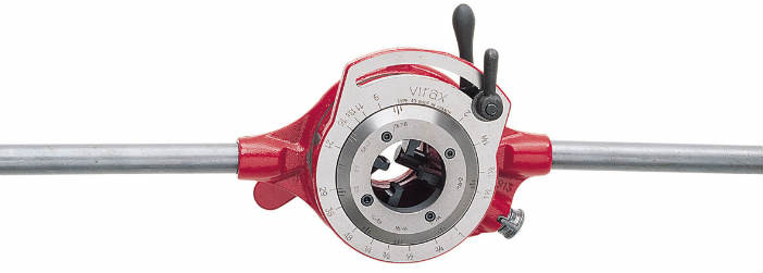
Pipe dies for cutting threads on pipes
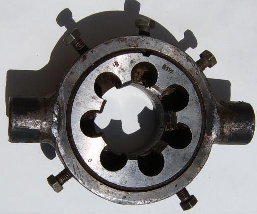
On pipes for small volumes they cut external thread manually using pipe clamps, using sliding and non-sliding dies. For this purpose, clamp the pipe into a clamp, clean the end of the pipe from scale with a file, and then lubricate the cut part with drying oil or sulfofresol. A special tool is put on the pipe - a clamp, which has sliding dies, and with light blows on the handle of the plan washer with a mallet, the guide dies are brought close to the pipe and secured with locking bolts. Also, based on the risk of the faceplate, cutting dies are attached. Then they begin to rotate the tool clockwise while simultaneously pressing on it.

In the pipe clamp body, there are four holes for the cutting die on one side and three holes on the other side for the guide.
In the pipe clamp body, there are four holes for the cutting die on one side and three holes on the other side for the guide. The guide cutting dies move apart and bring together the plan washers, which are secured with clamping rings on the body. In the planes that are adjacent to the body, the plan washers have spiral grooves into which the die pins fit. If you turn the plan washer, the pins will slide along the spiral grooves and the dies will move closer (if you turn the plan washer to the left) or, conversely, will diverge (if you turn the plan washer to the right). When the dies are installed in the required position, the plan washer is secured with clamping bolts.
Pipe dies are manufactured with a pair of sets of cutting dies: for cutting on pipes with a diameter of 15 or 20 mm and for cutting with a diameter of 25, 32, 38 and 50 mm.
For pipe dies, radial single-sided or radial double-sided dies are used. Dies are produced in sets of 4 pieces. included. Each has a designation with a diameter and a serial number from 1 to 4. Each slot on the die mounting body has corresponding numbers. The pipe has replaceable bushings for each pipe diameter, which are located in the guide flange and secured with a screw. The latter is attached with screws to the body, where the corresponding die numbers are installed.
Pipe clamps have the advantage of cleanliness of the resulting pipe threads and structural strength. Their disadvantage is the need for careful care and large mass.
When cutting a 50 mm thread, you need to rearrange the guide dies by turning them 180 ͦ, that is, with the short side inside the die (away from the pin).
Mayevsky's clamps for cutting pipe threads
A tool such as Mayevsky's clamp is also used. Mayevsky's dies have split dies that consist of two parts. A separate set of dies corresponds to a specific pipe diameter. The dies, in accordance with the number indicated on the die and in the socket, are installed in the housing socket with screws according to the marks marked on the body and on the dies for the required size. A thrust cover secured with screws is placed on the dies.
This tool is produced in two sizes: for cutting threads with a diameter of 15 and 20 mm (No. 1) and for diameters of 25 and 32 mm (No. 2).
Such a tool has the following advantages: simplicity of design and maintenance, low weight, and the ability to quickly replace dies.
Ratcheting dies for cutting threads on pipes
This tool is used for cutting threads with a diameter of 25, 20 and 15 mm. A head with replaceable dies is attached to its body. On the lower half of the head there is a ratchet wheel, which, when turned, rotates the die head and dies.
A pair of ratchets are attached to the clamp body, which are closed by the cheeks. The clamp head rotates using the handle. The cutting takes place through the rocking movement of the handle when the ratchet is turned on. At the end of cutting, the ratchet is turned on, which engages the teeth of the ratchet wheel when the handle swings and drives the round die. You can use a ratchet clamp to cut in places where a conventional tool cannot be used. This is especially true during renovation work.
To cut pipe threads, the pipe is clamped in a clamp so that the protruding end being cut is short. The long end of the pipe may bend when cutting. The end of the threaded end must be at right angles to the axis of the threaded pipe. The tool is installed on the pipe with guide rings or guide dies so that the cutting dies are 1-2 threads (turns) on the pipe. The threads on the pipes are lubricated with oil to keep the dies cool and clean. Before you start cutting with a die, you need to check whether the cutting die is installed correctly, that is, whether the number of the die matches the number of the socket in the body.
To cut, the tool is rotated and fed forward. In one pass, cutting occurs on pipes with a diameter of up to 25 mm, in two passes - for pipes with a diameter of more than 25 mm. The dies in the die are brought together with screws or a washer.
At the end of the work, the pipe clamps should be disassembled, cleaned of dirt and chips, and coated with mineral oil. Once a week, it is recommended to clean the instrument from dried and adhered oil and dirt: to do this, you need to dilute 0.5 kg of dry caustic soda in one bucket of water.
Currently, when processing threads by cutting, two processing schemes are most widely used, one of which corresponds to turning, and the second to milling.
In the scheme corresponding to turning, the tool performs a screw movement relative to the workpiece, the axis of which coincides with the axis of the thread, and the parameter is equal to the thread parameter. The movement of the helical surface of the thread of a part relative to the tool will be reduced to sliding of the surface of the part “by itself,” similar to the sliding of the helical surface of a nut along the helical surface of a bolt. As a result, the original tool surface will coincide with the surface of the part. The simplest tool that works according to the scheme under consideration is a threaded shaped cutter (Fig. 2.16). Thread cutters are used for cutting external and internal threads of acute-angled, trapezoidal, rectangular profiles. According to their design, they are divided into rod (Fig. 2.16, a), prismatic (Fig. 2.16,6) and round (Fig. 2.16, c). All of them are characterized by the fact that at the moment of final thread formation (during the last pass), their cutting edge is located on the helical surface of the thread. Therefore, the cutters under consideration differ from each other only in the shape and size of the rear surface and the methods of fastening to the machine. Round threaded cutters can be mounted or shanked. Shank cutters have a smaller diameter of the working part and are used when processing internal threads.
Threading with the help of cutters it is carried out in several passes. To reduce the number of passes and increase labor productivity with the considered processing scheme, threaded dies are used.
Threaded dies are mainly used for thread cutting fine pitch and in soft materials. The combs can cut threads in one or more passes. A thread comb consists of several threaded cutters combined in a single design. Similar to threaded cutters, threaded dies can be rod (Fig. 2.16, d), prismatic (Fig. 2.16, e) and round (Fig. 2.16, f). To distribute the load between several teeth, a cutting part with an angle φ = 25 ... 30° is created on the comb.
Due to this, the tips of the individual teeth are located at different distances from the axis of the workpiece and sequentially cut off the material of the thread root. To clean the thread, the comb has a calibrating part consisting of 4...6 teeth of the same type.
Most widespread round combs, as they are simpler to manufacture and allow a fairly large number of resharpenings. Round dies are usually designed with a helical flank, with a helix angle equal to the helix angle of the workpiece thread, and only for small helix angles of the machined thread are they manufactured with annular helices. For parts on the right
For external threads, dies with left-hand threads are used, and for parts with left-hand external threads, dies with right-hand threads are used.
Screw-threaded combs provide Better conditions cutting and easy to manufacture. During operation, the comb can be installed in different ways relative to the workpiece: in front, behind, below, above, etc. Consequently, several combs can be installed on the machine at the same time, which will increase the total length of the active cutting edges. A number of combs can be connected into a single structure. Tools that combine several threaded dies in a single design are called taps and dies.
Taps (Fig. 2.16, g) are used for processing internal threads, and dies are used for external threads. The tap is a screw mated to a thread to be cut, in which three or four chip grooves are cut and teeth are backed up. The main parameters characterizing the dimensions of the grooves are: core diameter, tooth width and angle at the non-working edge of the tooth. The recommended core diameter ranges from 0.4...0.6 of the tap diameter, tooth width 0.4...0.25 of the tap diameter, angle η = 85...70°. Taps are usually made with straight flutes. To improve chip removal, taps with a helical groove angle of 10...20° are used. It is advisable to cut threads in light alloys using taps with increased angles of inclination of chip flutes, equal to 30...40°.
The thread of the front part of the tap is cut to a cone at an angle φ, which is determined by the formula
The round die is designed for cutting low-precision external threads in one pass (Fig. 2.16, i). The working part of the round die has a cutting l 1 or intake part at both ends, which makes it possible to cut threads on both one and the other side. To distribute the cutting work between the individual cutting elements, the die has a plan angle φ on the cutting part. To calibrate the thread and ensure the correct direction in work, the die is equipped with a calibrating part l 2. Unlike taps, the die does not have a shank. For installation and fastening are provided on outer surface conical sockets into which fastening screws fit and press the die with its non-working end to the end of the die holder. After cutting a thread with taps or dies, you have to screw the tool off the part. To increase productivity when cutting external and internal threads, prefabricated “taps and dies” are used, called threading heads. The dies are mounted in the body of the threading head, which, after cutting the thread, are disengaged from the workpiece, which allows you to quickly retract the tool to its original position without reversing the rotation. When cutting external threads, the dies are removed from engagement with the workpiece by moving the dies apart, i.e., by quickly removing them from the axis of the head. When processing internal threads, the combs at the end of processing are quickly reduced to the axis of the tool.
Threading heads, depending on the location and design of the dies, are divided into heads with flat, radially installed dies (Fig. 2.16, j), heads with flat, tangentially installed dies (Fig. 2.16, l) and heads with round dies (Fig. 2.16, m) . When cutting external threads, heads with round combs are most widely used, which allow a greater number of regrinds than heads with flat combs. Internal threads are most often cut with heads with flat radial combs (Fig. 2.16, n), which simplifies the design and operation of the tool. Threading heads allow you to adjust the average diameter of the thread being cut within the required limits, install different dies in one body and, as a rule, cut a thread in one pass.
The considered tools (cutters, combs, taps, dies and heads) process threads according to the same shaping scheme, when the movement of the tool relative to the workpiece is reduced to a screw movement and the initial tool surface coincides with the surface of the thread being cut. Therefore, the profiling sections of the cutting edges of these tools are located on the same original thread surface of the part. During processing, relative screw motion can be communicated directly to the tool, which occurs when cutting threads on drilling machines taps, dies or heads. The required relative helical motion can also be obtained as a result of various combinations of tool and workpiece movements. For example, on lathe When cutting a thread, the workpiece rotates and the cutter moves progressively along the axis of the workpiece. The considered processing scheme is universal and most common when cutting threads.
Also widely used in thread processing milling. The thread milling scheme involves rapid rotation of the tool around its axis, which ensures the required cutting speed. Along with this, there is also a slow helical feed movement, the axis of which coincides with the axis of the part, and the parameter is equal to the parameter of the thread being cut.
The tool axis relative to the thread of the part can occupy different positions. Depending on the installation of the cutter axis relative to the workpiece, several types of tools and their corresponding thread milling methods are distinguished.
Disc thread cutters are used to cut trapezoidal threads with coarse pitches, large diameters, threads crossed with keyways or flats, and threads on thin-walled parts. The installation and operating diagram of a disk thread cutter is shown in (Fig. 2.17, a). The axis of the disk cutter is usually located in the S plane, perpendicular to the centerline of the thread root. In the projection onto the S plane, the axis of the part can occupy a position parallel to the axis of the cutter (Fig. 2.17, b) or inclined (Fig. 2.17, f).
In the first case, the cutter has a symmetrical profile, in the second - asymmetrical. Cutters with an asymmetrical profile as a result of the spindle tilt can be designed with a smaller diameter than cutters with a symmetrical profile. They create different cutting conditions on the side edges. By changing the angle of inclination, you can redistribute the load on the cutting edges of such cutters. These cutters can be used on machines with an inclined spindle.
The axis of the cutter can run perpendicular to the axis of the part and coincide with the axis of symmetry of the thread cavity being cut. This case corresponds to the milling of large-sized threads with finger cutters (Fig. 2.17, d), which are not widespread in industry due to their insufficient rigidity, low productivity and low durability.
Milling large-sized threads can also be produced with end mills, the axis of which, when processing short threads, is


may be perpendicular to the axis of the workpiece being cut. When cutting long threads, in order to eliminate cutting when the teeth rotate 180° from the zone in which the helical groove is formed, and also to ensure, with a relatively small diameter, correct contact between the initial surface of rotation of the cutting edges around the axis of the cutter and the thread surface without their mutual implementation, use setting the axis of the end mill at an angle to the axis of the part (Fig. 2.17, e). Finally, the axis of the cutter can run parallel to the axis of the part. This setting of the cutter axis corresponds to the processing of short threads with comb cutters. The operating diagram of a comb cutter is shown in Fig. 2.17, f. During the processing process, the cutter and the part rotate around their axes. In addition, the cutter moves progressively along its axis by a thread pitch per revolution of the part. The length of the cutter is slightly longer than the length of the thread being processed, which allows milling simultaneously along the entire length and finishing it in 1.26 revolutions of the workpiece.
Along with the considered external touch cutters, internal touch cutters are also used. Thus, for milling long threads, the vortex cutting method is used with internal touch disk cutters. The cutter is a prefabricated tool, in the annular body of which the cutters are fixed (Fig. 2.17, g). When cutting single-start threads, the tops of the cutters are located in the same plane, perpendicular to the tool axis. With the rapid rotation of the cutter, the cutting edges of the cutters describe a surface of rotation, which is brought into contact with the workpiece and, with a slow helical feed movement, forms a thread.
For milling For short threads, comb-type female cutters are used. In Fig. Figure 2.18 shows a prefabricated cutter with round combs similar to those of thread-cutting heads. The combs 4 are secured in the body 5 with sprockets 2, a bushing 1 and a screw 3. A conical shank 6 is used for fastening.
When designing female cutters, their diameter, on which the tops of the teeth are located, is chosen to be slightly larger than the outer diameter of the thread. With an increase in the difference between the diameters of the cutter and the part, the contact angle of the tool teeth with the workpiece decreases and, accordingly, productivity decreases.
A larger contact angle of the cutter teeth with the workpiece during female milling increases the number of simultaneously working teeth, the length of the contact zone between the cutting edges of the tool and the workpiece, and automatically ensures chip crushing, which is especially important when using carbide tools. This allows you to select higher feed rates per tooth, which leads to increased process productivity.
Using schemes similar to milling, threads are grinded using single-thread or multi-thread wheels.
Threading is the process of machining a hole or rod in a part, during which a specialized thread cutting tool is used to obtain an external or internal screw thread consisting of helical protrusions and alternating spiral grooves.
Cutting is done on bolts, nuts and pipes used in split pipeline systems and other design details. If the pipeline is installed manually from pipes that do not have threads, then it will be important for you to understand how you can cut threads on the product yourself.
The main characteristics of any thread are its depth, pitch, profile angle, profile, average, outer and inner diameters.
Required Thread Information
The thread profile is the cross-sectional figure near the thread. Depending on this indicator, triangular and rectangular, trapezoidal and so on are distinguished. Triangular is used exclusively for the installation of sanitary systems and its elements.
In addition, the thread is divided according to the type of direction of the turns into right and left.
Depending on the purpose of the thread, fastening and special threads are distinguished. Special ones are called rectangular ones, and triangular ones are called fastening ones. The triangular one is called fastening because it is cut only on the fastening elements of the structure: nuts, screws, bolts. The thread pitch is the distance between the tops and bottoms of adjacent turns.
The profile angle is the angle formed by the intersecting sides (edges) of the turns.
The distance from the beginning to the end of the thread is called its depth.
The outer diameter is the distance between points on two sides of the thread that lie opposite to each other. The inner diameter is the distance between the bases of opposite sides. The distance between the top and the bottom of the opposite side is called the average diameter.
According to the system of measures, the triangular type of thread is metric and inch. Metric threads have the shape of equilateral triangles at the apex with an angle of 60 degrees. This type is used in instrument making and mechanical engineering. The internal diameter of the section and the external size of the screw with metric types are calculated in millimeters, while the pitch can be calculated in millimeters and its fractions.
In profile, the inch version looks exactly the same as the metric one, but the apex angle is 55 degrees. It is calculated in inches and differs from the metric type in a different step.
The inch variety is used when assembling sanitary-type parts. It is divided into pipe and fastening. These two types differ from each other in that the fastener has a larger pitch, which guarantees a reliable connection of the structure, and is used for cutting nuts, bolts, rods and holes. Pipe is used for pipe connections. It is smaller than the fastening one because its depth is limited by the thickness of the pipe wall. The density of pipe threads is noticeably greater than fastening threads due to the numerous turns per inch of product length.
External thread cutting
External threads on rods, bolts and screws are cut by hand using dies.
Depending on the device, they are divided into round, prismatic, solid, and sliding.
Prismatic thread has a pair of identical halves, mounted in a frame-shaped clamp with handles. On a pair of outer sides of these dies there are prismatic grooves, which are intended for the prismatic protrusions of the die.
Sliding dies are located in the die so that the numbers on its sections are opposite the same numbers on the frame. Otherwise, the product will be damaged. They are attached with persistent screws. A steel plate-cracker is installed between the stop screw and the die so that the device does not burst when pressed by the screw.
Die round shape is secured in the easy-holding collar with two and four thrust screws.
Using the sliding type, you can cut threads if there are imperceptible deviations in the diameter of the rod, which is unacceptable when cutting with solid round dies. With a smaller rod diameter, an incomplete thread is cut, and with a larger diameter, an even thread is cut.
Threading from the inside
The internal thread is cut independently using taps inserted into the driver.
The tap has a fence part (its end), which is necessary for cutting, a calibrating part (middle), used for guidance when cutting a hole and calibration, and a tail part, which has a square head in cross-section, to hold the tap in the collar when cutting.
When moving from insufficient to full metric or inch fasteners, use a set of taps that includes three taps of varying depths.
Basic thread locations
The connection of pipes for supplying gas or liquids is made in such a way that cylindrical pipe threads are cut or rolled at their ends. The pipe ends are attached to each other using connecting elements.
When connecting pipes for water or gas, short and long cylindrical threads are used. The last two turns are called runaway. It is formed due to the design of the die, in which the first turns are countersunk. Thanks to the run-out, it is possible to jam the coupling on the pipe, which guarantees a reliable tightness of the connection with the sealing material.
The length of the short type should be slightly less than half the length of the coupling. Then there should be a gap of 2-3 millimeters between the ends of the connected structures, which allows the coupling to jam at the run-out. For connections that cannot be disconnected using fittings, the short version is used. Such a connection can be disconnected on an installed pipeline only by cutting the pipe products.
In order to separate the assembled pipes without cutting them, a puller is used. It includes a coupling, locknuts and a long thread, which must be of such a size that when connecting the drive, the locknuts and coupling can be easily screwed onto its surface.
The sizes of short and long threads vary depending on the size of the pipes.
In order not to use excess metal, pipes with thin walls are often used in heating systems and gas supply systems, since their external cross-section diameter is almost the same as the internal one, unlike water pipes, a pipe is usually rolled onto the pipe, with the maximum permissible wall thickness There should be no fewer similar pipes than when cutting pipe threads on gas and water pipes.
DIY thread cutting equipment
On pipes for small volumes of work, external threads can be cut with your own hands using pipe clamps, using fixed or sliding dies.

Initially, the pipe is clamped into a clamp, the end of the pipe is cleaned of scale using a file, after which the cut part is lubricated with sulforesol or drying oil.
A special tool is installed on the pipe - a clamp, which has sliding dies, and by gently hitting the handle of the faceplate with a hammer or mallet, the guide dies are brought close to the pipe, then everything is secured with bolts. In addition, based on the risk of the faceplate, cutting dies are installed. Then they begin to rotate the tool clockwise, while simultaneously pressing on it.
In the pipe clamp body, on one side there are four holes for the dilution die, and on the other side there are three holes for the guide die. The cutting guide dies are moved apart, and the faceplates are brought together, which are attached to the body with clamping rings. In the planes adjacent to the body, the faceplates have spiral grooves into which the die pins fit. If you turn the faceplate, the pins begin to slide along the spiral grooves, and the dies come closer together (if you turn the faceplate to the left) or gradually diverge (if you turn the faceplate to the right). At a time when the dies are already mounted in the required position, the faceplate is secured using clamping bolts.
Pipe dies are manufactured with a pair of sets of cutting dies: for cutting threads on pipes measuring 20 or 15 millimeters and for cutting pipes with a diameter of 25, 38, 32 and 50 millimeters.
For pipe clamps, radial double-sided or radial single-sided dies are used. Dies are produced in 4 copies per package. Each has a designation with a size and a serial number from one to four. The corresponding numbers are located at each slot on the body of the clamp. The pipe has replaceable bushings for different pipe diameters, located in the guide flange and secured with screws. The latter is secured with screws to the body, where the corresponding die numbers are installed.
Pipe clamps have the advantage of the highest quality of threads obtained on products and structural strength. The disadvantage of this equipment is its large mass and the need for serious maintenance.
When cutting a 50 mm thread, it is necessary to rearrange the guide strips, turning them 180 degrees, then with the short side inside the die.
Mayevsky technology dies for threading pipes
Equipment such as the Mayevsky clamp is often used. This device has split dies consisting of two parts. A separate part of the rams corresponds to a certain pipe size. The dies, depending on the number indicated in the socket and on the die, are mounted in the housing socket using screws according to the marks marked on the dies of the required size and on the body. A thrust cover fastened with screws is placed on the dies.

Klupp Mayevsky - appearance
This equipment is produced in two sizes: for cutting threads with a diameter of 15 and 20 millimeters and for threads with a width of 25 and 32 millimeters.
Such a device has the following advantages: low weight, ease of design and maintenance, and the ability to quickly replace dies.
Clutches with ratchet for thread cutting
This equipment is used for cutting threads of 20, 25 and 15 millimeters. A head with various dies is fixed in its body. At the bottom of the head there is a ratchet wheel that rotates the die head and die.
A pair of ratchets are installed in the clamp body, closing the cheeks. Using the handle, the clamp head can be rotated. Cutting is done by rocking the handle with the ratchet turned on. Once the cutting is complete, the ratchet is turned on, which engages the teeth of the ratchet wheel as the handle swings and drives the round die. Using a ratchet die, you can cut threads in areas of the structure where it is impossible to use traditional tools. This happens especially often when carrying out repair work.
In order to cut a pipe thread, the product is clamped in a clamp so that the protruding end to be cut is short. This is due to the fact that the long end of the pipe may become deformed when cutting. The end of the threaded end should be located at an angle equal to 90 degrees to the axis of the threaded pipe. The device is installed on the pipe with guide dies and guide rings according to such a system that the cutting dies extend onto the pipe by 1-2 turns. On pipes, the threads are lubricated with oil to keep the dies clean and cool. Before starting cutting with a die, you need to check the installation rules of the cutting die, that is, the number of the socket in the body must match the number of the die.
To cut threads, the equipment rotates and moves forward. In one circle, cutting is carried out on pipes up to 25 millimeters, in two – on pipes with a width of more than 25 mm. The dies in the die are approached using a faceplate or screws.
Upon completion of work, the clamps should be disassembled and cleaned.