1. Which pipelines are covered by the Rules?
Answer: Applies to pipelines transporting water vapor with a pressure of more than 0.07 MPa (0.7 kgf/cm2) or hot water with a temperature above 115 0 C.
Answer: For four (table).
Answer: (table).
4. Which organization gives permission to deviate from the “Rules”?
Answer: Possible deviations from the Rules must be agreed upon by the customer with Rosgortekhnadzor before concluding a contract. A copy of the approval must be attached to the pipeline passport.
5. What operating parameters of the environment are taken to determine the categories of TP and GW?
Answer: Pressure and temperature.
6. How are accidents and accidents related to the operation of pipelines investigated?
Answer: The investigation of accidents related to the operation of pipelines must be carried out in accordance with the “Regulations on the investigation and recording of industrial accidents” and the “Instructions for the technical investigation and recording of accidents that did not result in accidents at enterprises and facilities controlled by Rosgortekhnadzor "
7. Which authorities must notify an organization that has experienced an accident, fatality or group accident related to pipeline maintenance?
Answer: The administration of the owner enterprise is obliged to immediately notify the local Gospromatomnadzor body about each accident and about each accident related to the maintenance or accident of pipelines in operation registered with the State Industrial and Atomic Supervision Authority.
8. What should the organization ensure before the arrival of a representative of the Gosgortekhnadzor of Russia for the investigation?
Answer:
9. To what number of pipeline lengths does the pipeline category defined at the entrance to it belong?
Answer: The category of a pipeline, determined by the operating parameters of the medium at its inlet (in the absence of devices on it that change these parameters), applies to the entire pipeline, regardless of its length, and must be indicated in the design documentation.
11. In what cases is the pipeline owner obliged to immediately notify the Rostechnadzor body of an accident related to maintenance on pipelines in operation?
Answer: About each accident and about each serious or fatal accident associated with the maintenance or accident of pipelines in operation, registered with the state industrial supervision authorities.
12. What is the administration obliged to do, in the event of an accident on the pipeline, before a representative of Rosgortekhnadzor arrives at the enterprise?
Answer: Before the arrival of a representative of Gosgortekhnadzor of Russia to investigate the circumstances and causes of an accident or incident, the enterprise administration is obliged to ensure the safety of the entire situation of the accident (accident), if this does not pose a danger to human life and does not cause further development of the accident.
13. In what cases is the pipeline owner obliged to ensure the safety of the entire situation of the accident (accident)?
Answer: Before the arrival of a representative of Gosgortekhnadzor of Russia to investigate the circumstances and causes of an accident or incident, the enterprise administration is obliged to ensure the safety of the entire situation of the accident (accident), if this does not pose a danger to human life and does not cause further development of the accident.
14. With whom are changes to the project agreed upon, the need for which may arise during the manufacturing, repair and operation of the pipeline?
Answer: All changes in the project, the need for which may arise during the manufacturing, installation, repair and operation of the pipeline, must be agreed upon with the organization that developed the project.
15. On which pipelines are threaded connections allowed?
Answer: Threaded connections are allowed for connecting cast iron fittings on category IV pipelines with a nominal bore of no more than 100 mm.
16. Which pipelines must be covered with thermal insulation?
Answer: All pipeline elements with temperature outer surface walls above 55 0 C, located in accessible places for personnel maintenance, must be covered with thermal insulation, the temperature of the outer surface of which should not exceed 55 0 C.
17. On which pipelines at the locations of welded joints should removable sections of insulation be installed?
Answer: On category I pipelines, removable insulation sections must be installed at the locations of welded joints and metal creep measurement points.
18. Purpose of thermal insulation of TP and GW?
Answer: Thermal insulation TP and GV is intended for safety of work when servicing pipelines.
19. On which pipelines welding of a fitting is not allowed, drainage pipes, bosses and other parts in welds and pipeline elbows?
Answer: Welding fittings, drainage pipes, bosses and other parts into welds and elbows of pipelines of all categories is prohibited.
20. For which pipelines can welded sector elbows be used?
Answer: Welded sector elbows can be used for pipelines of categories III and IV.
21. In which pipelines are lap welded joints allowed?
Answer: Lap welded joints are allowed for linings that strengthen holes in pipelines of categories III and IV.
22. In butt welded joints of elements with different wall thicknesses, a smooth transition from a larger to a smaller section must be ensured. The angle of inclination of the transition surfaces should not exceed?
Answer: The angle of inclination of the transition surfaces should not exceed 15 0.
23. Underground laying of category 1 pipelines in one channel together with others is permitted process pipelines?
Answer: No.
24. When laying pipelines in semi-through tunnels (collectors), the clear height must be at least:…. ?
Answer: At least 1.5 m.
25. When laying pipelines in semi-through tunnels (collectors), the width of the passage between insulated pipelines must be at least: ...?
Answer: Not less than 0.6 m.
26. When laying pipelines in passage tunnels (collectors), the clear height must be at least:…. ?
Answer: Not less than 2.0 m.
27. How is thermal expansion at TP and HW compensated?
Answer: Due to self-compensation or by installing compensators.
28. The use of which compensators is not permitted on TP and GW?
Answer: The use of cast iron stuffing box expansion joints is not permitted on TP and GV.
29. When laying pipelines in passage tunnels (collectors), the width of the passage between insulated pipelines must be at least: ...?
Answer: Not less than 0.7 m.
30. How are the entrance hatches located in the passage channels?
Answer: Passage channels must have access hatches with ladders or brackets. The distance between hatches should be no more than 300 m, and in the case of joint installation with other pipelines - no more than 50 m. Hatches are installed at all end points of dead-end sections, at route turns and at fitting installation sites.
31. What slope is allowed for heating pipelines?
Answer: Not less than 0.002
32. What slope should the horizontal sections of the pipeline have?
Answer: Not less than 0.004
33. How many hatches should chambers have for servicing underground pipelines?
Answer: At least two hatches with ladders or brackets.
34. On which steam pipelines should displacement indicators be installed to control the expansion of steam pipelines and monitor the correct operation of the support and suspension system?
Answer: On steam pipelines with an internal diameter of 150 mm or more and a steam temperature of 300 0 C or higher.
35. What devices should be equipped in the lower sections of the pipeline section that is shut off by valves?
Answer: Drains, (Drain fittings equipped with shut-off valves, to empty the pipeline.)
36. What devices and why should be in the upper sections of the pipeline?
Answer: Vents for air removal.
37. What devices should be equipped in all sections of pipelines that are disconnected by shut-off devices for their heating and purging?
Answer: Must be equipped with bypasses, as well as a fitting with a valve at the end points.
38. Who determines the location and design of drainage devices?
Answer: Design organization.
39. For which steam pipelines is continuous condensate drainage required?
Answer: Mandatory for steam pipelines of saturated steam and for dead-end sections of steam pipelines of superheated steam, for heating networks, regardless of the state of the steam.
40. Purpose of safety devices.
Answer: Designed to prevent overpressure pipelines, the pressure should not exceed the design pressure by more than 10%.
41. To what excess pressure above the design one should safety devices be designed and adjusted at a design pressure of up to 0.5 MPa (5 kgf/cm2)?
Answer: The pressure should not exceed the calculated one by more than 10%, no more than 0.05 MPa (0.5 kgf/cm2).
42. Is it allowed to sample the medium from the pipe on which the safety device is installed?
Answer: No.
43. What accuracy class of pressure gauges should be at operating pressures up to 2.5 MPa (25 kgf/cm2)?
Answer: Not lower than 2.5
44. What accuracy class of pressure gauges should be at operating pressures of more than 2.5 MPa (25 kgf/cm2) to 14 MPa (140 kgf/cm2)?
Answer: Not lower than 1.5
45. What accuracy class of pressure gauges should be at an operating pressure of more than 14 MPa (140 kgf/cm 2)?
Answer: Not lower than 1.0
46. How is the pressure gauge scale selected?
Answer: The pressure gauge scale is selected so that at operating pressure the pressure gauge needle is in the second third of the scale.
47. The nominal diameter of pressure gauge housings installed at a height of up to 2 m from the level of the pressure gauge observation platform should be:...?
Answer: Not less than 100 mm.
48. The nominal diameter of pressure gauge housings installed at a height of 2 m to 3 m from the level of the pressure gauge observation platform should be:...?
Answer: Not less than 150 mm.
49. The nominal diameter of pressure gauge housings installed at a height of 3 m to 5 m from the level of the pressure gauge observation platform should be:...?
Answer: Not less than 250 mm.
50. The nominal diameter of pressure gauge housings installed at a height of more than 5 m should be: ...?
Answer: At least 250 mm, a reduced pressure gauge is installed as a backup.
51. Where is the red line applied indicating the permissible pressure of the pressure gauge?
Answer: On the pressure gauge scale.
52. What devices should and can be installed in front of the pressure gauge?
Answer: A three-way valve or other similar device for purging, checking and disconnecting the pressure gauge.
53. How many positions does a 3-way valve have?
Answer: 5 positions.
54. What device should be installed in front of a pressure gauge designed to measure steam pressure?
Answer: Siphon tube with a diameter of at least 10 mm.
55. What diameter should a siphon tube be installed in front of a pressure gauge designed to measure steam pressure?
Answer: Not less than 10 mm.
56. What data is indicated in the marking of fittings?
Answer: 1.Name or trademark of the manufacturer.
2. Conditional passage.
3. Conditional pressure and temperature of the medium.
5. Steel grade.
57. For what purposes are gate valves, valves at TP and GW equipped with bypass lines (bypasses)?
Answer: In order to facilitate the opening of valves and valves, as well as to warm up steam lines.
58. Which fittings must be supplied with a passport of the established form?
Answer: Fittings with a nominal bore of 50 mm or more.
59. In what cases is it allowed to install fittings whose body parts are made of bronze and brass?
Answer: At a temperature not higher than 250 0 C.
60. In which direction does the flywheel move when opening and closing the valve?
Answer: Opening the valve should be done by moving the handwheel counterclockwise, closing it clockwise.
61. Purpose of shut-off valves on pipelines.
Answer: For periodic shut-off of steam lines.
62. What should a pipeline have, the design pressure of which is lower than the pressure of the source feeding it?
Answer: A pipeline whose design pressure is lower than the pressure of the source supplying it must have a reducing device with a pressure gauge and a safety valve, which are installed on the side of the lower pressure.
63. Which devices must have automatic pressure control?
Answer: Automatic pressure control must have pressure reducing devices.
64. Purpose of a reduction cooling device?
Answer: Designed for automatic regulation of pressure and temperature.
65. Is it allowed to use electric welded pipes with longitudinal and spiral seam for TP and GW?
Answer: Yes, subject to radiographic testing or ultrasonic testing of the weld along its entire length.
66. By what percentage can the coefficients of linear expansion of fasteners and flanges differ?
Answer: Should not exceed 10%, with more than 10% allowed in cases justified by strength calculations, and also if the design temperature of the fastener does not exceed 50 0 C.
67. Is it allowed to use steels with different linear expansion coefficients for the manufacture of fasteners and flanges?
Answer: YES - allowed in cases justified by strength calculations, and also if the design temperature of the fastener does not exceed 50 0 C.
68. Which organization develops the technology used to manufacture pipelines and their elements?
Answer:
69. Which organization is developing technology for repairing pipelines and their elements?
Answer: Manufacturer (design organization).
70. Which organization develops the technology used to install pipelines and their elements?
Answer: The manufacturer or a specialized installation or repair organization before starting the relevant work.
71. What welding technologies should be used in the manufacture, installation and repair of transformer substations and hot water supply units?
Answer: Overlapping, end-to-end, in a tee, touching, in a corner, stepped, in a bevel.
72. What methods are non-destructive methods for testing materials and welded joints?
Answer: Visual and measuring, radiographic, ultrasonic, radioscopic, magnetic particle, steeloscopy, hardness testing, hydraulic testing.
73. What width of the seam surface and adjacent areas of the base material must be cleaned of contamination? Before a visual inspection?
Answer: Width of at least 20 mm (in both directions).
Answer: All pipelines.
75. What is the minimum test pressure during hydraulic testing of pipelines, their blocks and individual elements?
Answer: R pr = 1.25 R slave, but not less than 0.2 MPa (2 kgf/cm 2).
76. What is the maximum value of test pressure during hydraulic testing of pipelines, their blocks and individual elements?
Answer: According to the instructions, it is established by calculation in accordance with the NPO Standards.
77. What water temperature should be when conducting hydraulic testing of pipelines?
Answer: Not lower than +5 0 C and not higher than + 40 0 C.
78. What medium can be used to increase pressure when conducting hydraulic testing of pipelines?
Answer: Water.
79. At what ambient temperature should hydraulic testing of pipelines be carried out?
Answer: At positive ambient temperatures.
80. How long does a pipeline and its elements withstand test pressure during a hydraulic test?
Answer: At least 10 min.
81. How many pressure gauges are used to control pressure during hydrotesting?
Answer: Two of the same type with the same accuracy class, measurement limit and division value.
82. Which pipeline and its elements are considered to have passed the hydraulic test?
Answer: If not detected: 1) Leaks, sweating in welded joints and in the base metal. 2) visible residual deformations. 3) Cracks and signs of rupture.
83. How many times is it allowed to correct defects in the same area of a welded joint, provided that the joint is cut along the welded seam and the weld metal and heat-affected zone are removed?
Answer: No more than three times.
84. Which pipelines are subject to registration with Rosgortekhnadzor?
Answer: Pipelines of category 1 with a nominal bore of more than 70 mm, as well as pipelines of categories 2 and 3 with a nominal bore of more than 100 mm, are subject to registration with the Rosgortekhnadzor authorities before they are put into operation.
85. In what cases are TP and GV subject to re-registration?
Answer: TP and GW are subject to re-registration before putting into operation when the pipeline is transferred to another owner.
86. What documents must be submitted to the Rosgortekhnadzor authority when registering a pipeline?
Answer: 1. Pipeline passport.
2. As-built diagram of the pipeline indicating on it:
a) diameters, thicknesses of pipes, length of the pipeline;
b) Location of supports, compensators, hangers, fittings, vents and drainage devices;
c) welded joints indicating the distances between them and from them to wells and subscriber inputs;
d) location of indicators for monitoring thermal movements, devices for measuring creep.
3. Certificate of manufacture of pipeline elements.
4. Certificate of pipeline installation.
5. Certificate of acceptance of the pipeline by the owner from the installation organization.
6. Passports and other documentation for vessels that are an integral part of the pipeline.
87. What types of technical inspection should pipelines undergo before commissioning and during operation?
Answer: External and internal inspections and hydraulic testing.
88. What types of technical inspection and what pipelines are carried out by the person responsible for the good condition and safe operation?
Answer:
89. How often is an external inspection of pipelines that are not subject to registration with Rosgortekhnadzor carried out by a person responsible for good condition and safe operation?
Answer: 1. External inspection of pipelines of all categories - at least once a year.
2. External inspection and hydraulic testing of pipelines that are not subject to registration with Rosgortekhnadzor - before putting them into operation after installation, repairs related to welding, as well as when starting up pipelines after they have been in a state of conservation for more than two years.
3. Internal inspection of all pipelines - at least once every four years.
90. After how many years of TP and HW storage are external inspection and hydrotesting carried out before its start-up?
Answer: After being in a state of conservation for more than two years.
91. What types of technical examination and within what time frames should pipelines registered with Rosgortechnadzor authorities be subjected to by a specialist from the organization who has a Rosgortechnadzor license for examination? industrial safety?
Answer:
92. How often is an external inspection of pipelines registered with Rosgortekhnadzor carried out by an organization specialist who has a Rosgortekhnadzor license for industrial safety examination?
Answer: 1. External inspection and hydraulic testing - before launching a newly installed pipeline.
2. External inspection - at least once every three years.
3. External inspection and hydraulic testing - after repairs related to welding, and when starting up the pipeline after it has been in a state of conservation for more than two years.
93. Which official is required to be present during a technical examination?
Answer: Person responsible for proper condition and safe operation.
94. In what document should the results of the technical examination be recorded?
Answer: In the pipeline passport.
95. Who issues permission to operate pipelines that are not registered with Rosgortekhnadzor?
Answer:
96. Who issues permission to operate pipelines registered with Rosgortekhnadzor?
Answer:: The person responsible for the good condition and safe operation of pipelines.
97. What data is entered into special plates for each pipeline after its registration?
Answer: 1. Registration number; 2. Permitted pressure;
3. Ambient temperature; 4. Date (month and year) of the next external inspection and internal inspection (for supply pipelines).
98. Who is allowed to service TP and GW?
Answer: Persons at least 18 years of age who have been trained according to the program, have a certificate for the right to service pipelines and are familiar with the production instructions are allowed to service TP and HW.
99. How often should the knowledge of personnel servicing pipelines be tested?
Answer: At least once every 12 months, as well as when moving from one enterprise to another.
100. When should maintenance personnel check the proper functioning of pressure gauges and safety valves for pipelines with operating pressure up to 1.4 MPa (14 kgf/cm2)?
Answer: At least once per shift.
101. When should maintenance personnel check the serviceability of pressure gauges and safety valves for pipelines with operating pressures above 1.4 MPa (14 kgf/cm2) to 4.0 MPa (40 kgf/cm2)?
Answer: At least 1 time per day.
102. When should maintenance personnel check the serviceability of pressure gauges and safety valves for pipelines with operating pressure over 4.0 MPa (40 kgf/cm2)?
Answer: On time, established by the instructions approved in the prescribed manner.
103. How often should pressure gauges be checked in the manner prescribed by Gosstandart?
Answer: At least once every 12 months.
104. How often should additional checks of pressure gauges be carried out by its control owner?
Answer: : At least once every 6 months.
105. How does service personnel check the serviceability of pressure gauges during operation?
Answer: Produced using a three-way valve with a zero setting.
106. How to carry out an additional check of the pressure gauge in the absence of a control pressure gauge?
Answer: In the absence of a control pressure gauge, it is allowed to check the pressure gauge using a proven working pressure gauge that has the same scale and accuracy class as the pressure gauge being tested.
107. In what cases are pressure gauges not allowed for use?
Answer: 1. There is no seal or stamp on the pressure gauge indicating verification;
2. The verification period has expired;
3. When the pressure gauge is turned off, the needle does not return to the zero scale mark by an amount exceeding half the permissible error for a given pressure gauge;
4. The glass is broken or there is other damage to the pressure gauge, which may affect the accuracy of its readings.
108. According to what document should pipeline repairs be carried out?
Answer: Attire - clearance.
109. What needs to be done before starting repair work on the pipeline?
Answer: Turn off the steam line using valves, drain the condensate, and install plugs if necessary.
110. What inscriptions should be placed on main pipeline lines?
Answer: Line number and arrow indicating the direction of movement of the working fluid.
111. What inscriptions should be placed on branch lines near highways?
Answer: Line number, unit number and arrow indicating the direction of movement of the working fluid.
112. What inscriptions should be placed on branches from highways near units?
Answer: Line number and arrow indicating the direction of movement of the working fluid.
113. What inscriptions should be placed on the valve, gate valve and drive to them?
Answer: 1. Number or symbol shut-off or regulatory body, corresponding to operational diagrams and instructions.
2. Indicator of the direction of rotation towards closing and towards opening.
114. In what places are inscriptions made on valves, gate valves and their actuators when the steering wheel is located near the valve (gate) body?
Answer: On the valve body or insulation or on an attached plate.
115. Identification painting and warning signs of pipelines (GOST 14202)?
Answer: Water – green; steam - red; air – blue; flammable and non-flammable gases – yellow; acids – orange; alkalis – purple; flammable and non-flammable liquids – brown; other substances – gray or black.
Questions to test staff knowledge on the subject:
“Rules for the design and safe operation of vessels operating under
(Approved by the USSR State Mining and Technical Supervision on February 1, 1957)
I. General provisions
1. These Rules define the requirements for the design, manufacture, installation, maintenance and inspection of stationary pipelines and pipelines of mobile power plants transporting water steam with a pressure of over 2 ati or hot water with a temperature of over 120°. Vessels included in the pipeline system (manifolds, water coolers, etc.) must comply with the requirements of the “Rules for the design and safe operation of pressure vessels.”
2. These Rules do not apply to: a) pipelines laid on locomotives and railway cars, sea and river vessels and other floating structures; b) temporary pipelines with a service life of up to one year; c) pipelines of the 1st category with an outer diameter of less than 51 mm and pipelines of other categories with an outer diameter of less than 76 mm; d) pipelines located within the steam boiler, up to the valve on the boiler; e) drain, purge and exhaust pipelines.
3. All pipelines subject to these Rules are divided into four categories.
If there is no combination of parameters when determining the category of a pipeline, one should be guided by the environmental parameter of the pipeline (temperature or pressure), which requires its classification into the highest category.
II. Pipeline materials
4. Pipes, fittings, flanges, fastenings and other materials used for the manufacture, installation and repair of pipelines must meet the requirements of these Rules, GOST and Technical Conditions.
5. The quality of the materials used and their characteristics must be confirmed by the plant supplying the materials with appropriate certificates or passports.
Materials that do not have passports and certificates can be used only after they have been tested in accordance with GOST, TU and these Rules.
6. The use for the manufacture of pipelines of materials not provided for by these Rules, as well as the use in some cases of materials with operating parameters beyond the limits established for them by these Rules, must be approved in the prescribed manner with the State Mining and Technical Supervision Service of the USSR or the relevant Boiler Supervision Bodies as appropriate.
III. Design requirements for pipelines
General requirements
36. The organization that developed the pipeline project is responsible for the choice of the pipeline layout, the appropriateness and feasibility of the design, the correctness of strength calculations and compensation of thermal elongations, the choice of laying system, drainage, as well as in general for the project and its compliance with the requirements of these Rules.
37. All design changes that may arise during the manufacturing or installation of the pipeline must be agreed upon between the organization that developed the project and the organization that requested the design change.
38. Calculation of the strength of steam and pipelines hot water must be carried out according to the “Standards for calculating elements of steam boilers for strength”, approved by the USSR State Mining and Technical Supervision.
39. The connection of parts of pipelines can be made using welding and flanges. It is allowed to connect air vents, etc. using threaded connections.
40. The bending radius of pipes, expansion joints, bends and other similar pipeline elements must be no less than the following values:
a) when bending a pipe with preliminary sand filling and heating - at least 3.5 outer diameters of the pipe;
b) when bending a pipe on a special machine without filling with sand, in a cold state - at least 4 outer diameters of the pipe;
c) when bending a pipe with semi-corrugated folds (on one side) without filling with sand, with heating gas burner- at least 2.5 outer diameters of the pipe.
Semi-corrugated bends are not allowed for category 1 pipelines;
d) for steeply bent elbows made by hot drawing and stamping - no less than the outer diameter of the pipe. Installation of steeply bent elbows is permitted on pipelines of categories 2a, 3 and 4. Bends of pipes with a radius less than those specified in paragraphs are allowed. “a”, “b” and “c”, if the bending method guarantees a thinning of the wall by no more than 15% of the thickness required by calculation.
41. If there are bends on pipelines, the distance from the nearest transverse weld to the beginning of the rounding must be no less than the outer diameter of the pipe and not less than 100 mm.
When installing steeply curved elbows (Article 40, paragraph “g”), the location of welds at the beginning of the rounding is allowed.
The length of the straight section between the welds of two adjacent bends or steeply bent elbows, as well as between the welds when welding inserts, must be at least 200 mm for a nominal pipe diameter of 150 mm and above, and at least 100 mm for a nominal pipe diameter of up to 150 mm. It is allowed to weld steeply bent elbows without a straight section between them.
For pipelines of categories 2nd paragraph “a”, 3rd and 4th, when due to the pipeline design and installation conditions it is not possible to implement the minimum pipe bending radii specified in Art. 40, as well as for pipelines of the same categories with a diameter of more than 400 mm, it is allowed to use elbows, bends, etc., welded from separate sectors of pipes and sheet steel, and for pipelines of categories 3 and 4 it is also allowed to manufacture welded crosses, forks and other shaped parts.
The pipes and sheet material used in the manufacture of the specified shaped parts must comply with the requirements of Articles 7-11 of these Rules.
42. Cast and forged fittings and shaped parts made of alloy steel intended for welding into a pipeline must have pipe sections welded to them in the factory with a length of at least 100 mm with a nominal pipe diameter of up to 150 mm and at least 200 mm with a nominal pipe diameter over 150 mm.
43. Welding of fittings on straight sections of pipelines with a ratio of the outer diameter of the fitting to the outer diameter of the pipe equal to 1, as well as the use of welded tees from pipes with the same diameter ratio is permitted for all categories of pipelines.
The design of welded tees, as well as welding of fittings into the pipeline, must be provided for by the design and checked by the design organization using strength calculations.
44. Welding fittings, bosses, drainage pipes, etc. into pipeline welds is not allowed.
45. The fittings must be installed in places convenient for maintenance and repair. Where necessary, stairs and platforms should be provided.
46. Valves and valves that require large forces to open must be equipped with bypasses and mechanical or electric drives.
Pipe laying
47. The distance from the outer surface of the insulated pipe to fixed elements (walls, columns, equipment, etc.) should be selected taking into account the possible displacement of pipes due to thermal elongation, as well as the conditions of installation, repair and maintenance and should not be less than 25 mm.
48. When laying pipelines in passage channels (tunnels), the clear passage width must be at least 500 mm, counting from the outer surface of the pipe insulation; The passage height must be at least 1800 mm. Where the fittings are located, the width of the channel must be sufficient for convenient maintenance. In cases where several pipelines are laid in passage channels, their mutual placement should ensure convenient repairs and replacement of individual parts.
49. Chambers of non-passable channels must have dimensions sufficient to service expansion joints, valves and other fittings. The minimum width of side passages must be at least 500 mm. The height of the chamber must be at least 1800 mm.
50. Passage channels must be equipped with hatches. The distance between hatches should be no more than 300 m. At each hatch, inside the channel, ladders or brackets must be installed.
51. Together with pipelines of the 2nd, 3rd and 4th categories, it is allowed to lay other pipelines (oil pipelines, air pipelines, etc.), with the exception of pipelines with chemically caustic, toxic and flammable volatile substances.
The joint installation of category 1 steam pipelines with product pipelines is prohibited.
52. When underground installation pipelines in traffic areas, the laying depth from the ground surface to the top of the canal structure should be at least 0.5 m. In necessary cases, laying canals to a depth of less than 0.5 m is allowed, provided that their structure is reinforced.
53. When used to naturally compensate for turns of pipelines during channelless installation, it is necessary to install non-passable channels in the corresponding sections of the route (at turns).
54. Chambers for servicing underground pipelines of categories 1, 2 and 3 must have at least two hatches with ladders or brackets. In pipeline chambers with an internal area of up to 2.5 m2, as well as in pipeline chambers of the 4th category, one hatch is allowed.
When installing cast iron fittings or cast iron compensators with a diameter of more than 150 mm on pipelines, the chambers for their maintenance must be equipped with at least two hatches, regardless of the area of the chamber.
55. When aerial laying of pipelines through streets and roadways, the height of the pipelines from ground level to the outer surface of the insulation must be at least 4.5 m, except for cases of laying through the railway track, when the distance from the rail head to the outer surface of the insulation must be at least 6 m.
56. In all cases where the distance from the bottom point of pipeline insulation to ground level is less than 1.8 m, special approaches and transition stairs must be arranged for the passage of people.
57. Horizontal sections of steam pipelines must be laid with a slope of at least 0.001, with drainage installed.
Compensation for thermal expansion when laying pipelines
58. Each section of the pipeline between fixed supports must be designed to compensate for thermal elongations.
Compensation for thermal expansion can be carried out both through self-compensation and by installing compensators.
59. The following types of compensators are allowed:
a) bent U-shaped, lyre-shaped, etc. from pipes for any pressure and ambient temperature;
b) for pipelines of categories 2, 3 and 4, it is allowed to use U-shaped expansion joints with elbows welded from sectors, as well as with steeply bent pipe bends of the same quality as straight sections;
c) steel gland seals of special design for pressures up to 16 ati;
d) lens ones - up to a pressure of 7 ati;
e) stuffing box cast iron.
60. When installed, expansion joints must be stretched by the amount specified in the design.
61. U-shaped and lyre-shaped compensators must be installed in a horizontal position. If there is no required area for such an installation, it is permissible to install compensators in a vertical or inclined position with the hinge positioned up or down, while installing drainage fittings.
62. Installed cast iron fittings must be protected from bending stresses.
Pipeline fastening
63. The structures of pipeline supports and hangers (except for the springs themselves) must be designed for the vertical load from the weight of the pipeline filled with water and covered with insulation, and, additionally, for fixed supports for the forces arising from thermal deformation of the pipelines.
64. Pipeline supports can be calculated without taking into account the weight of water. In this case, provision must be made for the use of special safety devices to unload the supports during hydraulic testing.
65. Fixed supports must be located based on the conditions of self-compensation of pipelines and count on the forces transmitted to them in the most unfavorable load case.
Pipe drains
66. Emptying of pipelines must be carried out at the lowest points of each section of pipelines disconnected by valves through drain fittings. To remove air, vents must be installed at the highest points of the pipelines.
67. All sections of steam pipelines that can be disconnected by shut-off devices must be equipped at the end points with a fitting with a valve, and at a pressure above 22 ati, with a fitting and two sequentially located valves - a shut-off and a control (drainage) valve. Steam lines for nominal pressure PN 200 and higher must be provided with fittings with a shut-off valve, a control (drain) valve and a throttle washer located in series. In cases where a section of a steam pipeline is heated in both directions, blowing should be provided at both ends of the section.
The design of drains must provide for the possibility of monitoring their operation while the pipeline is warming up.
68. The lower end points of steam lines and the lower points of their bends must be equipped with a blowing device.
69. The location of drainage points on horizontal sections of steam pipelines, as well as the design of pipeline drainage devices, is established by the design organization.
70. Continuous removal of condensate by means of condensation traps or other devices is mandatory for saturated steam lines and for dead-end sections of superheated steam lines.
For heating networks, continuous removal of condensate, regardless of the state of the steam, at the lowest points of the route is mandatory.
IV. Manufacturing and installation of pipelines
71. The manufacture of pipelines must be carried out in full accordance with the design and these Rules. Deviations from the project must be agreed upon with the design organization that developed the pipeline project.
72. The installation organization is obliged to check the presence of certificates, stamps and markings on all pipes and other materials used for the manufacture of pipelines arriving at the installation site.
73. Welded joints of pipelines must be located at a distance of at least 50 mm from the edge of the support.
74. It is prohibited to hot bend carbon steel pipes at temperatures below 700° and heat them above 1000°, and to heat alloy steel pipes at temperatures below 800°. Heat treatment of alloy pipes after bending is mandatory.
75. Movable supports and hangers of pipelines must be assembled taking into account the thermal expansion of the pipeline.
76. Pipeline suspension clamps must be shifted against the vertical position of the rod by half the amount of thermal expansion of the pipeline in the direction opposite to its movement during thermal elongation.
77. When installing them on pipeline supports and hangers, springs must be tightened in accordance with the instructions on the drawing. During installation and hydraulic testing of the pipeline, the springs must be unloaded by spacer devices.
78. When installing a drive to pipeline fittings, it should be ensured that: a) flywheels for manual control open the fittings counterclockwise and close clockwise; b) the slot in which the valve opening indicator moves did not limit its movement in extreme positions. On the indicator scale, the extreme opening positions of the valves must be marked with indelible inscriptions.
79. Cold tension of the pipeline, if it is provided for by the design, can be carried out only after: a) final fastening of the fixed supports at the ends of the section where it is necessary to carry out cold tension; b) final installation of all supports between the specified fixed supports; c) welding and heat treatment of welded joints (if necessary) in the area between the fixed supports.
V. Pipeline welding
General requirements
80. In the manufacture and installation of pipelines and their elements, it is permitted to use all industrial welding methods that ensure the quality of welded joints in accordance with the requirements of these Rules.
The technological process of welding and the control procedure, as well as modes and methods of heat treatment of welded joints (if necessary) must be established by the relevant production instructions developed by the manufacturer or installation organization.
81. Welders who have passed tests in accordance with the Rules for testing electric welders and gas welders, approved by the State Mining and Technical Supervision of the USSR, are allowed to carry out welding work on the manufacture and installation of pipelines.
Inspection of welded joints
100. The organization of welding control must ensure systematic verification of the quality of welded joints in accordance with the requirements of these Rules, GOST and production instructions.
101. In addition to interoperational control during the manufacturing and installation of the pipeline, quality control of welded joints should be carried out using the following methods, in accordance with GOST 3242-54, 6996-54, 7512-55 and the instructions of the Ministry of Construction of Power Plants on ultrasonic quality control of welded joints of power plant pipelines: a) external inspection of all welded joints of products; b) mechanical tests of samples cut from control joints or welded joints of products; c) metallographic examination of samples cut from control joints or welded joints of products; d) ultrasonic flaw detection; e) scanning of welded joints of products with X-rays or gamma rays; f) hydraulic testing of products.
102. Each welded joint of a pipeline, made in a factory or installation environment, must have a welder’s mark.
All types of control tests are subject to appropriate documentation.
External inspection of welds
103. External inspection of welds is carried out to identify the following external defects: lack of penetration, sagging, burns, unwelded craters, undercuts, cracks in seams or in heat-affected zones, porosity, displacement of welded elements, fracture of the pipe axis at the location of the seam, as well as inspection the correct shape and size of the welds and their compliance with drawings, standards, technical specifications or standards for the welded product.
104. Inspection of welds is carried out in accordance with GOST 3242-54 using normal and special measuring tools.
Before inspection, the weld seam and the adjacent surface of the base metal to a width of at least 200 mm on both sides of the seam must be cleaned of slag and other contaminants that make inspection difficult.
105. Assessment of the quality of the weld by external inspection must be carried out in accordance with the requirements of these Rules, technical conditions or production instructions.
Mechanical testing of welded joints
106. Mechanical tests of welded joints are carried out to determine their strength and ductility.
107. Mandatory types of mechanical tests are: a) tensile test; b) bend test; c) impact test.
Impact strength testing is mandatory when welding pipelines of categories 1 and 2 “b” with a wall thickness of the welded elements of 12 mm and above.
108. To control the quality of welded joints of the pipeline and its parts, simultaneously with the welding of the pipeline, each welder is obliged to weld control joints in the amount of 1% for carbon and low-alloy steel grades and 2% for austenitic steel grades of the total number of pipeline joints or flanges of the same type welded by him, but at least one control joint.
Metallographic studies
122. Metallographic examination is aimed at monitoring the physical continuity of welds, identifying cracks, pores, cavities, lack of penetration, slag inclusions, as well as establishing the structural characteristics of the metal in the main zones (transition, thermal influence). Metallographic examinations are mandatory for pipelines belonging to categories 1 and 2 “b”.
X-ray and gammagraphy and ultrasonic flaw detection
129. The following are subject to exposure to gamma rays or x-rays:
a) welded joints of pipelines of categories 1 and 2 “b” in the amount of 5% of the total number of production joints of pipes with an outer diameter of over 108 mm welded by each welder, but not less than one joint for each welder;
b) butt welds of fittings manufactured in accordance with Art. 43 of these Rules, for pipelines of categories 1st “c”, “d” and 2nd “b” with an outer diameter of over 108 mm. In this case, the seams must be scanned along their entire length;
c) welding seams of fittings into pipelines of categories 1 “c”, “d” and 2 “b” with an outer diameter of over 108 mm with a ratio of their outer diameters exceeding 0.6.
Instead of scanning butt welds of pipelines made of carbon and low-alloy steels of the perlite class, with a wall thickness of 15 mm or more, ultrasonic flaw detection is allowed.
130. Butt welds are rejected if the following defects are revealed when examined with X-rays or gamma rays:
a) cracks of any size and direction;
b) lack of penetration along the cross-section of the seam;
c) lack of penetration at the top of the seam in joints accessible for welding only on one side, without a backing, with a depth of more than 15% of the wall thickness, if it does not exceed 20 mm, and more than 3 mm - with a wall thickness of more than 20 mm.
d) slag inclusions or shells according to gr. A and B GOST 7512-55, the size of the seam depth is more than 10% of the wall thickness, if it does not exceed 20 mm and more than 3 mm with a wall thickness of more than 20 mm;
e) slag inclusions located in a chain or a solid line along the seam, according to group B of GOST 7512-55 with a total length of more than 200 mm per 1 m of seam;
f) gas pores located in the form of a continuous grid;
g) accumulation of gas pores in individual sections of the seam according to group B of GOST 7512-55 over 5 pcs. per 1 cm2 of seam area.
131. If unsatisfactory x-ray results are obtained, x-raying of twice the number of joints is carried out. If additional X-raying reveals unacceptable defects, then all pipeline joints welded by this welder will be X-rayed.
Hydraulic testing of welded pipeline elements
132. Hydraulic testing of welded pipeline elements is carried out to check the strength and tightness of welded joints.
133. Block pipeline assemblies and individual welded elements must be subjected to hydraulic testing with test pressure:
a) block units of steam pipelines and hot water pipelines - 1.25 working pressure;
b) welded elements of pipelines (compensators, elbows and other fittings) - pressure in accordance with GOST 356-52.
Technical inspection of pipelines
143. Pipelines subject to these Rules must undergo technical inspection before putting into operation and during operation: external inspection and hydraulic testing.
Supply pipelines of steam boilers of power plants, in addition to the specified types of inspection, must be subject to internal inspection during operation.
144. Technical inspection of pipelines must be carried out by the technical administration of the enterprise within the following periods:
a) external inspection of pipelines of all categories - at least once a year;
b) external inspection and hydraulic testing of pipelines not subject to registration - before putting into operation after installation, after repairs associated with welding of joints, as well as when starting up these pipelines after they have been in a state of conservation for more than two years;
c) internal inspection of feed pipelines of steam boilers of power plants that are not subject to registration - at least once every three years.
145. Registered pipelines, in addition to the technical inspection carried out by the technical administration, must be subjected to a technical inspection by a controller engineer (inspector) within the following periods:
a) external inspection at least once every three years;
b) external inspection and hydraulic testing before putting the newly installed pipeline into operation;
c) external inspection and hydraulic testing after repairs associated with welding joints, as well as when starting up the pipeline after it has been in a state of conservation for more than two years;
d) internal inspection of supply pipelines of steam boilers of power plants, with the exception of those specified in Art. 144 p. “c” - at least once every three years.
146. External inspection of pipelines laid openly or in through channels can be carried out without removing the insulation.
External inspection of pipelines when laid in non-passage channels or when laying without channels is carried out by opening the soil of individual sections and removing insulation at least every two kilometers of the pipeline length
The inspection engineer (inspector), if he has doubts about the condition of the walls or welds of the pipeline, may require partial or complete removal of the insulation.
147. Newly installed pipelines are subject to external inspection and hydraulic testing before applying insulation. For seamless pipes, it is allowed to carry out external inspection and hydraulic testing with applied insulation; in this case, welded joints and flange connections must not be insulated and accessible for inspection.
148. Hydraulic testing of pipelines can be carried out only after completion of all welding work, including heat treatment, as well as after installation and final fastening of supports and hangers.
149. Hydraulic testing of assembled pipelines must be carried out with a test pressure equal to 1.25 working pressure. Vessels that are an integral part of the pipeline are tested at the same pressure as the pipelines.
150. For feed pipelines, the working pressure is taken to be the pressure that the feed pumps can develop with the valves closed.
151. Test pressure during hydraulic testing of pipelines must be maintained for 5 minutes, after which the pressure must be reduced to working pressure. At operating pressure, the pipeline is inspected and the welds are tapped with a hammer weighing no more than 1.5 kg.
The results of the hydraulic test are considered satisfactory if during the test there is no pressure drop on the pressure gauge; no signs of rupture, leakage or fogging were found in welds, pipes, valve bodies, etc.
152. Hydraulic testing when monitoring the quality of the connecting welded joint of a steam pipeline or supply pipeline with an existing main, if there is only one shut-off valve between them, installed during welding, can be replaced by scanning this joint with X-rays or gamma rays.
153. Hydraulic testing of pipelines must be carried out at positive ambient temperatures. At negative ambient temperatures, it is allowed to replace the hydraulic test with a pneumatic one with the same test pressure as during the hydraulic test.
Precautions must be taken during pneumatic testing.
Tapping a pipeline under pressure during pneumatic testing is prohibited.
154. Internal inspection of supply pipelines with flanged connections, aimed at checking the condition of their internal surface, is carried out selectively, in places most susceptible to corrosion (the section of the supply pipeline between the main valve and check valve, dead-end sections, fittings, etc.) by disconnecting flange connections and inspection of the inner surface using a lamp and mirror. During each internal inspection of supply pipelines, the administration must inspect the fittings and fasteners.
Welded supply pipelines that do not have flanged connections must be checked by drilling the pipes in separate sections as directed by the person performing the inspection, gamma ray scanning, ultrasound testing, etc.
Pipeline supervision and maintenance
160. The administration of the enterprise that owns the pipeline is obliged to maintain the pipeline in accordance with the requirements of these Rules, ensuring the safety of service and reliability of its operation.
161. To supervise the condition of the pipeline and the safety of its maintenance, the management of the enterprise must appoint, by order of the enterprise, a responsible person who has the appropriate technical qualifications and practical experience. The last name, first name and patronymic of the responsible person and his signature must be contained in the pipeline passport.
162. Pipeline maintenance should be entrusted to persons trained in the technical minimum program and familiar with the pipeline layout. The knowledge of service personnel must be verified by the enterprise administration.
163. Putting the pipeline into operation and maintaining it must be carried out according to instructions approved by the management of the enterprise.
164. In boiler rooms and other rooms with pipelines, pipeline diagrams in conventional colors and instructions for starting up and servicing pipelines must be posted in a visible place. Shut-off valves and gate valves must have clearly visible arrows indicating the direction of rotation of the shut-off device flywheel (towards closing “3”, towards opening “O”) and the direction of movement of the medium.
165. In order to prevent accidents associated with the penetration of flammable gas into the channels and chambers of heating networks, as well as in order to eliminate accidents with personnel, it is necessary:
a) in gas-polluted areas of heating networks, ensure the possibility of ventilation of channels and chambers;
b) before entering chambers and channels where gas may appear, ventilate them;
c) a tour of the cells should be carried out by at least two persons;
d) when operating gas hazardous networks, use only safe light sources to illuminate the chambers;
e) if it is necessary to urgently enter the chamber, before the gas is removed from it, everyone descending must put on a hose gas mask, one end of which must be brought out; The use of filter gas masks is prohibited.
166. To prevent accidents of steam pipelines operating at temperatures of 450° and above due to residual deformations arising from creep of the pipe metal, as well as due to instability of the structure, the owner of the steam pipeline is obliged to establish careful and systematic monitoring of the growth of residual deformations and changes in the structure of the metal.
Observations, control measurements and cuttings must be carried out in accordance with the instructions of the Ministry of Power Plants for monitoring creep and structural changes in the metal of steam pipelines and superheaters.
Popular articles
Technical standard
RUSSIAN OPEN JOINT STOCK COMPANY
ENERGY AND ELECTRIFICATION "UES OF RUSSIA"
The Standard Manual (hereinafter referred to as the Manual) for the operation of steam and hot water pipelines of thermal power plants contains technical and organizational requirements aimed at ensuring the safe and efficient operation of pipelines of thermal power plants.
The manual is intended for use by organizations performing operations, maintenance, adjustment and repair of equipment at thermal power plants.
1 area of use
1.1. The manual applies to main pipelines (OKP code 31 1311, 31 1312) of thermal power plants, including pipelines of categories I and II in accordance with the classification below.
Table 1
1.2. The management establishes the procedure, rules and technical indicators for organizing the effective operation of equipment at thermal power plants while ensuring its reliability and safety.
1.3. The manual defines the methodological basis, as well as the minimum necessary technical and organizational requirements when developing production instructions for specific equipment of thermal power plants.
2.3. GPP: Main steam valve.
2.4. GI: Hydraulic test.
2.5. I: Instructions.
2.6. IPU: Pulse safety device.
2.13. Shut-off valve: Safety shut-off valve;
2.14. PC: Safety valve.
2.15. ROW: Reduction-cooling unit.
2.16. RD: Guidance document.
2.17. Rostekhnadzor: Federal Service for Environmental, Technological and Nuclear Supervision.
2.18. RTM: Guiding technical material.
2.19. SO: Organizational Standard.
2.20. SRM: Collection of guidance materials.
2.21. TI: Standard instructions.
2.22. R: Standard manual.
2.23. TPP: Thermal power plant.
2.24. C: Circular.
2.25. d y: Nominal diameter.
2.26. w additional: Permissible heating rate of the pipeline.
3. Organization of pipeline operation
3.1. The management of the owner organization operating the pipeline is responsible for the safe operation of the pipeline, monitoring its operation, for the timeliness and quality of inspections and repairs, as well as for agreeing with the author of the project on changes made to the pipeline and its design documentation.
The management of the owner organization must ensure that the pipeline is maintained in good condition and safe operating conditions.
For these purposes, the owner must:
Appoint a person responsible for the good condition and safe operation of pipelines from among the engineering and technical workers who have passed the knowledge test in the prescribed manner;
Provide engineering and technical workers with current regulatory and technical documentation, rules and guidelines for the safe operation of pipelines;
Appoint the required number of service personnel trained and certified to service pipelines;
Develop and approve instructions for personnel servicing pipelines;
Establish a procedure in which the personnel entrusted with responsibilities for servicing pipelines closely monitor the equipment assigned to them through inspections, checking the proper operation of fittings, instrumentation and safety devices; An operational log should be maintained to record the results of inspections and checks;
Establish a procedure and ensure periodicity of checking the knowledge of management and engineering workers of rules, regulations and safety instructions;
Organize periodic testing of staff knowledge of instructions;
Ensure strict compliance by engineering and technical workers with established rules, and maintenance personnel with instructions.
3.2. Responsibility for the good condition and safe operation of pipelines rests with the manager appointed by order of the enterprise, to whom the personnel servicing the pipelines is directly subordinate.
3.3. The person responsible for the good condition and safe operation of pipelines is obliged to:
Allow only trained and certified personnel to service pipelines;
Timely notify the commission for periodic and extraordinary testing of knowledge about upcoming inspections and ensure the attendance of personnel for testing knowledge;
Provide maintenance personnel with production instructions;
Ensure that service personnel undergo periodic medical examinations;
Ensure the maintenance and storage of technical documentation for the operation and repair of pipelines (passport, operational and repair logs, pressure gauge check log, etc.);
Every day on working days, check the entries in the shift log and sign in it;
Issue a written order to put pipelines into operation after checking their readiness for operation and organizing their maintenance;
Provide each pipeline put into operation with signs and inscriptions provided for in paragraphs. 7.5;
Allow for operation pipelines that meet industrial safety requirements;
Organize timely preparation for technical inspections of pipelines registered with Rostechnadzor and participate in inspections;
Conduct technical inspection of pipelines;
Carry out an external inspection of pipelines (during operation) - at least once a year;
Ensure that pipelines are taken out for repairs in accordance with the repair schedule;
Participate in surveys conducted by territorial bodies of Rostechnadzor and comply with orders issued based on survey results;
Conduct briefings and emergency drills with personnel servicing pipelines;
Establish the procedure for acceptance and delivery of shifts by pipeline maintenance personnel;
Ensure that faults or defects identified during technical inspection or diagnosis are eliminated before putting the pipeline into operation.
3.4. Persons trained in a program agreed upon in the prescribed manner, who have a certificate for the right to service pipelines and who know the instructions for their operation may be allowed to service pipelines.
3.5. Training of personnel involved in the operation of the pipeline must be organized in accordance with.
3.6. The most important type of training for operational personnel is emergency drills. Operating personnel of thermal power plants must participate in emergency drills at least once a quarter.
3.7. For pipelines and fittings, the design organization establishes an estimated service life. This information must be reflected in the design documentation and included in the pipeline passport. The operation of pipelines that have completed their assigned or calculated service life is permitted upon receipt of permission in the prescribed manner.
4. Pipeline installation
A pipeline is a set of parts and devices designed to transport a process medium. It includes straight sections, curved sections, shaped elements (tees, adapters from one diameter to another, compensators), devices and fittings for various purposes, as well as auxiliary technological lines for filling, emptying, heating and removing air.
The pipeline also includes a fire protection system that ensures the preservation of the specified pipeline route and its design movements during installation and operating conditions, thermal insulation, as well as control and protection means.
Control and protection means installed on pipelines must ensure reliable and safe operation of not only the pipeline itself, but also the technological equipment connected to it.
4.1. Pipes
4.1.1. Pipes are characterized by their main dimensions: internal or external diameter, wall thickness, bending radius of curved sections. In addition, the material and standard must be specified for them ( technical specifications) for manufacturing and conditional passage ( d v), which is approximately equal to the internal diameter of the pipe, expressed in millimeters.
The technical documentation for nominal diameters does not indicate units of measurement. In accordance with GOST 28338-89, the nominal diameters of pipes with an internal diameter from 10 to 25 mm are multiples of 5; from 40 to 80 mm are multiples of 10; from 100 to 375 are multiples of 25; from 400 to 1400 mm are multiples of 100. As an exception, nominal diameters of 32 and 450 are used.
The choice of the main pipe dimensions - internal diameter and wall thickness - is determined by strength and design calculations of the pipeline. The wall thickness of pipes and pipeline parts must be determined by strength calculations depending on the design parameters, corrosion and erosion properties of the transported medium in accordance with the current technical documentation and in relation to the current range of pipes. When choosing the wall thickness of pipes and pipeline parts, the features of their manufacturing technology must be taken into account. The completeness of the calculations must meet the requirements.
4.1.2. The possibility of changing the pressure, or operating temperature, or standard sizes of its elements under operating conditions of the pipeline must be justified by the results of strength verification calculations, the capabilities of installed safety devices and thermal automatics and agreed with a specialized design organization.
4.1.3 Pipes must be marked with the designation of the manufacturer, the mark of the technical control department, steel grade, batch number, as well as certificates certifying the size, quality of pipes, metal composition and its properties in accordance with the requirements of regulatory documents.
If there is no marking or incomplete information about the pipes specified in the certificates, the organization installing or repairing the pipeline must organize the necessary tests (pipe inspection) with the results documented in protocols and (or) conclusions of specialized organizations.
4.1.4. The quality of the pipeline assembly and the requirements for its welded joints are regulated in.
4.2. Pipe laying
4.2.1. The configuration of connecting pipe elements into a single structure must ensure:
Fulfillment of strength conditions for each pipeline element under the influence of internal pressure, own mass, mass of the transported medium and reactions of supporting elements;
Meeting the conditions for the strength of the metal of pipeline elements under the influence of forces developing during heating and expansion of pipeline sections (ensuring conditions for self-compensation of temperature expansion);
Unhindered removal of condensate, water and air;
Controlled heating and cooling of the pipeline;
Elimination of non-design restrictions on temperature expansion of pipeline sections covered with thermal insulation on the part of building structures, service areas and other pipelines;
Ease of installation, maintenance, monitoring and repair of all its elements.
4.2.2. The laying of pipeline sections must be carried out with the inclination of the pipe relative to the horizontal (slope) provided for by the design so that the spontaneous movement of condensate or water is directed to the evacuation units (fittings of drainage lines).
4.2.3. In accordance with the slope during heating, cooling or emptying, it must be at least 4 mm per 1 meter of pipeline length.
For steam pipelines, the specified slope value must be maintained until the temperature corresponding to saturation at the operating pressure of the medium. The initial slopes of the installation and cold states of horizontal sections of the pipeline must be determined by design calculations and indicated in its documentation.
4.2.4. The direction of the slopes must coincide with the direction of movement of the working medium. In the case of upward movement of the working medium through the steam pipeline, counter-direction of steam and condensate flows is allowed.
4.2.5. The presence of undrained areas (“condensate bags”) on pipelines is not allowed. If such sections are identified on the pipeline, measures must be taken to eliminate them or organize additional drainage points.
4.3. Pipeline fittings
The term “pipeline fittings” reflects a set of technical devices whose main purpose is:
In disconnecting pipelines from other pipelines or equipment connected to it (shut-off valves);
In regulating the parameters of the transported medium: flow, pressure, temperature (control valves);
In protecting pipelines or equipment connected to them from damage (protective fittings or safety devices).
Requirements for the fittings of pipelines of thermal power plants are established in.
According to the method of connection to the pipeline, the fittings are divided into flanged and with ends cut for welding. According to the control method - manual, electrified with local control and electrified with remote control.
4.3.1. Pipeline fittings are selected based on the highest possible pressure and temperature, nominal diameter, as well as the physical and chemical properties of the transported medium.
4.3.2. To ensure the possibility of regulating the heating rate of critical pipelines, as well as to reduce the pressure drop on the working parts of the shut-off or control valves, bypasses (bypass lines) must be installed parallel to it, as a rule, equipped with shut-off valves and a valve installed in series along the flow of the medium. It is also possible to install two valves in series, one of which (the first along the flow of the medium) is used as a shut-off valve, and the second as a control valve.
The flow area of the bypasses must be determined when designing the pipeline. The laying of bypass lines must ensure that there is no possibility of condensate accumulating in them during pipeline operation.
4.3.3. Fittings with nominal bore ( d y) greater than or equal to 50 must have a passport of the manufacturer, which must indicate the complete information contained in the specifications for the manufacture of critical elements: its body, cover, spindle, shutter and fasteners.
4.3.4. The fittings must be designed for strength taking into account the maximum permissible loads from pipelines. It is prohibited to use the fittings as a support for the pipeline.
4.3.5. The working elements of shut-off, shut-off and control valves and electrically driven valves designed to operate on water and steam must not change their position in the event of a power failure.
4.3.6. The fittings, in accordance with the requirements, must be clearly marked on the body, which must indicate:
Name or trademark of the manufacturer;
Conditional pass;
Conditional or working pressure and temperature of the medium;
Steel grade;
Direction of flow of the transported medium (for certain valve designs).
4.3.7. Shut-off valves must ensure that in the closed state there is no flow of medium through it (i.e. density), as well as a minimum hydraulic resistance for the transported medium in the open state. Both of these indicators for shut-off valves are standardized. Shut-off valves must be designed for the full pressure drop across the shut-off valve.
4.3.8. Incomplete opening or closing of shut-off valves leads to throttling of the transported medium and accelerated erosive wear of the working surfaces of the valve. In operating condition of the pipeline, the shut-off valves must be either completely open or closed. The use of shut-off valves as control valves is prohibited.
4.3.9. The pressing force of the working surfaces of the valve valve depends on the temperature of the spindle. Therefore, when the pipeline transitions from one thermal state to another, the pressing force must be adjusted. In particular, for valves with an electric drive, in which the shutdown current of the drive motor (in the “open” and “closed” positions) is set in the cold state of the pipeline, it is advisable to correct this indicator for the operating state of the pipeline.
4.3.10. Control valves are designed to smoothly change the parameters of the transported medium during pipeline operation (pressure, flow and temperature). Control valves include: control and throttle valves, valves.
4.3.11. The conditions of use and characteristics of the control valves must comply with its passport data. The use of control valves outside the area of application specified in the passport data is not allowed.
4.3.12. If there is an arrow on the valve body indicating the direction of flow of the transported medium, then the installation of the valve along the flow must be carried out in accordance with the direction of this arrow.
4.3.13. An electric drive with local and/or remote control must be installed on the valve in cases where:
The manual effort required to operate the valve is high;
This is required by the speed of technological operations;
Maintenance of the valves is difficult or associated with danger for operating personnel.
4.3.14. The valves must have plates with names and numbers corresponding to the numbers on the technological (working) pipeline diagrams, as well as the direction of rotation of the steering wheel in the direction of opening “O” and closing “W”. Control valves must be equipped with indicators of the degree of opening of the regulating body, and shut-off valves must be equipped with “Open” and “Closed” indicators.
4.3.15. Safety devices and protective fittings are components of a technological complex that ensures the safety of both pipelines and the equipment connected to them. Safety devices must ensure that the pressure in the pipeline and the equipment connected to it cannot increase above the established level. Safety devices include safety valves, BROU (in start and stop modes), and check valves.
4.3.16. The placement of safety devices and their contents are regulated by the requirements. The settings of safety devices and protective fittings must be carried out in accordance with the manufacturer's instructions.
4.3.17. Sampling of the medium from the pipe on which the safety device is installed is not allowed. Safety valves must have discharge pipelines that protect personnel from burns when the valves operate. These pipelines must be protected from freezing and equipped with drain lines (with recommended value d y not less than 50). Installation of shut-off devices on these drain lines is not permitted. It is also prohibited to install shut-off devices between safety devices and protected pipelines, as well as behind the safety devices themselves.
4.3.18. The designs of weight or spring safety valves must provide for the possibility of checking the serviceability of the valves during pipeline operation by forcing them to open. If an electromagnetic pulse safety device (IPD) is installed on a pipeline, it must be equipped with a device that allows forced opening of the valve remotely from the control panel.
4.3.19. Safety valves must be designed and adjusted so that the pressure in the protected element does not exceed the calculated value by more than 10%.
4.3.20. Exceeding the pressure when the safety valve is fully open by more than 10% of the design value can only be permitted if this is provided for by the strength calculation of the pipeline and the equipment connected to it.
4.3.21. If the operation of the pipeline is permitted at reduced pressure, then the safety devices must be adjusted according to this pressure, and the throughput of the devices must be checked by calculation.
4.4. Drainage pipelines and vents
4.4.1. At all low points of the pipeline where condensate may accumulate or water may remain (for feedwater pipelines), drain lines must be installed in accordance with. The pipeline must be drained into special technological equipment (drainage expanders) that has devices for periodic or continuous drainage of liquid.
Shut-off valves must be installed on the drainage lines, and at pressures above 2.2 MPa (22 kgf/cm2) - two sequential valves, the first of which must be used as a shut-off valve, the second as a control valve.
To control the heating of the pipeline and the serviceability of the drainage line, it is advisable to install a special branch into the atmosphere, equipped with a valve (inspection), between the shut-off and control valves.
Steam pipelines for a pressure of 20 MPa (200 kgf/cm2) and higher must be provided with fittings with sequentially located shut-off and control valves and a throttle washer.
The serviceability of drainage lines and their fittings largely determines the reliability of the pipeline and its durability.
4.4.2. In pipelines transporting water, the purpose of drain lines is to empty the internal volume of the pipeline. For pipelines transporting steam they are intended:
To control the passage of steam through the pipeline (through inspections);
For washing the pipeline (through revisions - into the drain funnel);
To drain condensate;
To pass steam when heating the pipeline (purge of the pipeline);
To pass small steam flows to maintain high temperatures in dead-end sections of the pipeline.
As a rule, drainage lines located at the greatest distance from the point where steam is supplied to the pipeline should combine the possibility of draining the pipeline and performing its purging.
4.4.3. The location, flow section of drainage lines, their layout and direction of flow of the removed medium are determined when designing the pipeline. The connection diagram of drainage lines from pipelines with different pressures to collection tanks (drainage expanders) should ensure that there is no possibility of blocking some flows by others, as well as the penetration of the removed medium from one pipeline into another.
4.4.4. When combining drainage lines of several pipelines or disconnected sections of the pipeline, shut-off valves must be installed on each of them.
4.4.5. The design and location of drainage expanders must exclude the possibility of incomplete drainage, as well as condensate getting back into the drained pipelines.
4.4.6. To avoid water hammer, drainage lines should be laid without lifting sections with a slope towards the collection tanks.
4.4.7. The configuration of drainage lines, as well as the design and location of their supporting elements must provide conditions for self-compensation of temperature expansion. In addition, drainage lines, their OPS, and passage points through service areas should not interfere with temperature movements of the main pipeline.
4.4.8. Dead-end sections of steam pipelines, as well as branches, which, due to various switching circuits while the equipment is operating, may end up in a non-flowing state, must be equipped with devices that allow the removal of condensate accumulating there. To do this, in areas of condensate accumulation, drainage lines must be installed for constant blowing into drain expanders (through throttling devices and condensate traps), or non-reinforcement lines connecting non-flowing and flowing volumes of the same pipeline, not separated by fittings (permanent drains). A prerequisite in the latter case must be the laying of unreinforced lines with a slope towards the flow volume.
4.4.9. When drain lines are turned on shut-off valve should open first, and the regulating one - second; When closing drain lines, the sequence of operations should be reversed. When draining condensate, both valves must be fully open to avoid wear.
4.4.10. At the upper points of the pipeline, on the upper generatrix of the pipe, vents must be installed - lines designed to remove air from the pipeline when it is filled with steam or water. Air vents must connect the pipeline to the atmosphere. The opening and closing of the air vents must be carried out by a valve.
Since air vents are installed on the upper part of the pipe, they are less susceptible to contamination and can be used as additional inspection lines.
4.4.11. Air balloons must have maintenance areas. Their routing should not allow the accumulation of condensate, in addition, the vent lines should not be a source of non-design restrictions for the temperature movements of the pipeline.
4.4.12. To prevent the formation of condensate and its entry into heated steam pipelines, the length of sections of air vents, drainage and purge pipelines from the connection fitting to the pipeline to the first shut-off valve along the medium should not exceed 250 - 300 mm. In addition, vents, drain lines, purge lines and non-reinforcement lines must be carefully insulated.
4.4.13. The fittings of vents and drainage lines must be selected for the same parameters of the working environment as the fittings of the pipeline on which they are installed.
4.5. Support-and-suspension pipeline fastening system (PSS)
4.5.1. The weight of the pipeline, its branches and fittings must be evenly distributed over supporting elements securely fastened to building structures. The supporting elements, as well as their fastening units, must be designed for the vertical load from the mass of the pipeline filled with water and covered with thermal insulation, as well as the forces resulting from thermal expansion of sections of the pipeline when it is heated. The elastic elements of the fire protection system must have standard reserves for load-carrying capacity and the range of changes in elastic properties. The loads of individual elements of the fire protection system in various states of the pipeline (installation, cold and operating) must be determined on the basis of design or verification calculations. In some cases, fire protection elements must provide protection of the pipeline from seismic, wind and vibration loads. Requirements for the state of the fire safety system of pipelines are established in. Requirements for the elements of the fire protection system in the conditions of repair work are given in.
4.5.2. The maximum load-carrying capacity of OPS elements of steam pipelines can be assigned without taking into account the mass of water required for carrying out hydraulic tests. For these cases, the design of the pipeline OPS must include special devices that take on the additional load from the mass of water.
4.5.3. Based on their design, a distinction is made between movable and fixed supporting elements. Movable support elements must allow the pipeline to move in one or more directions. Movable supporting elements include sliding and elastic (spring) supports, elastic suspensions, as well as rigid rods. Fixed supporting elements (depending on their design) must ensure blocking of linear movements or angular and linear movements of the pipeline (for all or some degrees of freedom) during its thermal expansion.
4.5.4. The arrangement of fire protection elements along the length of the pipeline should be selected during design based on the conditions of maintaining certain dimensions of the spans between the supporting elements, ensuring self-compensation of temperature expansions and the ability of building structures to absorb the forces transmitted to them under the least favorable combination of loading factors. Additional conditions are to ensure access to the welded joints of the pipeline for the purpose of their inspection.
4.5.5. For pipeline sections with temperature movements of more than 100 mm, it is recommended to use elastic OPS elements with rod lengths of at least 1.5 m.
Note:
4.5.6. Of the various designs of elastic support elements, the preferred ones are those in which the elastic support elements are installed in the cross-section of the rods and the load of which can be assessed and adjusted.
4.5.7. When installing moving elements of the fire protection system, as well as when securing them to building structures, the temperature movements of the points of fastening the supports on the pipeline must be taken into account during its transition from the installation state to the operating state. For this purpose, proactive displacements of the points of fastening of fire protection elements on pipelines and (or) building structures are carried out.
4.5.8. For pipelines that are exposed to vibration during operation, means must be provided to reduce it to a level that eliminates the possibility of emergency destruction and depressurization of the system.
4.5.9. Adjusting the load of fire alarm elements should only be carried out in a cold state of the pipeline. The technology for adjusting the load is described in.
4.6. Pipeline control and protection means
4.6.1. Pipelines must be equipped with means for measuring the pressure and temperature of the working medium. In addition, primary sensors are installed on pipelines, as well as actuator protection devices that ensure the safety of personnel, pipelines and associated equipment.
4.6.2. The scope of necessary technological measurements and protections must be provided for by the pipeline design, as well as the technical documentation of equipment manufacturers in accordance with the requirements.
4.6.3. The operation algorithm of the protections and their effect on the executive bodies located on the pipeline are determined by the equipment manufacturer and current regulatory documents.
The values of settings and time delays for protection operation are determined by the manufacturer of the protected equipment or the commissioning organization.
In case of equipment reconstruction or absence of manufacturer's data, settings and time delays are established based on test results.
4.6.4. Checking the serviceability of protections and the reaction of executive bodies must be carried out during comprehensive inspections of pipelines and equipment.
4.6.5. To ensure the reliability of the pipeline during heating and cooling operations, it is recommended to carry out additional temperature control with surface thermocouples or thermocouples placed in the base metal of the pipeline in the following areas:
In areas behind injection desuperheaters;
In areas that can become dead ends due to various circuit switching.
The most informative areas for installing single surface thermocouples are the lower generatrices of horizontal sections of pipelines near the fittings of the drainage lines (since this makes it possible to objectively evaluate the operation of the drainage lines when the pipeline is heated).
4.6.6. On steam pipelines with an internal diameter of 150 mm or more and a steam temperature of 300 °C and above, in accordance with the following, indicators must be installed to monitor the temperature expansion of sections, as well as to monitor the correct operation of fire alarm elements.
Notes:
1. Quantitative control of temperature movements using movement indicators is correct only for:
a. pipelines, the configuration and length of which provide displacement values exceeding the permissible deviations between measured and calculated values (see clause 7.2.2.);
b. indicators located at such a distance from the fixed supports that ensures the condition set out in clause 1a.
2. When the number of pipeline safety elements is from one to three, it is advisable to control movements not by temperature movement indicators, but by changing the load (settlement) of the elastic safety elements themselves or by changing the relative position of the moving parts of the sliding supports relative to their stationary parts.
3. For long steam pipelines laid on rigid supports in open areas, it is allowed to replace monitoring of temperature movements according to indicators with periodic monitoring of the technical condition of the elements of the support system.
4.6.7. The placement of temperature movement indicators must be carried out in accordance with the pipeline design. Changes in the placement of signs for ease of maintenance are permitted with permission from the design organization. When changing the design position of the indicators, new control values for temperature movements must be calculated.
4.6.8. To ensure the reliability of measurement results using temperature displacement indicators, the length of the rod attached to the pipeline should not exceed 1 m.
4.6.9. Marking of temperature displacement indicators in cold and operating states must be carried out for the temperature states of the pipeline or interconnected pipelines that meet the conditions for calculating the design control displacement values.
4.6.10. Quantitative monitoring of temperature movements of pipelines must be carried out for those operating modes for which control values for temperature movements are available.
Note:
Compliance with the conditions of clause 4.6.9. and 4.6.10. It is especially important for steam pipelines of thermal power plants with cross connections, since design control displacement values for them are usually available only for the transition from a state when all pipelines connected by a single system of temperature displacements are cold, to a state when they all have operating parameters. In intermediate cases (when some of the equipment is in working order and some is stopped), the comparison of measured and calculated movements is incorrect.
4.6.11. Temperature movement indicators must be freely accessible. If necessary, ladders and service platforms should be provided for them.
4.6.12. In accordance with pipelines made of carbon and molybdenum steel operating at temperatures from 450 °C and above, from chrome-molybdenum and chrome-molybdenum-vanadium steels operating at steam temperatures from 500 °C and above and from high-alloy heat-resistant steels at steam temperatures from 550 °C and above must be equipped with benchmarks to measure residual deformation. The number of residual deformation measurement points and their location must be determined by the pipeline design.
4.6.13. To prevent off-design modes of using injection desuperheaters located on horizontal sections of steam pipelines (behind boilers), as well as to identify their malfunctions, it is advisable to install surface thermocouples or thermocouples in the base metal behind them along the steam flow at a distance of 4 - 5 internal pipe diameters from the protective jackets . These thermocouples should be placed on the upper and lower generatrix of the pipeline. The use of thermocouples installed in the bulk of the base metal is preferable.
To control off-design operating modes of injection desuperheaters located on vertical sections of the pipeline, it is recommended to install similar thermocouples behind the curved section closest to the injection desuperheater on a horizontal or inclined section of the pipeline.
4.6.14. It is recommended to monitor the temperature difference “top-bottom” of the steam pipeline in all areas in which condensate may accumulate. For this, it is possible to use surface thermocouples or thermocouples installed in the bulk of the metal (see paragraph 4.6.5.).
4.6.15. Pressure gauges are used to measure the pressure of the medium. Requirements for them are established in.
4.6.16. In accordance with the project, monitoring of the most important technological parameters should be carried out using recording devices. It is also desirable to record and store information in a computer database.
4.6.17. For operating equipment and pipelines connected to it, measuring, control, automatic control, process protection and alarm, logical and remote control, technical diagnostic instruments must be constantly in operation to the designed extent.
4.6.18. After installation or reconstruction of technological protections, their commissioning on the equipment and associated pipelines must be carried out with the permission of the technical manager of the thermal power plant.
4.6.19. Decommissioning of serviceable technological protections is not permitted. Protections are subject to decommissioning in the following cases:
When the equipment operates in transient modes, when the need to disable the protection is determined by the operating instructions;
In the event of an obvious malfunction of the protection (disconnection must be carried out by order of the shift manager of the thermal power plant with mandatory notification to the technical manager and recorded in the operational log);
For periodic testing (if it is performed on existing equipment).
4.6.20. All cases of protection and alarm activation, as well as their failures, must be recorded in the operational log and analyzed.
4.7. Thermal insulation of pipelines
4.7.1. Thermal insulation pipeline must be carried out according to a separate project and comply with the requirements. The efficiency of the power plant (especially with increased requirements for maneuverability), the reliability of the pipeline and the safety of operating personnel largely depend on the quality of thermal insulation.
4.7.2. For thermal insulation, materials that do not cause metal corrosion should be used.
4.7.3. Thermal insulation must completely cover the pipeline, its branches and auxiliary lines and be in good condition. The temperature on the outer surface of a heat-insulated pipeline at an ambient temperature of 25 °C should not exceed 45 °C.
4.7.4. Thermal insulation of flange connections, fittings, compensators and sections of pipelines subject to periodic inspection (in areas in which there are welded joints, bosses for measuring creep, etc.) must be removable. Removable thermal insulation in its technical indicators should not be inferior to stationary thermal insulation.
4.7.5. Thermal insulation of pipelines laid in the open air, near oil tanks, oil pipelines, fuel oil pipelines, cable lines must have a metal or other coating that protects the thermal insulation from saturation with moisture or flammable petroleum products.
4.7.6. Complete or partial replacement of thermal insulation with lightweight insulation without readjusting the elastic elements of the fire protection system can lead to the appearance of zones of increased stress and cause a negative change in slopes. Therefore, changing the mass of thermal insulation requires re-calculating the loads of fire protection elements, changing the markings of temperature movement indicators and checking the pipeline slope system. It is advisable to replace the thermal insulation on the pipeline (which changes its total linear mass) along the entire length of the pipeline, since otherwise the calculated data on the optimal loading of fire protection elements will be unreliable. When replacing thermal insulation on individual sections of the pipeline (for example, bends), it is necessary to draw up a map of the location of the insulation, indicating the boundaries of sections with different linear weights of insulation in order to obtain reliable data on the optimal loading of fire protection elements.
5. Principles of organizing the operation of pipelines in non-stationary modes
5.1. Factors influencing the reliability of pipelines in unsteady conditions
5.1.1. The main factor influencing the reliability of the pipeline is the level of stress in the metal of its elements, due to:
a) internal pressure;
b) distributed and concentrated mass load, as well as the reaction of elements of the fire protection system;
c) efforts to self-compensate for temperature expansions.
Under conditions when the temperature of the medium changes, an uneven temperature field appears in the metal of the pipeline along the wall thickness, perimeter and length of the pipe, which causes additional non-stationary temperature stresses. These stresses, along with stresses from mechanical and hydrodynamic influences, determine the reliability of the pipeline in non-stationary operating conditions.
The factors specified in paragraphs a) and b), if increased beyond the norm, as well as significant hydrodynamic impacts, can cause accelerated damage to pipelines. The impact of these factors at a given (design) level, as well as other impacts on the pipeline metal, is extended over time. For high-temperature pipelines it is due to the gradual accumulation of damage in the metal from the influence of creep and low-cycle fatigue processes, and for low-temperature pipelines - fatigue phenomena.
The greatest influence of the level of effective stresses on the metal occurs in areas of structural stress concentrators in bends, welded joints, tees, as well as in nodes where the increased influence of individual factors is due to the characteristics of the operating mode, structural or acquired during operation features of these nodes.
Maintaining design parameters and, in particular, temperature is of great importance for pipelines operating under creep conditions.
5.1.1.1. Uneven temperature field across the thickness of the pipe wall.
The most important type of temperature stress is the stress caused by the temperature difference across the thickness of the pipe wall. These stresses are determined by the rate of change in the temperature of the medium, the intensity of heat transfer and the geometric characteristics of the pipe wall. The rate of change in the temperature of the medium during non-stationary operating modes, as a rule, can be influenced by the operating personnel, and, therefore, this type of stress is controllable.
5.1.1.2. Uneven temperature field around the perimeter of the pipe.
An uneven temperature field around the perimeter of the pipe causes warping of the pipeline. OPS elements resist warping, with the greatest obstacles being fixed and sliding supports, rigid rods, as well as OPS elements in which the elasticity of the springs turned out to be insufficient. As a result of force interaction, irreversible distortions of the axes of straight sections of pipelines, changes in slopes, damage to welded joints and fire protection elements, as well as changes in the loads of elastic elements of fire protection systems often occur.
A temperature field that is uneven along the perimeter of the pipe appears, in particular, when horizontal sections of pipelines are heated from a cold state to the saturation temperature. This occurs due to the unequal thickness of the condensate film along the height of the cross-section of the horizontal pipe. Uneven heating of the pipe around the perimeter also occurs when there is condensate that has not been removed from the pipeline, its accumulation in undrained zones (“condensate bags”), non-design operating modes of injection desuperheaters, etc.
Temperature unevenness along the perimeter of the section is quantified as the temperature difference “top-bottom” of the pipe. When heating the pipeline from a cold state, the permissible temperature unevenness along the perimeter of the horizontal sections is normalized and should not exceed 50 °C. In other cases, temperature unevenness along the perimeter of the section is allowed only if there are positive results of special strength calculations.
The appearance of temperature unevenness along the perimeter of steam pipelines at temperatures above the saturation temperature is, as a rule, a sign of:
Use of desuperheaters in off-design modes;
Desuperheater malfunctions;
Disadvantages of drainage.
For example, the appearance of temperature unevenness under high temperature conditions may be due to excessive water consumption for injection with relatively small steam leaks or condensate entering a heated steam pipeline from a dead-end section.
In the absence of temperature control “top-bottom of the pipe”, the appearance of temperature unevenness along the perimeter of the pipe in a non-stationary mode can be detected by a change in the position of the temperature movement indicators (usually it manifests itself in a sharp deviation of the trajectory of the indicator from the normal trajectory connecting the positions of the starting and ending marking points) .
Irreversible consequences of temperature unevenness around the perimeter of the pipe can be detected by the appearance of damage in welded joints, changes in the loads of elastic supports compared to design values, displacement of temperature displacement indicators relative to markings on coordinate plates, separation of support plates in sliding supports and a number of other signs.
5.1.1.3. An abrupt change in the temperature of the pipe wall is a thermal shock.
The thermal shock mode is a one-stage process of changing the temperature of the medium in relation to the temperature of the pipe wall. When monitoring the temperature of the pipeline metal with surface thermocouples, thermal shock looks like a short-term temperature change at a rate of up to 30 - 70 °C/min, then this rate quickly decreases.
It is possible to prevent an increase in stress due to thermal shock only in advance by creating appropriate conditions for temperature changes.
The most dangerous type of thermal shock is an abrupt decrease in temperature when a relatively cold environment hits the heated walls of a pipeline under the influence of internal pressure. In this case, the circumferential stresses from internal pressure and the temperature stresses of thermal shock in the pipe metal on its inner surface add up, creating for a short period of time the effect of a local increase in tensile stresses in the surface layer of the metal. The result of exposure to cooling thermal shocks is usually a network of cracks on the inner surface of the pipe.
When the pipeline is heated, the circumferential component of the stresses from the heating thermal shock on the inner surface of the pipe is subtracted from the stresses from the internal pressure (in this case they have different signs), and on the outer surface they add up, however, on the outer surface of the pipe the absolute value of thermal shock stresses is approximately half as much as on the inner surface. Therefore, heating thermal shock on the inner surface of the pipe is considered less dangerous. However, the absolute value of thermal stresses during heating thermal shock affects the kinetics of metal damage from low-cycle fatigue.
Thermal shock stresses are determined by:
The initial temperature difference between the wall and the medium (during phase transformations - the difference between the wall temperature and the saturation temperature at the current pressure in the pipeline);
The thickness of the pipe wall and the intensity of heat transfer.
The admissibility of changes in the temperature of the medium in relation to the wall temperature, caused by technological reasons, should be determined by special calculations performed in relation to specific conditions.
In general, any sudden changes in medium temperature relative to the pipe wall temperature should be avoided.
5.1.1.4. Water hammer.
During start-ups and shutdowns, conditions may be created in which a high-speed steam flow captures a certain amount of water (condensate). Water moving with a steam flow has a shock effect (perceived audibly as a sharp knock) in places where the flow turns, in particular, on curved sections of the pipeline and its fittings. A similar effect occurs when a flow of water captures a certain amount of steam, air or a vapor-gas mixture if it moves in a single volume.
The phenomenon of water hammer also occurs when a moving flow of water suddenly stops (for example, when shut-off valves close at a high speed). In this case, due to the inertia of the flow, there is an abrupt increase in pressure on the shut-off organ.
During water hammer, force impacts on pipeline elements can be several times greater than the design loads. The result may be damage to the pipeline, as well as its derailment. In addition, water hammer repeated at short intervals can cause resonance phenomena and destruction of the pipeline.
Phenomena close to water hammer repeated with high frequency occur when transporting a two-phase or boiling medium through a pipeline. They are also caused by alternating effects of water and steam volumes on curved sections of the pipeline. The impact on the pipeline increases with increasing heterogeneity of the flow of the two-phase medium. With significant heterogeneity (for example, when alternating steam and water volumes running one after another, occupying the entire cross-section of the pipe), this phenomenon can be attributed to water hammer; with low heterogeneity, it can be attributed to a factor causing vibration load.
Water hammers in pipelines and similar phenomena are very dangerous, so they should be avoided in every possible way. To do this, steam pipelines should be carefully drained, avoid accumulation of condensate in dead-end areas, prevent mixing of steam and water flows, smoothly open and close shut-off valves, and use various technical means to increase the homogeneity of two-phase flows (for example, devices for swirling or homogenizing the flow).
Vibration load is characterized by periodic mutual movements of parts of the pipeline, which look like rocking or shaking. It can be caused by such factors as increased flexibility of the pipeline under conditions of significant flow rates of the medium, acoustic vibrations in dead-end sections, movement of a two-phase medium, flow instability associated with the operation of pressure or flow regulators, vibration of connected equipment, etc. With a significant vibration amplitude (for example, when vibration-inducing influences are close to the natural frequencies of the pipeline), vibration load can lead to fatigue damage to pipeline elements, as well as damage (grinding) to the moving joints of the fire protection elements.
5.1.2. The effective stresses in the pipeline are relatively close to the calculated stress values in its cold and operating states.
Significant deviations in voltages operating in the cold and operating states may occur in the following cases:
If the quality of thermal insulation is unsatisfactory (since this causes an undesigned temperature difference across the wall thickness in operating condition and, as a consequence, additional temperature stresses in the metal);
When the loads of the fire protection elements differ from the calculated values (in this case, the stresses increase due to the distributed and concentrated mass of the pipeline and the reaction of the fire protection elements).
5.2. Combined unsteady modes of equipment and pipelines
5.2.1. Non-stationary modes of changes in the state of pipelines are an integral part of the non-stationary modes of the power equipment to which they are connected. The basic principles of organizing the modes of their joint heating and cooling are as follows:
Observe a certain sequence of technological operations on the equipment connected to the pipeline, as well as on the pipeline itself;
Ensure the rate of change in environmental parameters (and, consequently, the temperature of the pipeline metal) during non-stationary modes in accordance with special schedules and criteria;
Maintain synchronized heating of parallel pipelines.
Compliance with these principles in practice allows us to ensure:
Minimal fuel losses for unsteady operation;
Compliance with the conditions of strength and durability of equipment and pipelines.
5.2.2. The sequence, basic criteria for performing technological operations and schedules for changing parameters for elements of power equipment in non-stationary modes are determined by the manufacturers and are contained in the instructions for their operation. In addition, these indicators are clarified during commissioning tests of prototype equipment or other special tests.
5.2.3. When designing, based on the results of multivariate calculations performed in accordance with , graphs of permissible rates of change in the temperature of pipeline metal are determined for various parameter values and for various situations that may arise during non-stationary operating conditions. These graphs are subsequently consistent with similar graphs developed by equipment manufacturers.
5.2.4. The vast majority of modes in which power equipment starts and stops are standard.
At different stages of typical modes, the elements that determine the rate of change in metal temperature can be either the thickest-walled elements of the boiler (boiler outlet manifolds), turbines, or the pipelines themselves.
For standard modes, standard task schedules are developed that provide reliable and economical modes of changing the state of the equipment as a whole. In the process of individual testing, they are clarified in relation to the characteristics of each specific piece of equipment.
5.2.5. Typical task schedules indicate the main indicators characterizing the sequence of operations and changes in parameters depending on time and initial conditions. In particular, the most important indicator is the initial temperature of the metal of the thickest-walled boiler manifolds or steam inlet zones of the turbine cylinders.
5.2.6. The goal of TPP personnel when implementing standard modes of changing the state of equipment is to ensure the fulfillment of task schedules with a minimum deviation of parameters from the recommended values. Permissible deviations from the target schedules in accordance with are:
No more than ±20 °C at the temperature of fresh and secondary superheated steam;
No more than ±0.5 MPa for fresh steam pressure;
No more than 15 °C temperature difference between parallel pipelines.
5.2.7. The rate of change in steam temperature can be controlled by desuperheaters within the boiler, as well as by desuperheaters built into the pipelines themselves. In the absence of built-in desuperheaters, a guideline for determining the rate of change in metal temperature is the graphs of temperature changes in thick-walled equipment elements. If there are built-in desuperheaters in the circuit (i.e., with multi-stage control of the steam temperature), in order to ensure acceptable rates of metal heating, maintenance personnel must ensure both the permissible rates of change in the temperature of the collectors and the permissible rates of change in the temperature of the pipelines behind the built-in desuperheaters.
5.2.8. For temperature values of thick-walled equipment elements not provided for in the task schedules, starting operations are carried out in accordance with the task schedule for the nearest temperature state or are determined by special task schedules taking into account the permissible heating rates of each element of the technological scheme separately.
5.3. Permissible rate of change in pipeline metal temperature
5.3.1. The permissible rate of change in the temperature of pipeline metal is determined by the geometric characteristics of the pipe section (wall thickness, outer or inner diameter), the current temperature value, the metal from which the pipeline is made and the worst possible combination of other loading factors. Approximate calculated graphs of permissible heating rates for pipelines and collectors of various sizes are shown in Fig. 1 and fig. 2.
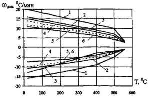
Rice. 1. Permissible speeds w of additional heating and cooling of fresh steam steam lines
(1 - 194?36 mm; 2 - 245?45 mm; 3 - 219?32 mm; 4 - 219?52 mm; 5 - 325?60 mm; 6 - 275?62.5 mm).
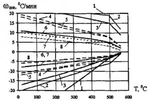
Rice. 2. Permissible speeds w of additional heating and cooling of boiler collectors
(1 - 273?30 mm; 2 - 273?40 mm; 3 - 325?45 mm; 4 - 325?60 mm; 5 - 273?60 mm; 6 - 325?75 mm; 7 - 219?70 mm; 8 - 325?85 mm).
5.3.2. Exceeding the rate of change in temperature of pipelines compared to the data given in standard task schedules can only be allowed on the basis of positive results of refined strength calculations.
5.3.3. In the absence of data on permissible rates of change in temperature of pipelines, they should be determined in accordance with the methodology, and if urgent assessment is necessary, they should be guided by the values given in Table 2.
table 2
Permissible rates of heating and cooling of steam pipeline elements
|
Name |
Temperature range, °C |
Speed, °C/min |
|
|
warming up |
cooling |
||
|
Medium pressure steam lines (up to 5 MPa) |
|||
|
Steam lines high pressure(over 5 to 22 MPa) |
|||
|
Supercritical pressure steam pipelines (over 22 MPa) |
|||
|
Steam collecting chambers of fresh steam with a pressure of more than 22 MPa, GPP housings and valves |
|||
5.3.4. When assigning the permissible rate of change in temperature of elements that are parts of a single medium transportation path (for example, the outlet manifold of a convective superheater and the steam pipeline connected to it), the smaller of the calculated values should be taken.
6. Unsteady operating modes of pipelines
The following typical modes of changing the state of technological equipment of thermal power plants are distinguished:
Warming up from a cold state;
Warming up from a cold state;
Warming up from a hot state;
Shutting down equipment to reserve;
Stop for repairs;
Emergency Stop.
The listed heating modes, as a rule, are identified by the initial temperature of the thick-walled elements of the turbine or boiler (see paragraph 5.2.4.). For pipelines, unsteady modes in the above classification are not indicative because:
Most of the operations and inspections performed within the specified modes on the main process equipment practically do not affect pipelines;
Many technological operations performed on pipelines in the modes mentioned above are practically no different from each other;
There are a number of individual operations that are specific only to pipelines, the features of which require separate consideration.
Unsteady conditions of thick-walled feedwater pipelines falling within the scope of this TR, as a rule, do not require any special operations to ensure an acceptable rate of change in metal temperature. The change in the temperature of the metal of these pipelines is usually determined by the degree of opening of the control valves of the pipelines supplying steam to the HPH in accordance with the schedule setting the change in the state of the equipment as a whole. In addition, due to the relatively low temperature of hot water and high level permissible stresses, the heating rate of pipeline metal can be quite high, which allows it to be withstood without any special conditions within the framework of compliance with the general schedule-task for maintaining a non-stationary mode.
Some exceptions are the modes related to heated thick-walled PVD collectors, in which, under certain circumstances related to circuit switching, processes close to thermal shocks can occur. However, firstly, these modes are poorly reflected in the feedwater pipelines themselves due to the high inertia of the processes occurring. Secondly, the emergence of these modes is not objective and is associated with the culture of equipment operation.
In the future, the features of a number of modes that are characteristic only of steam pipelines will be considered. In particular:
Warming up the pipeline to saturation temperature;
Warming up from saturation temperature to operating temperature;
Warming up from a temperature above the saturation temperature to operating temperature;
Shutting down equipment without cooling pipelines;
Shutdown of equipment with cooling of pipelines (including emergency shutdown);
Features of stopping pipelines for repairs.
6.1. General provisions
6.1.1. Operations to change the thermal state of equipment and pipelines must be carried out in accordance with approved schedules, instructions, and in some cases, according to special programs. The operations performed must be recorded in the operational log.
6.1.2. All deviations from the task schedules of non-stationary modes (except for emergency situations) must be approved in advance by the technical manager of the hydroelectric power station.
6.1.3 Permission to carry out operations to change the condition of the pipeline must be given by the technical manager of the workshop or his deputy. If the pipeline was under repair, then the specified permission can be given only after the responsible work manager has recorded the completion of the pipeline repair and its readiness for start-up operations.
6.1.4. Operations to change the condition of the pipeline and equipment connected to it, as a rule, must be carried out by at least two people. In this case, the first of them must perform technological operations, and the second must monitor the correctness of their implementation.
6.1.5. Analysis of the quality of non-stationary operation of equipment, and pipelines in particular, should be carried out by a permanent commission appointed by order of the head of the organization that owns the equipment. The commission appoints a chairman (chief engineer or his deputy), a person replacing him, and determines the specific responsibilities of individual members of the commission.
The analysis must be based on the materials and in accordance with the criteria set out in . The purpose of the analysis is to determine the quality of management of transient processes, including those occurring in pipelines. In all cases of violation of the sequence of operations, deviation of parameters from acceptable values, violation of specified criteria, and for pipelines, in particular, exceeding the permissible rates of temperature change or temperature difference, the causes of deviations must be identified and measures taken to prevent them.
6.2. Schemes for heating and cooling pipelines and requirements for them
A number of typical schemes for heating and cooling equipment and pipelines are given in.
6.2.1. To warm up the pipeline to a given temperature, the following is required:
Temperature and (or) flow regulated steam source;
Line for supplying steam to the pipeline;
Lines for evacuating the medium (steam or its condensate) from the pipeline; their use should be determined by the current parameters of the environment, as well as the scheme for its disposal;
Devices to which lines for evacuating the medium from a heated pipeline are connected.
6.2.2. Sources of the heating medium are usually boilers installed at thermal power plants, pipelines that are in operation, as well as special auxiliary manifolds.
When heating uncooled (hot) pipelines, an additional requirement is imposed on the steam source: the initial temperature of the steam must be greater than or equal to the temperature of the thickest-walled elements of the equipment to which the pipeline is connected, or the temperature of the thickest-walled elements of the pipeline itself.
6.2.3. Steam is supplied to the pipeline:
Directly from the boiler or from the turbine outlet without intermediate fittings:
Through valve bypasses;
Through special auxiliary lines.
6.2.4. Removal of condensate from the steam pipeline is usually carried out through drain lines into collecting manifolds and then into expansion tanks.
6.2.5. After intensive condensation of the heating steam on the walls of the pipeline is completed, its heating can continue by:
Passing steam through drain lines (the latter act as several purge lines);
Passing steam through one purge line (while closing the remaining drain lines);
Sharing of drainage lines and ROU.
6.2.6. A feature of the heating scheme for the main pipelines of block power plants is the simultaneity and consistency of operations on the boiler, pipelines and turbine. In this case, after reaching the specified values of the steam parameters, the turbine is pushed, and further heating of the main steam line, turbine and pipelines of the secondary steam superheating path is carried out synchronously with one steam flow with increasing pressure and temperature.
6.2.7. At thermal power plants with cross connections, heating schemes depend on the purpose of the pipeline and the operating scheme for its inclusion. Warming up is usually carried out in sections: from the boiler to the switching line, from the switching line to the turbine GPP, and from the turbine GPP to the SC. Sections of the switching line are heated separately. Joint heating of the main pipelines of the boiler and turbine is possible.
6.2.8. Cooling down (cooling) of pipelines is carried out:
Naturally through thermal insulation with opening of vents and drainage lines (slow cooling);
Forced (if provided for by the technological scheme), by passing a cooling medium with a temperature lower than the temperature of the pipeline wall.
6.2.9. In emergency shutdown modes of block-type thermal power plant equipment, steam evacuation from the boiler through pipelines is carried out through a high-capacity BROU. At thermal power plants with parallel connections, steam is evacuated from the boiler through the purge lines of the convective superheater.
6.2.10. Warming up of auxiliary pipelines (drainage, purge, discharge), which do not have means of monitoring the temperature state, is regulated by the degree of opening of the valves. In this case, the sequence of operations and the speed of opening the valve should be determined by local operating instructions.
6.2.11. The cooling rate of equipment connected to pipelines is usually not the same: boilers cool faster, steam pipelines cool slower, and even slower the thickest-walled parts of the turbine. This pattern is a consequence of differences in metal consumption and in the conditions for heat removal from these elements. Different cooling rates of steam and boiler pipelines for drum and once-through boilers in some cases require additional drainage operations of the intermediate boiler collectors to prevent cooling of the output collectors and steam pipelines by the resulting condensate.
6.3. Pre-start checks and operations
6.3.1. Pre-launch checks and preparatory operations must be carried out in accordance with a specific schedule.
6.3.2. Before complete or partial application of thermal insulation after installation of the pipeline, as well as after carrying out the WTO, the following are checked:
a) the quality of the installation and welding work performed;
b) compliance of the markings of all elements making up the pipeline, fittings and fire protection elements with the requirements of the project;
c) compliance with the design of the geometric dimensions of the areas, binding of the elements of the fire protection system and indicators of temperature movements;
d) slope values of horizontal sections of routes and their compliance with design values;
e) availability, compliance with the design and execution of drainage lines, vents, impulse lines; no possibility of pinching them;
f) absence of installation or temporary connections between the surfaces of sliding supports;
g) the correct assembly of fire protection elements and their operability during the transition of the pipeline from the installation to the cold and operating state;
h) compliance of the installation characteristics of the elastic elements of the fire protection system with the design or calculated data;
i) the strength of fastening of the elements of the fire protection system, the quality of welding of ears, lugs and other parts of the fire safety system, the absence of gaps and slack in clamps and rods;
j) sufficiency of the range of movements in the moving parts of the elastic supports;
k) performing installation movements of fire protection elements, anticipating their displacement under the influence of temperature expansion of the pipeline;
m) mass linear characteristics of thermal insulation and their compliance with design (calculated) values.
6.3.3. Before complete or partial application of thermal insulation after repair of the pipeline associated with cutting and re-welding sections, replacement of fittings or reconstruction of the fire protection system, the quality of the repairs performed, the integrity of the pipeline and its branches, as well as points: d), f), g), h), are checked. i), j), m) p.p. 6.3.2.
6.3.4. Before replacing the thermal insulation of the pipeline, points h), j) of Section 6.3.2 are checked, the actual slopes of the horizontal sections of the pipeline in a cold state are checked (after installation of pipelines or after WTO). If necessary, measures are taken to bring the slopes of the horizontal sections of the pipeline to the design (calculated) values according to the methodology set out in.
After replacing the thermal insulation, the quality of the work performed is checked.
6.3.5. Upon completion of the repair, after applying thermal insulation and removing blocking devices from the elastic elements of the fire protection system, the following is carried out:
Checking the serviceability of the restored thermal insulation;
Adjusting the load of the elastic elements of the fire protection system according to design (calculation) data (if this is provided for in the work plan);
Checking the compliance of the loads of the elastic elements of the fire protection system with the design (calculated) data and, if necessary, their additional adjustment;
Dismantling of scaffolding and temporary metal structures;
Checking the absence of fire hazardous objects in the immediate vicinity of the pipeline;
Checking the presence of standard gaps between the pipeline, its safety and security elements, fittings, drainage lines, vents on the one hand (taking into account future temperature movements of the pipeline) and building structures, service areas, adjacent equipment and pipelines, on the other.
6.3.6. After work related to the installation of the pipeline, in accordance with the instructions of the project, it must be purged into the atmosphere. Purge of the pipeline should also be carried out after the WTO by methods in which scale remains on the inner surface of the pipeline.
6.3.6.1. The pipeline must be purged according to a special program approved by the head of the installation, repair or commissioning organization and agreed upon with the technical manager of the thermal power plant.
6.3.6.2. When purging the pipeline, steam velocities must be ensured in it that are not less than the operating values. Purge should be carried out at operating pressure, but not more than 4 MPa.
6.3.6.3. The temporary pipeline intended for purging must be covered with thermal insulation in service areas. The support for the end part of the purge pipeline (outside the thermal power plant building) must be securely fastened. The area where the exhaust pipe of the purge pipeline exits must be fenced, and observers posted along its boundaries. The location of the exhaust into the atmosphere must be selected in such a way that there are no personnel, machinery or equipment in the hazardous area. Scaffolding and scaffolding near steam pipelines must be dismantled. When carrying out purging, fire safety regulations must be observed.
6.3.6.4. The duration of purging (in the absence of special instructions in the project) should be at least 10 minutes.
6.3.6.5. During purging, diaphragms, instruments, control and safety valves are removed from the pipeline and temporary inserts are installed instead.
6.3.6.6. During pipeline purging, fittings installed on drain lines and dead-end sections must be completely open, and after purging is completed, they must be thoroughly inspected and cleaned.
6.3.6.7. If signs of water hammer appear, the supply of steam to the purged pipeline must be stopped immediately and resumed only after it has been thoroughly drained.
6.3.6.8. Upon completion of the purge operations, the final assembly of the pipeline route and its OPS is carried out.
6.3.7. The position of the temperature movement indicators is checked for compliance with the cold state markings on the coordinate plates. If the condition of the pipeline in question (for thermal power plants with a block structure) and the associated pipelines (for thermal power plants with cross braces) meets the conditions for calculating the design control displacement values, and the marking of the coordinate plates does not correspond to the positions of the indicators or is missing, then it is carried out again.
6.3.8. After completion of the installation of the pipeline, its assembly after the WTO, major or medium repairs, shutdown in reserve, lasting more than 10 days, as well as after repairs associated with cutting and re-welding of pipeline sections, replacement of fittings, adjustment of supports and hangers, replacement of thermal insulation, After completing all the above work, the following is checked:
Readiness for operation of the pipeline fittings: connection of power supply to the electric motors, absence of clamps, chains, locks on the steering wheels and drives, reliability of fastening of the drives, complete assembly of the fitting units, absence of slack in the tightening of the nuts on the clamping bolts of the ground bushings and peripheral seals, ease of movement of the moving parts of the fittings, compliance indications of the extreme positions of shut-off valves (“open-closed”) on control panels to its actual position;
The condition of drainage lines, vents and their fittings, the absence of obstacles in them to remove condensate and air;
Integrity of impulse lines;
Readiness for operation of instrumentation, automation, protection, alarm, remote control;
Serviceability of stairs and fittings maintenance platforms.
6.3.9. After being in reserve for 3 to 10 days, or shutting down for the purpose of repairing welded joints of the pipeline, as well as replacing elements of the fastening system, before starting start-up operations, the quality of the repair work performed, the condition of thermal insulation, temperature movement indicators and fire alarm elements are checked.
6.3.10. After stopping in reserve for a period of less than 3 days without repairs, before putting the pipeline into operation, the condition of the fire alarm system elements is checked.
6.3.11. A check is made to eliminate defects and comments on the operation of pipelines previously noted in the repair log and the defect log. The results of the checks are recorded in the operational journal. If pinches, destroyed or damaged elements of the fire protection system are identified during the inspection, measures are taken to eliminate the identified defects before the start of launch operations.
6.3.12. Work is being completed, the incompleteness of which, or its implementation during operations to warm up the pipeline and equipment, can become a source of danger for maintenance and repair personnel, as well as the equipment itself. In particular:
Adjusting the load of fire alarm elements;
Hydrotesting of pipelines or their branches;
Removing plugs;
Repair of main and auxiliary valves, safety valves, start-up and release devices;
Repair of auxiliary pipelines connected to the main mains, including drainage lines, vents, instrumentation and automation lines, as well as sampling lines;
Repair and testing of protection systems, alarm systems, measuring instruments;
Testing of valves and actuators.
6.3.13. Before putting into operation the protected equipment (pipelines) after major or medium repairs, as well as after repairs in process protection circuits, the serviceability and readiness of the protections for switching on is checked. The protections are checked by testing the signal of each protection and the action of the protections on all actuators.
Before starting up the protected equipment after it has been idle for more than 3 days, the effect of the protection on all actuators is checked, as well as the operation of switching on the reserve of the process equipment. Testing must be carried out by personnel of the relevant technological workshop and personnel servicing technical equipment.
6.3.14. Testing of protections affecting equipment (including pipeline fittings) is carried out after completion of all work on the equipment involved in the operation of the protections.
6.3.15. After carrying out all types of repair work, the repair organization must prepare and submit repair documentation (diagrams, forms, welding documentation, metallographic examination protocols, hidden work performance certificates, acceptance certificates after repairs, etc.) to the relevant unit of the thermal power plant.
6.4. Warming up the pipeline to saturation temperature
Warming up of the main steam pipelines of block TPPs and TPPs with cross connections is usually carried out by supplying superheated steam to it. If the initial temperature of the pipe wall is below the saturation temperature, then steam condensation occurs on it. At the beginning of the heating process, all incoming steam condenses at the entrance to the pipeline. Then, as the wall temperature rises, the condensation zone gradually moves along the pipeline, giving way to hotter steam. The time it takes for the condensation zone to pass through the pipeline depends on its length. Intensive formation of condensate occurs over a long period of time - up to several tens of minutes.
The initial thermal shock stress in the pipeline is determined by the difference in the temperature of the pipe wall and the saturation temperature at the current pressure in the pipeline. Therefore, the lower the initial pressure of steam entering the pipeline, the smaller this difference and lower initial stresses arise in the pipeline wall.
6.4.1. Before starting operations, the shift supervisor is obliged to stop repair work and remove repair personnel from equipment located in the immediate vicinity of the heated pipeline, check the completion of all work carried out on the pipeline and its branches (see paragraph 6.3), and also make sure that absence of personnel not involved in operations near the pipeline.
6.4.2. After receiving instructions to begin pipeline heating operations from the shift supervisor, maintenance personnel are obliged to:
Open all drainage lines, as well as air vents;
If it is necessary to fill the pipeline with water, start filling while simultaneously removing air through the air vents; after water appears from the vents, close their fittings;
Upon completion of the initial drainage of the pipeline, you should make sure that there is no stream of water above the inspection drain funnels.
6.4.3. Steam supply for heating the main pipeline of the power unit is supplied from the built-in separator through a throttle valve.
When heating the section from the boiler to the switching line or from the boiler to the turbine, the steam pipelines of a thermal power plant with cross connections can be supplied directly from the boiler.
When the switching line, as well as the steam pipeline, is heated from the switching line to the cross-coupled thermal power plant turbine, steam is supplied through the bypass of the control valve separating the heated or cold pipelines.
Steam supply for heating the pipelines of secondary superheating of steam power units is carried out either from the ROU or a special expander (initial heating before the turbine is pushed), or from the turbine itself (after its push).
The steam consumption for heating the pipelines of block power plants is determined by the degree of throttling in the control valves of the pilot separator, and for pipelines of thermal power plants with cross connections - by the current productivity of the boiler or the degree of throttling in the control valves of the bypasses.
6.4.4. When supplying steam for heating through the bypass of the shut-off valve, you should fully open the shut-off valve, and then slowly and carefully open the control valve.
6.4.5. When draining the pipeline, you should ensure that the drain lines are operational. This is done by monitoring the condensate output through inspections.
6.4.6. If the drain line becomes clogged, it should be cleared by quickly closing and opening the valve. If it is not possible to remove the blockage in this way, the warm-up operations should be stopped and the pipeline should be disconnected to repair the drainage pipeline.
6.4.7. Warming up of the main and auxiliary pipelines under condensation conditions can be accompanied by their warping with the formation of counterslopes, as well as water hammer. Therefore, heating the metal to a temperature equal to the saturation temperature at operating pressure is the most critical stage of startup operations, in which it is necessary to carefully comply with the requirements of the task schedule.
6.4.8. If water hammer occurs, heating should be stopped and resumed after inspecting the pipeline, checking the drainage system and thorough drainage.
6.4.9. If there is temperature control data that the steam pipeline has begun to warm up along its entire length and steam appears from the vents, the vent fittings should be closed.
6.5. Warming up the pipeline from saturation temperature to operating temperature
6.5.1. After reaching the saturation temperature corresponding to the current pressure (a sign is the appearance of “dry” steam from the revisions), the technology for further heating to operating parameters depends on the adopted heating scheme:
If all drainage lines continue to operate in the purge mode, then heating through them is carried out to full steam parameters;
If it is intended to disconnect part of the drainage lines, then it is carried out only after residual superheating of the steam appears;
Combined heating to operating parameters is possible through purge (drainage) lines and ROU.
6.5.2. When heating the steam pipelines to the turbine, in parallel with heating the main pipeline, the section from the main steam valve (via the bypass) to the stop valve and steam transfer pipes of the turbine can be heated.
6.5.3. For power units, after drainage of the main steam pipeline is completed, the main steam valve is opened and the turbine is pushed, followed by the beginning (or continuation - see paragraph 6.4.3) of heating the secondary steam superheating path.
6.5.4. The connection of the boiler to the switching line at a TPP with cross connections should be made at a pressure slightly higher than the pressure in the switching line (to avoid “locking” the boiler). The value of this excess must be specified in the local boiler operating instructions.
For other main pipelines of hydroelectric power stations with cross connections, after the pressure rise is completed, the fittings connecting the heated section with the main equipment must be gradually opened. Next, the auxiliary pipelines must be turned off.
6.5.5. Switching on an unheated pipeline or its individual sections is prohibited.
6.5.6. During the process of heating pipelines, maintenance personnel must visually monitor the serviceability of supports, hangers and temperature movements of the pipeline.
6.5.7. Upon completion of the warm-up operations, a check must be made to ensure that the position of the temperature movement indicators corresponds to the control markings on the coordinate plates (if for the current state pipeline system this marking has been completed - see pp. 4.6.9 and 4.6.10). If a discrepancy is detected, the fire protection elements and the pipeline system should be checked for the possibility of pinching. The results of visual inspection and detected defects must be recorded in the operational log and/or defect log.
6.6. Warming up the pipeline from an uncooled (hot) state
6.6.1. After receiving instructions to begin pipeline heating operations from the shift supervisor, maintenance personnel are required to open all drainage lines and vents.
6.6.2. The initial temperature of the steam supplied to the pipeline through the control valves must not be lower than the initial temperature of the pipeline.
6.6.3. At thermal power plants with cross-links, if it is necessary to warm up an uncooled boiler steam pipeline at a relatively low temperature of the boiler outlet manifold, it is necessary to first equalize the temperature of the metal of the pipeline and the boiler outlet manifold.
6.6.4. For the main pipeline of a power unit, the steam pipeline to the turbine, as well as a section of the switching line at a thermal power plant with cross connections, the technology of heating from an uncooled (hot) state is similar to the technology of heating from a cold state. The only difference is in the values of the permissible initial heating rates.
6.7. Shutting down equipment without cooling pipelines
6.7.1. Before carrying out shutdown operations it is necessary:
Make sure that the shut-off valves, as well as drains and air vents are in good condition;
Make sure that temperature and pressure control devices are in good condition.
6.7.2. The shutdown must be preceded by operations to unload the process equipment. After shutdown, excess steam is discharged through the ROU and (or) through special lines into the steam space of the turbine condenser. In the process of carrying out these operations, the sequence of actions and fulfillment of the criteria defined in the corresponding task schedules, as well as the specified rates of reduction of parameters, must be maintained.
6.7.3. If injection desuperheaters are installed in the pipeline, it is necessary to exclude the possibility of water from them getting onto the heated walls of the pipeline. To do this, their use should be prohibited at steam flow rates that do not ensure reliable operation of the injection device.
6.7.4. After stopping the power unit and reducing the pressure in the steam path of the boiler to 2 - 2.5 MPa, it is recommended to clean the injection devices of the desuperheaters by reversing the steam flow.
6.7.5. After turning off the equipment, it is necessary to slow down the cooling rate of the pipelines as much as possible in order to avoid loss of fuel during their subsequent heating. To do this, it is necessary to ensure tight closure of the main shut-off valves and auxiliary pipeline valves.
6.7.6. When boilers are stopped, condensation may form in them due to intensive cooling of the heating surfaces. On drum boilers, as well as on direct-flow boilers with a full-bore separator, additional operations must be implemented to eliminate the possibility of condensate from the steam superheating heating surfaces entering the hot steam collectors and main steam pipelines.
6.8. Shutdown of equipment with cooling of pipelines
6.8.1. The initial shutdown operations with pipeline cooling are similar to the operations set out in paragraphs. 6.7.1 - 6.7.3.
6.8.2. In the stop mode, as indicated above, the signs of the circumferential temperature stresses and stresses from internal pressure coincide. Therefore, fulfilling the requirements of the task schedules for permissible metal cooling rates for this mode is especially important. The most dangerous mode from the point of view of the magnitude of developing temperature stresses is the emergency shutdown of the pipeline.
6.8.3. To disconnect a pipeline that can be separated from operating pipelines by shut-off valves, you must:
Before opening the valves for vents or drains, make sure that they are in good condition: the valve drive must be securely fastened to the body, the stuffing box must be securely fastened, its fastening bolts must be tightened, and the flywheel of the drive must be securely fastened to the rod;
Close the fittings and their bypass lines connecting the pipeline with operating equipment and other pipelines;
Make sure that the shut-off valves are tightly closed; to do this, open the vent slightly, reduce the pressure in the drained space by 2? 3 kgf/cm2, then close the vent and make sure that the pressure does not increase;
Open the drainage lines, while opening the drainage fittings to prevent steaming of the room, as well as steam or water from entering personnel and nearby equipment;
Open the air vents;
Make sure that there is no excess pressure in the disconnected pipeline; to do this, slowly close and then open the drainage fittings; in this case, the vents must be completely open, and through them, outside air must flow freely into the drained space, without whistling;
If the pressure in the drained space does not decrease when the vents are fully open, and when they are closed, it increases, you should stop draining the condensate and evaporation and make sure that all shut-off valves and their bypasses are tightly closed, and then perform the operations of opening the vent valves again and drainage;
If it is determined that the shut-off valves or their bypasses do not provide sufficient density, the personnel shutting off the pipeline must report this to the workshop shift supervisor and not take further action until additional operations have been carried out to reliably shut off the pipeline.
6.8.4. After a certain period of time after closing the shut-off elements of the valve (usually after 15 hours 20 minutes), due to the cooling of the rod, the pressing force of the working surfaces of the valve decreases, so additional compaction (pressure) must be organized.
6.8.5. When planning long equipment downtime, measures must be taken to preserve pipelines (see Section 1).
6.8.6. After cooling, an external inspection of the pipeline and fire alarm system elements must be carried out, and the compliance of the position of the temperature displacement indicators with the control markings on the coordinate plates must be checked (if this marking has been made for the current state of the pipeline system - see paragraphs 4.6.9 and 4.6.10). If a discrepancy is detected, the fire protection elements and the pipeline system should be checked for the possibility of pinching. The results of visual inspection and detected defects must be recorded in the operational log and/or defect log.
6.8.7. If the pipeline was turned off emergencyly, then if a vertical displacement is detected in the position of the temperature movement indicators, in addition to the work performed in accordance with paragraphs. 6.8.6 the slopes of horizontal sections of pipelines must be measured. If unacceptable deviations from the design values are detected, measures must be taken to correct the slope values and adjust the load of the elastic elements of the fire protection system.
6.9. Features of stopping pipelines for repairs
6.9.1. When taking out for repairs, a pipeline connected to operating equipment must, as a rule, be disconnected by two shut-off devices installed in series. In this case, to the list of operations set out in paragraphs. 6.8.3, you need to add the following operations:
Lock the control elements of the bypasses, as well as drainage lines from the side of operating pipelines or equipment, using chains with locks;
Open the drainage line into the atmosphere between two valves that disconnect the pipeline from the operating equipment;
Lock the drives of the shutdown valves with chains and locks;
Remove voltage from the valve drive motors;
Hang posters on disconnected fittings: “DO NOT OPEN - PEOPLE ARE WORKING!”, and on open fittings - “DO NOT CLOSE - PEOPLE ARE WORKING”, and at the place of work - “WORK HERE” posters;
Open the vents in the upper sections of the pipeline for constant ventilation of the pipeline.
6.9.2. In some cases, when it is impossible to turn off a pipeline for repairs using two sequential valves, it is allowed, with the permission of the chief engineer (technical manager) of the enterprise, to turn off the section being repaired using one valve. In this case, there should be no soaring (leakage) through the drainage that is open during repairs in the disconnected area into the atmosphere. The permission is recorded with his signature on the margins of the permit.
6.9.3. If the shut-off valve is leaking, the section of the pipeline being repaired must be separated from the operating section with a plug.
6.9.4. If the pipeline is cooled down for the purpose of conducting WTO, then the following measures must additionally be taken:
In the cold state of the pipeline, its elastic elements of the OPS must be placed on clamps;
Thermal insulation was dismantled;
An instrumental check of the straightness of pipeline sections and the condition of the slope system was carried out;
Based on the results of the inspection, a report was drawn up on the condition of the pipeline system before the WTO.
7. Periodic inspection of pipelines during operation
7.1. Inspections, checks, tests
7.1.1. The goals of monitoring pipelines during operation are to identify and prevent damage, as well as ensure the operability of critical pipeline elements.
Damage to the pipeline can be caused by the following reasons:
Design or installation errors;
Technological defects in the metal of pipeline elements that arose during their manufacture;
Wear of fittings parts;
Unacceptable rate of creep of pipe metal due to exceeding the operating temperature of the metal or discrepancy between the actual and design grades of steel from which individual pipeline elements are made;
exposure to increased stresses associated with the formation of pinching, damage to safety elements (springs, rods, clamps, etc.);
Exposure to temperature stresses resulting from disturbances in the rate of temperature change in transient conditions;
Water hammer and vibration;
Various violations in the technology of manufacturing welded joints, as well as embrittlement of the metal during its long-term operation;
Violation of the technology of hydropressure testing.
7.1.2. Monitoring of pipelines and control of their elements should be carried out by shift personnel in accordance with job descriptions, as well as by persons responsible for the good condition and safe operation of pipelines.
7.1.3. Shift control of pipelines and their elements, both operating and those in reserve and conservation, must be carried out at least once per shift in the following volume:
External inspection of the pipeline, including: the state of thermal insulation, flange connections, main and auxiliary fittings, fire protection elements;
Checking the serviceability of instrumentation;
Inspection and checking the tightness of the seals;
Checking the density of pipelines and fittings;
Checking the absence of vibration of pipelines;
Checking the tightness of the drainage fittings and air vents (they should not have leaks in the closed position);
Checking the condition of safety devices;
Checking that pipelines are not exposed to water, oil, alkalis, acids, fuel oil, etc.;
Checking the presence of labels on pipelines and fittings;
Checking the serviceability of temperature movement indicators;
Checking the condition of service areas for pipeline elements, fittings, safety devices, instrumentation;
Checking that the main and auxiliary pipelines are not pinched.
7.1.4. The criterion for the absence of the possibility of occurrence of non-design restrictions on pipeline movements (pinching) in a cold and operating state is the presence of gaps between the outer surface of the thermal insulation of the pipeline, its auxiliary lines and nearby equipment, building structures and passages through service areas. The specified gaps must be at least 200 mm.
7.1.5. When inspecting the elements of the security system, you should make sure that:
Movable supports do not interfere with the free movement of the pipeline during its expansion;
The working surfaces of the sliding supports are in contact (lean on each other);
There are no distortions, jamming or mutual pinching of the moving parts of the fire safety elements;
There are no springs that have lost stability in the elastic elements of the OPS;
The fastening of supports to the building structure is in good order and has no cracks;
The rods of elastic and rigid pipeline hangers have no slack.
Must be securely fastened:
Valve drives on its body;
The packing boxes and their fastening bolts are tightened;
Flywheels of valve actuators on rods.
7.1.6. If steaming through thermal insulation is detected, personnel must:
Stop all work in the hazardous area and remove personnel from it;
Immediately notify the shop shift supervisor;
Identify the danger zone and take measures to fence it off to prevent people from passing through it;
Post the signs “NO TRESPASSING!”, “DANGER ZONE!”.
7.1.7. All defects discovered during shift inspections must be promptly entered into the defect log and the workshop shift manager must be notified about them.
7.1.8. Periodic testing of technological protection of equipment must be carried out according to a schedule approved by the technical manager of the thermal power plant. If it is inadmissible to check the executive operations of the protections due to the current state of the equipment, they must be tested without affecting the actuators. The condition of the equipment in which the protections are checked without affecting the actuators must be reflected in the local operating instructions.
7.1.9. Testing of safety devices must be carried out according to an approved schedule in accordance with. In particular:
7.1.9.1. On pulverized coal boilers and their main steam lines, tests of safety devices must be carried out once every three months. On gas-oil boilers - once every six months. On boilers that are put into operation periodically, an inspection should be carried out during startup, if more than three or six months, respectively, have passed since the previous inspection.
7.1.9.2. The safety devices are checked either by raising the pressure to the valve response set point, or (if it is impossible due to technological reasons) - forcibly: remotely (if there is a remote drive) or manually. The operation of each valve must be monitored locally. For power units, PC testing must be carried out at a load of at least 50% of the rated load.
7.1.9.3. The results of checking safety devices must be recorded in the repair and operation log of safety devices.
7.1.10. The quality of thermal insulation must be checked at least once a year (the quality criterion for thermal insulation is given in clause 4.7.3). When conducting an inspection, it is advisable to use thermal imagers.
7.1.11. Periodic checking of the freedom of control of the valves, as well as lubrication of the actuators, must be carried out in accordance with the local operating instructions.
7.1.12. When operating pipelines, accounting must be organized temperature regime metal work, as well as collecting information on daily steam temperature schedules.
7.2. Instrumental inspection of pipelines and its criteria
7.2.1. Periodic measurements must be organized on pipelines:
Temperature movements according to temperature movement indicators (in accordance with);
Loads (spring heights) of the elastic elements of the fire protection system in working condition (in accordance with ).
7.2.2. Permissible deviations of measured temperature movements from calculated values must comply with the requirements.
7.2.3 Measurement of loads (spring heights) of elastic elements in operating condition must be carried out at the design (calculated) temperature of the pipeline.
7.2.4. It is allowed not to measure the heights of springs in working condition for individual hard-to-reach elements of the fire protection system, if the results of measuring the loads of the remaining elastic elements, as well as the data obtained from the temperature displacement indicators, fall within the permissible range of deviations.
7.2.5. The permissible values of deviations of individual loads of the elastic elements of the fire protection system should not exceed ±15% of the calculated load values. The permissible values of the total deviations of the loads of the elastic elements of the fire protection system should not exceed ±5% of the calculated values of the total loads.
7.2.6. The results of measurements of residual deformations, temperature movements, heights and current loads of springs must be recorded in special journals and processed in accordance with).
7.2.7. If the values of temperature movements or loads of elements of the fire protection system are identified that differ from the design values, the cause of the deviations must be identified and measures must be taken to eliminate it, and the issue of the need to adjust the loads of elastic elements or measure slopes must be resolved.
7.2.8. If unacceptable permanent or creep deformation is detected, the pipeline must be taken out of service in accordance with the requirements.
8. Pipeline monitoring during a long shutdown
8.1. Monitoring and adjusting the load of fire alarm elements
8.1.1. In the cold state of the pipeline, in accordance with measurements of the loads (heights of springs) of the elastic elements of the FPS must be carried out at least once every two years. In addition, this operation must be performed before the pipeline is put into operation from installation, major repairs, WTO, as well as before the pipeline is taken out for major repairs.
8.1.2. Work on monitoring and adjusting the loads of the elastic elements of the fire protection system should also be carried out:
In case of detection of signs of parking corrosion, the appearance of water hammer and vibration, or a slowdown in the heating rate of one of the two parallel steam pipelines;
If damage to welded joints is detected;
If the pipeline or fastening system is damaged, leading to distortion of its axis;
When the position of the pipeline changes relative to the marking of the corresponding states on the coordinate plates of the temperature movement indicators, as well as when the loads of the elastic elements of the fire protection system change during operation or when gaps appear between the supporting surfaces of the sliding supports;
When replacing more than 30% of the length of the pipeline section enclosed between fixed supports;
With simultaneous repair of more than 20% of the welded joints of the steam pipeline;
When reconstructing or changing the route of the pipeline or its branches;
When eliminating pinches and deficiencies of the fire protection system;
When adjusting design loads;
During inspections, the purpose of which is to extend the service life of pipelines.
8.1.3. If deviations in the loads of supports appear in comparison with the results of previous surveys, it is necessary to analyze and eliminate the causes of deviations.
8.1.4. Adjustment of the loads of the elastic elements of the fire protection system must be carried out taking into account the actual mass of one linear meter of pipe covered with thermal insulation. This indicator is most accurately determined by weighing the actual thermal insulation and the results of calculating the linear mass of the pipe, for which the actual wall thickness and outer diameter of the pipeline are taken based on the results of sample measurements.
8.1.5. The deviation of individual and total loads of the elastic elements of the fire protection system from the design (or calculated) values in operating condition should not exceed the values specified in paragraphs. 7.2.5. If the deviation of the total load of the elastic elements of the fire protection system exceeds the specified limits, an analysis and adjustment of the calculated data on the linear mass of the pipeline must be performed and a change in the loads of the fire protection elements in accordance with the new calculated data.
8.1.6. It is allowed not to adjust the load of the elastic elements of the fire protection system, for which the difference between the actual and design heights of springs with a maximum draft of 70 mm in operating condition is less than 5 mm, and for springs with a maximum draft of 140 mm - less than 10 mm.
Notes.
1. The type of springs installed in the elastic elements of the OPS is determined by comparing the outer diameter of the rod, the outer diameter of the spring and the number of turns of the springs with the design data or the data of the corresponding normals. For elastic supports, only springs that meet special standards should be used.
2. The actual height of the springs must be measured at two diametrically opposite points between the planes of the bases adjacent to the spring, while the axis of the measuring ruler must be parallel to the axis of the spring.
3. The loads of spring supports and suspensions that have a graduated load scale must be determined according to this scale. In the absence of calibration scales, the loads of the elastic elements of the OPS must be determined by calculation using calibration or tabular data.
8.1.7. The loads of the constant force supports are taken according to the factory settings indicated on the markings. The criterion for the performance of constant force supports is the absence of pinching of their moving parts, as well as compliance of the position of the displacement indicator with the design marks.
8.1.8. The presence of load on rigid rods and sliding supports should be monitored by the absence of slack in the rods and the absence of gaps between the sliding surfaces of the supports in working and cold states.
8.2. Measuring and correcting slopes
8.2.1. The slopes of horizontal sections of routes must be checked during major repairs of power equipment. The step for measuring slopes should not exceed 1.5 - 2 m, since with a larger step local straightness distortions that arose during the operation of the pipeline may be missed. The technology for checking and restoring pipeline slopes is described in.
8.2.2. If during the inspection, sections of the pipeline with insufficient slope are discovered, measures must be developed and implemented to bring the pipeline slope system to a position that meets the requirements of paragraphs. 4.2.3.
8.2.3. If pipeline sections with counter-slopes (“condensate bags”) are detected, an analysis of the conditions under which they arose must be carried out, measures must be developed and taken to prevent their continuation of deepening, and also, if it is impossible to replace the section, measures to organize additional drainage of the pipeline.
8.3. Metal inspection of pipeline elements
8.3.1. Metal inspection of pipeline elements should be carried out in a cold state during scheduled equipment shutdowns. The timing and methods of monitoring the metal of pipeline elements, as well as the timing of measurements of residual deformation, are established by the requirements of other current regulatory documents.
8.3.2. Additional volumes or frequency of monitoring of pipeline elements may be assigned after detection of deviations from regulatory requirements in the condition of the metal and pipeline elements, as well as in accordance with the requirements and instructions of Rostechnadzor, as well as orders for the energy system or thermal power plant.
8.3.3. Increased amounts of control are assigned upon reaching the established (assigned) service life. For category I pipelines, the service life is determined by the standard size of the pipes, the material from which they are made, the radius of curvature of the bends, as well as operating parameters. In the absence of data on the established service life for pipelines of the 1st group of II category, their service life is set equal to 150 thousand hours (20 years), for the 2nd group of II category - 30 years.
8.3.4. Inspection of pipeline elements can be carried out before the established deadline. In this case, it must be carried out according to a specially developed program.
8.3.5. Monitoring of installation or repair welded joints of pipelines must be carried out during routine repairs: within the park resource according to the program and outside of it - according to the program.
8.3.6. The decision to allow pipelines to operate within the park resource is made by the technical manager of the thermal power plant.
8.3.7. The possibility of operating critical elements and parts of pipelines (bends, welded connections of tees) with unsatisfactory results of non-destructive testing and examination of the state of the metal is determined by organizations that have the legal and technical grounds for carrying out such work, including the availability of qualified personnel and scientific and technical equipment.
8.3.8. The possibility of further operation of critical elements and parts of pipelines after they have exhausted their park resource is determined in accordance with.
8.4. Technical inspection of the pipeline
8.4.1. Before putting into operation a newly installed pipeline, after repairing a pipeline associated with welding, as well as when starting up a pipeline after it has been in a state of preservation for more than two years, its technical examination is carried out in accordance with the requirements, which includes:
External inspection;
GI must be carried out according to a program approved by the technical manager of the thermal power plant.
8.4.2. Technical inspection in the form of an external inspection of the pipeline must also be carried out at least once every three years.
8.4.3. Inspection of the pipeline must be carried out with water at a temperature not lower than +5 °C and not higher than +40 °C at a positive ambient temperature. GI is carried out with a test pressure equal to 1.25 of the working pressure, but not less than 0.2 MPa.
8.4.4. In accordance with the test pressure, the pipeline must be maintained for at least 10 minutes, after which the pressure must be reduced to operating pressure and the pipeline must be inspected. Pressure during GI must be monitored by two pressure gauges of the same type, the same measurement limits, division values and accuracy class.
8.4.5. The pipeline and its elements are considered to have passed the hydraulic test if during the test no leaks, sweating in welded joints and in the base metal, visible residual deformations, cracks or signs of rupture were detected.
8.4.6. Operation of a pipeline that has not passed the test is prohibited.
8.4.7. When carrying out inspection of individual elements of the technological scheme, it is necessary to verify the density of the shut-off valves of the pipelines using drainage lines.
8.5. Valve testing
8.5.1. Valves repaired in a workshop must be tested for tightness of the valve, stuffing box, bellows and flange seals with a pressure equal to 1.25 of the working pressure.
8.5.2. Valves repaired without cutting out of the pipeline must be tested for density by the operating pressure of the medium when starting up the equipment.
8.5.3. The operation of valve drives must be checked in compliance with safety regulations on a disconnected pipeline during the repair process, as well as before putting the pipeline back into operation. The results of inspections must be recorded in a special journal.
8.6.1. Pipelines and fittings, as well as approaches to them, must be kept clean. For ease of servicing of fittings, flow metering devices, fire alarm elements and temperature movement indicators, stationary ladders and service platforms must be installed to them.
8.6.2. There should be no foreign metal structures along the pipeline route. Passages intended for servicing pipelines must be free. When carrying out any work near the pipeline, the occurrence of pinching must be prevented by installing temporary scaffolding, beams, stands, props, etc.
8.6.3. Regular updating of inscriptions and plates on fittings and pipelines must be organized.
8.6.4. All pipelines whose thermal insulation surface does not have metal sheathing must be painted. Painting of pipelines and inscriptions on them must be done in accordance with.
9. Emergency instructions
9.1. The procedure for personnel actions in emergency situations should be provided for in local production instructions and practiced during emergency training.
9.2. When responding to emergency situations, personnel must be guided by the principles set out below in priority order:
Ensuring people's safety;
Maintaining the integrity of equipment;
Providing consumers with thermal and electrical energy.
9.3. The pipeline must be immediately disconnected if any of its elements rupture, as well as if water hammer or sudden vibration occurs during operation.
9.4. If pipeline elements rupture, personnel must act in accordance with production instructions and skills acquired during emergency training. In this case it is necessary:
Disconnect the damaged area by closing its shut-off valves;
Make sure that the shut-off valves are tight;
Stop equipment associated with the damaged area;
Open air vents and drainage lines in the damaged area;
Open all windows and doors in the steaming area and turn on the supply and exhaust ventilation.
9.5. If steam or water leakage is detected through seals or flange connections, fistulas, cracks in supply pipelines and main pipelines, as well as in their fittings, the emergency section must be turned off. If, when a pipeline is disconnected, it is not possible to reserve an emergency section, then the equipment associated with it must be stopped.
9.6. If damage to fire safety elements, pinching, or non-design movements is detected due to violation of the conditions for self-compensation of temperature expansion, maintenance personnel are obliged to assess the situation, and if the identified defect poses a danger to maintenance personnel or equipment, take the measures specified in paragraphs. 10.5. Otherwise, the time to shut down the pipeline for repairs is determined by the technical manager of the hydroelectric power station.
10. Safety precautions
10.1. When operating pipelines, to eliminate the risk of accidents, safety rules for working with valves must be strictly observed, in particular:
It is not allowed to apply sudden impacts on the control wheel of manual fittings when tightening them, because this can lead to its breakage, dents or scoring on the sealing surfaces of the valve;
The condition of the manual fittings should allow it to be opened and closed by the normal effort of one person; the use of additional levers for these purposes is not allowed, since this can cause damage to the sealing surfaces, scuffing, crushing of the threads of the spindles and bushings, deformation of the rod and damage to the gearbox;
Particular care should be taken when handling fittings in dimly lit and hard-to-reach places;
If, upon inspection of the reinforcement elements, defects are identified that can cause a violation of the density, operations with the reinforcement should be stopped until it is replaced;
All operations with manually operated valves must be performed using protective gloves;
Personnel purging a clogged fitting must be on the side opposite the drainage or steam outlet.
10.2. When opening or closing a valve, you should:
Stay away from the moving or rotating spindle (rod), since at this moment the oil seal may be knocked out;
Be located away from flange connections;
When switching the valve to remote control, the possibility of contact with limbs, clothing, etc. should be excluded. to the helm.
10.3. Walk-throughs and inspections of equipment should be carried out only with the permission of the personnel on duty in charge of the equipment operation.
10.4. It is prohibited to be on the unit sites, near hatches, manholes, water indicator glasses, as well as near shut-off, control and safety valves and flange connections of pipelines under pressure, unless necessary for production.
10.5. When starting up, shutting down, testing equipment and pipelines, only personnel directly performing these works are allowed to be near them.
10.6. When the pressure increases under GI conditions to the test value, it is prohibited for maintenance personnel to be on the equipment. Inspecting the welds of the tested pipelines and equipment is permitted only after the test pressure has been reduced to the operating value.
10.7. When testing and warming up steam and water pipelines, the bolts of flange connections should be tightened at an excess pressure of no higher than 0.5 MPa (5 kgf/cm2).
10.8. To eliminate leaks through the threads, the connecting fittings of the control and measuring equipment should be tightened only with wrenches, the size of which corresponds to the edges of the elements being tightened. In this case, the medium pressure in the impulse lines should not exceed 0.3 MPa (3 kgf/cm2). The use of other keys or extension levers for these purposes is prohibited.
Before tightening, you should check the condition of the visible part of the thread, especially on the air vent fittings.
When pulling up threaded connection the worker should be located on the opposite side from the possible release of a jet of water or steam when the thread is broken.
10.9. The weights of lever safety valves must be securely fastened to prevent the possibility of their spontaneous movement.
10.10. It is prohibited to jam the safety valves of boilers and pipelines or increase the pressure on the valve plates by increasing the weight of the load or in any other way.
11. Preservation of equipment and pipelines connected to it
During prolonged shutdowns, the equipment and pipelines connected to it undergo oxidation processes on the inner surface of the pipes, which, under operating conditions, come into contact with deaerated demineralized water, wet or superheated steam. The mechanism and rate of atmospheric (parking) corrosion depend on the moisture content of the metal surface. For steels exposed to clean air, the critical relative humidity value is 60%. At relative air humidity of more than 60%, a sharp increase in the rate of atmospheric corrosion occurs. At a relative humidity of 60 - 100%, the rate of corrosion processes in steels is 100 - 2000 times higher than at humidity values of 30 - 40%.
Conservation (protection of the surface layer of metal from external influences) ensures the safety of equipment and pipelines, reduces the cost of repair, restoration and maintenance of the technical and economic indicators of thermal power plants. Conservation methods are regulated.
There are dry and wet preservation, as well as steam-oxygen treatment.
Dry preservation is carried out using heated air, dried air, inhibited air, nitrogen, and ammonia gas.
Wet preservation is carried out with deaerated water maintaining excess pressure, hydrazine-ammonia solution, ammonia solution, nitrite-ammonia solution, ammonia solution of Trilon B, contact inhibitors (M-1, MSDA) and octadecylamine (ODA).
Each of the above types of conservation has its own advantages, disadvantages and application features.
When conservation is carried out at power plants in one way or another (with a shutdown period of 30 days or more), its quality must be controlled in accordance with a special work program.
Such a program should be drawn up by the chemical service of the hydroelectric power station. Quality control of conservation is carried out according to chemical analyzes.
The conservation method is selected taking into account the characteristics of power plants and the characteristics of the equipment. Several different conservation methods can be used at one power plant on different equipment. When choosing a specific method, the following are taken into account:
Water regime used;
Availability of conservation schemes at hydroelectric power plants and the ability to carry out conservation on their own;
Possibility of discharging and neutralizing spent preservative solutions;
Stop duration;
The need to put equipment into operation without spending time on cleaning.
Several of the most common types of dry and wet preservation are described below.
11.1. Dry preservation
11.1.1. More than 65% of equipment shutdowns for reserve or repair have a shutdown period of no more than 30 days. In this case, the so-called “dry shutdown” is most often used - long-term maintenance of high temperature in the steam-water path of the boiler and steam pipelines. Dry stop is the final stage equipment shutdown. It does not require additional costs both during the shutdown itself and when putting the boiler back into operation after the shutdown.
11.1.2. Preservation with dry air is used mainly during long equipment shutdowns, as well as in winter.
When preserving with dried air, the most appropriate is a closed circuit: equipment - dehumidifier - compressor - receiver - equipment. In this case, all elements of equipment, using standard fittings and temporary pipelines, are combined into a closed circuit and purged by an air drying unit included in the circuit. Before conservation with dried air after shutdown, equipment and pipelines must be drained, and the passage of the medium through the shut-off valves on the side of the operating equipment must be prevented.
11.1.3. Dry preservation using inert gases requires filling and plugging of the pipeline. Its implementation requires special equipment: containers with inert gas, pressure regulators and connecting pipelines, and there are also increased requirements for the density of the shutdown valves and the dryness of the internal surface of the equipment. Pipelines with counter-slopes and non-drainable zones cannot be subjected to this type of preservation.
11.2. Wet preservation
When shutdowns last from 30 to 60 days, hydrazine, hydrazine-ammonia, trilon or phosphate-ammonium preservation methods are used, which are combined with a dry shutdown of the boiler.
11.2.1. When power equipment is shut down for long-term repairs or standby for more than 60 days (for example, during the summer), octadecylamine (ODA) and contact inhibitors (M-1, MSDA) are used.
ODA is a waxy substance that creates a hydrophobic layer on the inner surface of equipment elements that prevents the flow of moisture and oxygen to the metal, and thereby prevents corrosion. The use of ODA requires preparatory work on stopped equipment, so several days may pass before mothballing, during which it will not be reliably protected. The use of ODA requires additional heating of the boiler to perform conservation and re-preservation (cleaning) operations. When preserving ODA for once-through boilers, it is necessary to prevent it from entering the BOU.
11.2.2. Contact inhibitors, as well as ODA, create a hydrophobic film on the metal surface, which remains after the preservative solution is drained. They can be used at a lower temperature than ODA, so they do not require additional heating of the boiler.
11.2.3. In the case of wet preservation with deaerated water, this water is subject to the same requirements for salt content and oxygen content as for boiler feed water. These requirements are usually provided in local boiler operating instructions.
For deaeration, chemical substances - oxygen absorbers - are introduced into chemically desalted water. Oxygen absorbers work most effectively when the water temperature is at least 60 °C. In winter, wet preservation with deaerated water may require preheating.
Application for wet preservation chemical substances usually require solving issues of waste preservative disposal.
11.3. Steam-oxygen treatment
Steam-water-oxygen treatment of equipment and pipelines is carried out in the firing mode with the turbine turned off and the working medium being discharged into the atmosphere, circulation channel or condenser. To implement this method of conservation, a supply of oxygen and demineralized water is required.
After steam-oxygen treatment, the boiler can be stopped for reserve (repair) or put into operation. No additional measures are required to reactivate the equipment. To carry out steam-oxygen treatment, preparatory operations and installation work are required on a stopped boiler (preparation of an oxygen dosage scheme, analysis of the state of heating surfaces, etc.), as well as additional heating of the boiler for preservation.
12. Guidelines for drawing up production instructions
12.1. The production instructions for the operation of the pipeline are developed based on the instructions of the equipment manufacturers, taking into account the requirements of this Manual, and other regulatory documents for the safe operation of pipelines.
12.2. The production instructions for the operation of the pipeline must reflect the specific content of the operations performed with pipelines in a sequence that meets the conditions of reliable, durable and safe operation.
12.3. Instructions can be written for a single pipeline or a group of pipelines.
12.4. As a rule, the operating instructions for the pipeline should contain:
Pipeline name;
Brief description of the purpose of the pipeline and its branches;
Permitted parameters of the working environment, standard sizes of pipes, the metal from which they are made, the type of installed fittings and the characteristics of its drive;
Technological diagram of the pipeline, bypasses, vents, drainage pipelines, special heating lines, as well as mnemonic designations of the numbers assigned to the installed fittings;
Redundant lines with their fittings;
Location and name of parameter control means;
The rate of change of operating parameters, the limits of their regulation, as well as other technological limitations associated with the operation of the pipeline itself and the equipment connected to it;
A section describing the location of individual pipeline elements, its components and fittings on building structures and, if necessary, a description of access to them;
Pipeline heating and cooling schemes;
Section on organizing the operation of the pipeline, including:
Preparation of the pipeline for heating operations;
List and sequence of operations for warming up and putting the pipeline into operation from various states;
Requirements for water chemistry;
List and sequence of pipeline cooling operations for various purposes, including during shutdowns for repairs;
Test procedure;
Procedure for admission to inspection, testing and repair;
Description of personnel actions in various situations;
Main signs of dangerous and emergency situations;
Emergency instructions;
Basic safety requirements;
Section on pipeline conservation;
Procedure for servicing equipment in reserve.
13. Operational documentation of the pipeline
Each pipeline, in accordance with the requirements, must have a passport of the established form.
Attached to the passport:
13.1. List of persons responsible for the operation of the pipeline.
13.2. Calculation and as-built diagrams of the pipeline with an indication of them:
Steel grades, diameters (nominal diameters) and pipe wall thicknesses;
Location of supports, compensators, hangers, fittings, vents and drainage pipelines, flanges, plugs, control sections;
Load values on spring supports and hangers, as well as spring heights in cold and operating states of the pipeline;
Welded joints indicating the distances between them and their numbers (welding form);
Location of temperature displacement indicators and values of design displacement values;
Location of creep measuring devices.
13.3. Certificate of installation of the pipeline.
13.4. Copies of welders' certificates.
13.5. Valve data sheets.
13.6. Certificate of acceptance of the pipeline by the owner from the installation organization.
13.7. Primary documents, including:
Certificate data for metal pipeline elements and electrodes;
Journal of welding work on the pipeline, certificates confirming the quality of materials used during repairs and the quality of welded joints;
Documentation on incoming inspection of pipeline metal;
Acts of inspection and rejection of pipeline elements;
Acts of hidden work;
Certificates of quality of pipeline repairs.
Periodic external inspection of the pipeline;
Pipeline hydrotesting;
Inspections, repairs and tests of fittings.
13.9. Magazines:
Operational;
Installation and removal of plugs;
Journal of heat treatment of welded joints of pipelines.
13.10. Conclusions:
About the quality of welded joints;
Expert organizations and documentation on extending the service life of the pipeline.
13.11. Repair forms for shut-off and control valves with actuators installed on them.
14. References
1. PB 10-573-03 (RD-03-94). “Rules for the design and safe operation of steam and hot water pipelines.” The document was introduced by Decree of the Gosgortekhnadzor of Russia No. 90 dated June 11, 2003.
2. “Rules for working with personnel in electric power organizations of the Russian Federation.” The document was introduced by the Ministry of Fuel and Energy of Russia by order No. 49 dated February 19, 2000 and registered by the Ministry of Justice of Russia on March 16, 2000 No. 2150.
3. RD 10-249-98. “Standards for strength calculations of stationary steam and hot water boilers and steam and hot water pipelines” (as amended 1). The document was introduced by Decree of the Gosgortekhnadzor of Russia No. 50 dated August 28, 1998.
4. RD 153-34.1-003-01. “Welding, heat treatment and control of pipe systems of boilers and pipelines during installation and repair of power equipment.” The document was introduced by Decree of the Ministry of Energy of Russia No. 197 of July 2, 2001.
5. OST 24.125.60-89. “Parts and assembly units of steam and hot water pipelines of thermal power plants. General technical conditions". The document was introduced by decree of the USSR Ministry of Energy on January 1, 1992.
6. RD 03-606-03. "Instructions for visual and measuring control." The document was introduced by Decree of the State Mining and Technical Supervision of the Russian Federation No. 92 dated June 11, 2003.
7. RD 34.17.310-96 (PVK, TPGV). “Welding, heat treatment and control during the repair of welded joints of pipe systems of boilers and steam pipelines during operation.” The document was introduced by Gosgortekhnadzor of Russia on April 11, 1996.
8. “Rules for the technical operation of power plants and networks.” The document was introduced by order of the Ministry of Energy of the Russian Federation No. 229 dated June 19, 2003 and registered by the Ministry of Justice of Russia No. 4799 dated June 20, 2003.
9. RD 34.03.201-97. “Safety rules for the operation of thermal mechanical equipment of power plants and heating networks” (with additions and changes, 2000). The document was introduced by the Ministry of Energy of Russia on April 3, 1997.
10. SO 34.39.504-00 (RD 153-34.1-39.504-00, OTT TES-2000). "Are common technical requirements to the fittings of thermal power plants." The document was approved by RAO UES of Russia on 02/09/2000.
11. RD 153-34.1-26.304-98. “Instructions for organizing the operation of the procedure and timing of inspection of safety devices of boilers of thermal power plants.” The document was introduced by RAO UES of Russia on January 22, 1998.
12. SO 34.39.502-98 (RD 153-34.1-39.502-98). “Instructions for the operation, procedure and timing of inspection of safety devices of vessels, apparatus and pipelines”, The document was introduced by RAO UES of Russia on July 27, 1998.
13. RD 34.26.508. “Standard instructions for the operation of reduction-cooling units (BROU, ROU, PSBU and PSBU SN).” The document was approved by the Main Technical Directorate of the USSR Ministry of Energy on 08/01/1983. Date of last revision: 08/14/2003.
14. SO 34.39.401-00 (RD 153-34.1-39.401-00). " Guidelines for setting up pipelines of thermal power plants in operation.” The document was introduced by RAO UES of Russia on June 26, 2000.
15. SO 34.39.604-00 (RD 153-34.0-39.604-00). “Guidelines for unfastening the support-and-suspension system during pipeline repairs and acceptance of the support-and-suspension system of fastenings after completion of repair work.” The document was introduced by RAO UES of Russia on August 10, 2000.
16. SO 34.35.101-2003. “Guidelines on the scope of technological measurements, alarms, automatic control at thermal power plants.” The document was introduced by RAO UES of Russia on October 23, 2003.
17. RD 34.39.309-87. “Guidelines for monitoring thermal movements of steam pipelines of thermal power plants.” The document was introduced by the USSR Ministry of Energy. 01.1987.
18. RD 10-577-2003. “Standard instructions for metal control and extending the service life of the main elements of boilers, turbines and pipelines of thermal power plants.” The document was introduced by Gosgortekhnadzor of Russia on June 18, 2003, registered by the Ministry of Justice of Russia No. 4748 on June 19, 2003.
19. SNiP 41-03-2003. "Thermal insulation of pipelines." The document was introduced by Decree of the State Construction Committee of Russia No. 114 of June 26, 2003.
20. SO 34.20.585-00 (RD 153-34.0-20.585-00). “Guidelines for analyzing the quality of start-up (shutdown) of the main thermal power equipment of thermal power plants.” The document was introduced by RAO UES of Russia on December 28, 1999.
21. SO 34.25.505-00 (RD 153-34.1-25.505-00). “Methodological guidelines for calculating permissible heating rates of the main parts of boilers and steam pipelines of power units.” The document was introduced by RAO UES of Russia on December 29, 2000.
22. RD 34.26.516-96. "Standard instructions for starting and stopping medium and high pressure steam boilers in cross-linked thermal power plants from various thermal states." The document was introduced by RAO UES of Russia on June 3, 1996.
23. RD 34.25.101-87. “Power units with T-180/210-310 and K-215-130 turbines and drum boilers. Typical starting circuit." The document was introduced by the USSR Ministry of Energy on May 27, 1986.
24. SO 34.25.105-00 (RD 153-34.1-25.105-00). "Typical starting circuit of a monoblock with a power of 300 - 330 MW." The document was introduced by RAO UES of Russia on June 29, 2000.
25. SO 153-34.25.106 (RD 34.25.106). "Typical starting scheme of a double block with a capacity of 300 MW." The document was introduced by the USSR Ministry of Energy in 1969.
26. SO 34.25.507-97 (RD 153-34.1-25.507-97). “Standard instructions for starting from various thermal states and stopping a 250 MW monoblock with a T-250/300-240 turbine and gas-oil boilers.” The document was introduced by RAO UES of Russia on July 3, 1997.
27. SO 153-34.17.459-2003. “Instructions for restorative heat treatment of elements of thermal power equipment.” The document was introduced by RAO UES of Russia on June 30, 2003.
28. SO 153-34.17.455-2003 (RD 153-34.1-17.455-98). “Instructions for monitoring and extending the service life of steam pipelines made of centrifugally cast pipes at thermal power plants.” The document was introduced by RAO UES of Russia on November 17, 1998.
29. RD 153-34.1-17.467-2001. “An express method for assessing the residual life of welded joints of boilers and steam pipelines based on the structural factor.” The document was introduced by RAO "US Russia" on May 3, 2001.
30. SO 153-34.17.470-2003. “Instructions on the procedure for inspecting and extending the service life of steam pipelines beyond the park resource.” The document was introduced by the Ministry of Energy of Russia on June 24, 2003.
31. SO 153-34.17.464-2003. (RD 153-34.0-17.464-00). “Instructions for extending the service life of pipelines of categories II, III and IV.” The document was introduced by order of the Ministry of Energy of Russia No. 275 of June 30, 2003.
32. GOST 14202-69. “Pipelines of industrial enterprises. Identification markings, warning signs and markings.” The document was introduced by Decree of the USSR State Standard No. 168 of 02/07/1969.
33. SO 34.20.591-97 (RD 34.20.591-97). “Guidelines for the conservation of thermal power equipment.” The document was introduced by RAO UES of Russia on February 14, 1997. With the addition approved by order of RAO UES of Russia No. 34.20.596-97 dated 06/04/1998.
34. SO 34.30.502-00 (RD 153-34.1-30.502-00). “Guidelines for organizing the conservation of thermal power equipment with air.” The document was introduced by RAO "US Russia" on September 15, 2000.
35. RD 153-34.0-37.411-2001. “Guidelines for operational steam-oxygen cleaning and passivation of internal surfaces of power equipment.” The document was approved by RAO UES of Russia on September 28, 2001.
36. RD 34.39.503-89. "Standard instructions for the operation of pipelines of thermal power plants." Approved by the Main Technical Directorate of the USSR Ministry of Energy on 04/12/89.
|
1 area of use. 1 2. Designations and abbreviations. 2 3. Organization of pipeline operation. 2 4. Pipeline installation. 4 4.1. Pipes.. 4 4.2. Laying of pipelines. 5 4.3. Pipeline fittings. 6 4.4. Drainage pipelines and vents. 8 4.5. Support-and-suspension pipeline fastening system (PSS) 9 4.6. Means of control and protection of pipelines. 10 4.7. Thermal insulation of pipelines. 13 5. Principles of organizing the operation of pipelines in non-stationary modes. 13 5.1. Factors influencing the reliability of pipelines in unsteady conditions. 13 5.2. Combined non-stationary modes of equipment and pipelines. 17 5.3. Permissible rate of change in pipeline metal temperature. 18 6. Unsteady operating modes of pipelines. 19 6.1. General provisions. 20 6.2. Schemes for heating and cooling pipelines and the requirements for them.. 21 6.3. Pre-launch checks and operations. 22 6.4. Warming up the pipeline to saturation temperature. 25 6.5. Warming up the pipeline from saturation temperature to operating temperature.. 26 6.6. Warming up the pipeline from an uncooled (hot) state. 27 6.7. Shutting down equipment without cooling pipelines. 27 6.8. Shutdown of equipment with cooling of pipelines. 28 6.9. Features of stopping pipelines for repairs. 29 7. Periodic monitoring of pipelines during operation. thirty 7.1. Inspections, checks, tests. thirty 7.2. Instrumental control of pipelines and its criteria. 32 8. Monitoring of pipelines during a long shutdown. 32 8.1. Monitoring and adjusting the load of fire alarm elements.. 32 8.2. Measuring and correcting slopes. 33 8.3. Metal inspection of pipeline elements. 34 8.4. Technical inspection of the pipeline. 34 8.5. Testing of fittings.. 35 9. Emergency instructions. 35 10. Safety precautions. 36 11. Preservation of equipment and pipelines connected to it. 37 11.1. Dry preservation. 38 11.2. Wet preservation. 39 11.3. Steam-oxygen treatment. 39 12. Instructions for drawing up production instructions. 39 13. Operational documentation of the pipeline. 40 14. References.. 41 |


