Specify the prices for ASME/ANSI B16.5 and B16.47 flanges from managers by phone or via the feedback form.
ASME/ANSI B16.5 and B16.47 are adopted by the American Society of Mechanical Engineers (ASME) and the American National Standards Institute (ANSI).
According to ASME / ANSI standards, product parameters are established: nominal pressure, operating temperatures, materials used, dimensions, tolerances, marking, testing, type of fasteners.
Threaded flanges are divided into different kinds by size, method of fastening and shape of the sealing surface.
ASME/ANSI B16.5 specifies the manufacture of flange sizes from NPS 1/2 to NPS 24 with conditional pressure classes 150, 300, 400, 600, 900, 1500 and 2500 psi (in MPa, respectively: 1.03; 2.07; 2.76; 4.14; 6.21; 10.34 and 17.24).
ASME/ANSI B16.47 applies to the same equipment categories NPS 26 through NPS 60 and pressure classes 75, 150, 300, 400, 600, and 900 psi.
The standard covers cast and forged flanges, as well as steel flange plugs and flange fittings (cast, forged and sheet steel). In addition, ASME/ANSI B16.5 codes and recommendations apply to flange, gasket, and joint fastening.
The nominal diameter of the flanges (Dn, Dy, DN) according to American standards is measured in inches (1″ = 2.54 cm). The nominal pressure of the flanges (Ru, PN) is indicated by a number of classes (Class, pounds per square inch, lb / in², psi, pounds per squared inch): 150, 300, 400, 600, 900, 1500, 2000, 2500, 3000, 5000, 10000, 15000, 20000.
Accurate translation of Ru flanges from the American system
| Pound-force on square inch | MPa | technical atmosphere (at, at, kgf/cm², ati) |
|---|---|---|
| 150 | 1,03 | 10,55 |
| 300 | 2,07 | 21,09 |
| 400 | 2,76 | 28,12 |
| 600 | 4,14 | 42,18 |
| 900 | 6,21 | 63,28 |
| 1500 | 10,34 | 105,46 |
| 2000 | 13,79 | 140,61 |
| 3000 | 20,68 | 210,92 |
| 5000 | 34,47 | 351,53 |
| 10000 | 68,95 | 703,07 |
| 15000 | 103,42 | 1054,6 |
| 20000 | 137,9 | 1406,14 |
1 psi = 0.00689476 MPa; 1 MPa = 10.19716213 kgf / cm²; 1 psi = 0.070306955 kgf/cm²
ASME/ANSI Flange Types
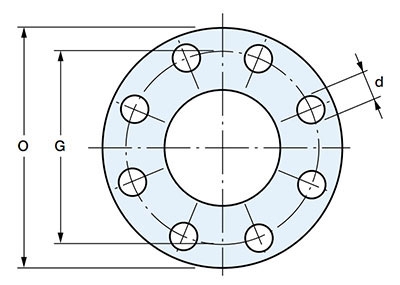
- O is the outer flange diameter;
- G is the center distance of the flange mounting holes;
- d is the diameter of the flange mounting holes
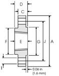
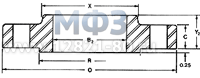
1. Flanges ANSI/ASME Slip On (Flange SO) - flat welded steel flanges.
Flat steel flanges are put on the pipe during installation and welded to it. DN: 1/2″-60″. Class: 150-1500, for 1500 lbs only 1/2″-2 1/2″ (ANSI B 16.5); 75-350 (ANSI B 16.47).
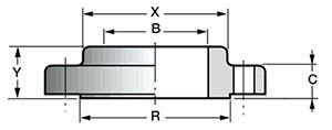
- Y is the height of the flange;
- C is the thickness of the body;
- B - inner flange diameter
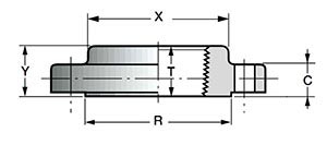
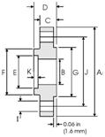
2. ANSI/ASME Threaded (Screwed, ST) Flanges - steel threaded flanges.
Threaded flanges are used with great restrictions in special cases. Their main advantage is the possibility of assembly without welding at high pressure in sections of pipelines where the use of welding is limited by safety standards. Threaded steel flanges cannot be used in conditions of strong temperature fluctuations and mechanical deformations, since there is a high probability of depressurization of the connection.
DN: 1/2″-3″.
Class: 150-1500, for 1500 lbs only 1/2″-2 1/2″ (ANSI B 16.5).
- Y is the height of the flange;
- C is the thickness of the body;
- R is the pressure surface diameter;
- X is the diameter of the joint for welding;
- T - thread length
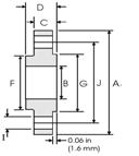
3. ANSI / ASME Welding Neck Flanges (WN, Weld Neck) - collar (steel welded butt) flanges.
Collar (skirt) flanges are butt-welded to the end of the pipe. This connection provides resistance to deformation, low and high temperatures, reduces turbulence in the area of the flange connection. Butt-welded steel flanges are most often used for pipelines with high loads.
DN: 1/2″-60″.
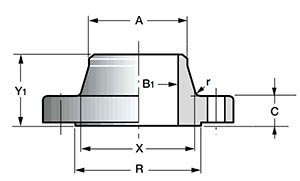
- Y 1 - flange height;
- C is the thickness of the body;
- R is the pressure surface diameter;
- X is the diameter of the collar for welding;
- B 1 - diameter of the inner flange;
- r - radius
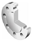
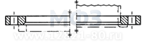
4. Flanges ANSI/ASME Lap Joint (LJ, Lapped Flange)
Slip-on flanges are similar in shape to flat slip-on flanges, but have a rounded inner lip near the sealing surface to fit snugly against the end weld ring. Flanges of this type are not welded to the pipe, but can rotate freely around it. Lap welded flanges are used in frequently dismantled sections of pipelines. These connections are easy to install because the mounting holes are easily aligned with the opposite flange. Loose flanges do not come into contact with the medium, so they do not have to be made of stainless steel.
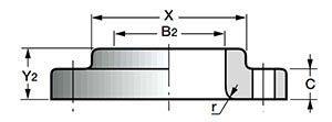
- DN: 1/2″-24″.
- Class: 150-1500, for 1500 lbs only 1/2″-2 1/2″ (ANSI B 16.5). Y 2 - flange height;
- C is the thickness of the body;
- X is the diameter of the joint for welding;
- B 2 - diameter of the inner flange;
- r - radius
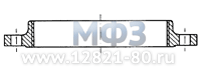
5. ANSI / ASME Socket Weld Flanges (SW) - flanges with a recess for welding (socket flanges).
Socket flanges (steel flanges with a recess for welding) are put on the end of the pipe and welded to it. The Socket weld flange is similar to a flat flange, but the hole radius of the welded face of the socket flange is larger than the inside radius of the pipe by about the thickness of its wall.
- DN: 1/2″-24″.
- Class: 150-1500, for 1500 lbs only 1/2″-2 1/2″ (ANSI B 16.5).Y - flange height;
- C is the thickness of the body;
- R is the pressure surface diameter;
- X is the diameter of the joint for welding;
- B is the groove diameter;
- B 3 - inner flange diameter
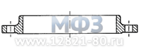
6. Flange ANSI/ASME Blind (Blank) - steel flange plugs.
Flanged steel plugs (steel welded flanges without a hole in the middle) are used to close the end section of the pipeline or to access its intermediate section.
DN: 1/2″-60″.
Class: 150-2500 (ANSI B 16.5); 75-900, 900 lbs only 26″-48″ (ANSI B 16.47).
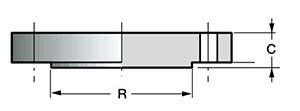
- C is the thickness of the body;
- R - pressure surface diameter
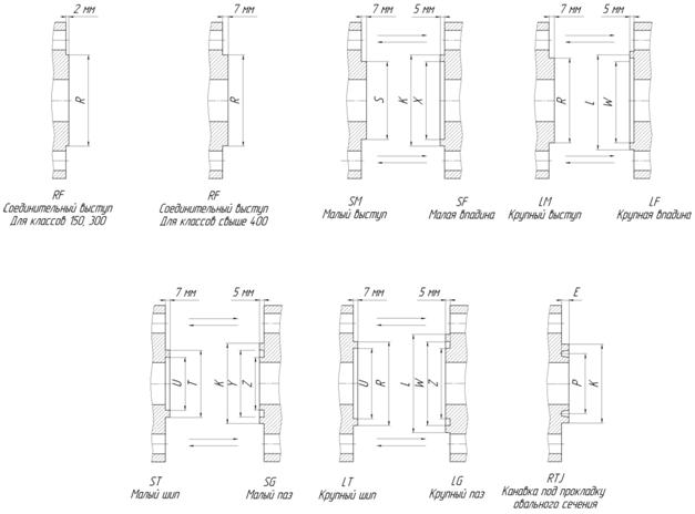
The ASME/ANSI standard specifies the following flange options.
| Scheme | Name |
|---|---|
 |
Raised face - Raised face for class 150 and 300 |
 |
Raised face - Raised face for class 400 and above |
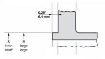 |
Large or small male face - Wide or narrow protrusion for class 300 and above |
 |
Large or small female face - Wide or narrow face for class 300 and above |
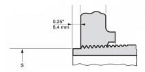 |
Small male face on end of pipe - Narrow ledge (end of pipe) for class 150 and above |
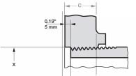 |
Small female face on end of pipe - Narrow cavity (end of pipe) for class 150 and above |
 |
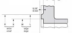
Large or small tongue face - Wide or narrow tongue for class 300 and above |
 |
Large or small groove face - Wide or narrow groove face for class 300 and above |
 |
Ring joint face - Octagonal or oval gasket for class 150 and above |
ASME B 16.5 FLANGES
The Steel Pipe Flanges and Flanged Fittings standard was published on June 16, 1977 as ANSI B16.5-1977 (American National Standards Institute - American national institute standards).
In 1982, the American National Standards Committee B16 was reorganized into the ASME Committee (The American Science of Mechanical Engineers), operating under ANSI accredited procedures.
After approval by the Standard Committee and ASME, ANSI approved on April 7, 1988 new edition as an American National Standard with the designation ASME/ANSI B16.5-1988 and on October 3, 1996, this edition was approved by ANSI as ASME B16.5-1988.
1. Welding Neck Flanges (WN)
They are butt welded to the end of a pipe and are typically used in harsh environments where high quality manufacturing is required. Since the inner diameter of the flange must match the inner diameter of the pipe, the flange hole diameter must be specified when ordering.
2. Through flanges Slip-On (SO)
This type of flange fits over the end of the pipe and is usually installed so that the face of the flange is 0.375 inches (9.5 mm) beyond the end of the pipe. This allows the flange to be welded on both sides - one weld is welded for strength to attach the flange stub to the pipe, and the seal weld is welded inside the flange at the end of the pipe. If the operating conditions allow, then the sealing weld is not made. Through flanges are most commonly used at lower pressures - class 150 (PN 20) or class 300 (PN 50) design pressure limits used.
Many pipe designers choose not to use through flanges for more high pressure due to the fact that:
a) The connection between the flange and the pipe is not as strong as when using weld neck flanges;
b) Such a flange-to-pipe connection is more prone to corrosion.
3.Threaded or threaded flanges Threaded flanges (TF)
Connects to the pipe like all other threaded fittings and can be welded to seal the flange to pipe connection. Available for most nominal diameters and pressure ratings.
4. Flanges welded with an overlap (free-rotating) Lap Joint (LJ) 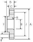
Are applied in the systems of pipes using connection of the cut-off ends of pipes with an overlap. They can be used for all pressure ratings and are available in all nominal diameters. Flanges of this type are put on the pipe, but are not welded or attached to it in any other way; the connection pressure is transferred to the seal via the flange pressure on the back of the lap joint.
Free-rotating flanges have a number of special advantages:
1. Free rotation around the pipe makes it easier to align the bolt holes of the opposite flange;
2. lack of contact with the liquid in the pipe often allows the use of low-cost carbon steel flanges in combination with corrosion-resistant pipes;
3. In systems that wear out or corrode quickly, the flanges can be remanufactured for reuse.
5. Socket-welding flanges (SW)
Features a notch at the back of the flange to connect to the end of the pipe, which is welded around the flange boss. Because weld-on joints are less strong than butt-weld joints, the use of this type of flange is almost completely limited by NPS (nominal pipe size), small nominal diameters, and low pressure ratings.
The main advantage of this type is the ease of preparation and installation.
6. Blind flanges (B)
Manufactured for all pressure ratings and nominal diameters, they are solid punchings used to seal the ends of a pipe system and provide easy access to the inside of the pipeline.
According to the shape of the contact surfaces, ASME flanges are divided into the following versions:
The most common American standard for steel flanges is ASME/ANSI B16.5 "Pipe Flanges and Flanged Fittings" (NPS 1/2 to NPS 24 pipe flanges and flanged fittings).
This standard, like domestic state standards, contains descriptions of standard sizes, approximate weights and tolerances for flanges DN ½ ″ ... 24 ″ (NPS, in inches) and Ru classes 150 ... 2500 (Class, in psi).
ASME/ANSI steel flanges, design and surface treatment
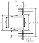
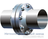
Steel Welding Neck Flange: API, ANSI/ASME flanges
Figure 1. Collar flange.
Weld Neck Flange ASME/ANSI, API
Flanges steel flat welded (Slip-on Flanges)
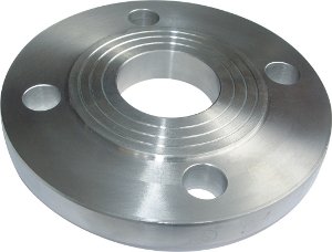
Figure 2. Flat flanges -
Slip On Flange ANSI/ASME
Flat flanges (slip-on flanges, literally translated as "snap-on flanges"), also standardized in most pressure classes and DN sizes, are popular due to their simplicity and application. This forged flange fits over the end of the pipe and is typically designed so that the flange extends over the end of the pipe by about 0.375" (9.5mm).
Flat flanges are used especially intensively for pipelines low pressures: Class 150 (PN 20) or Class 300 (PN 50).
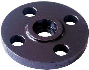
Threaded Flanges or Screwed Flanges
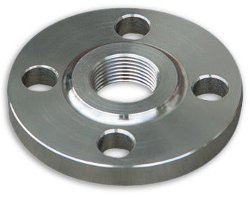
Figure 3. Threaded flange -
Threaded ANSI/ASME Flange
Threaded flanges (ASNE/ANSI nomenclature, Threaded or Screwed Flanges) are threaded to the pipe like other fittings with threaded connection. After screwing onto the pipe, such a flange can be welded to it to strengthen the connection.
Although ASME threaded flanges are standardized by US regulations for many pressure classes and nominal diameters, threaded flanges are used in exceptional cases of small diameters and low pressure classes.
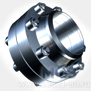
Loose flanges (Lap Joint Flanges, or Lapped Flanges, or Van Stone Flanges)
Loose flanges are used in frequently dismantled sections of pipelines.
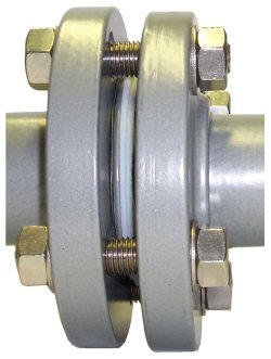
Figure 4 Loose flanges -
Lap Joint Flanges ASME/ANSI
Lap Joint Flanges are designed to tightly press the end weld ring or pipe collar. ASME/ANSI Lapped Flanges are free to rotate around the pipe when not connected.
ASME / ANSI Lap Joint flanges can be used in all pressure classes and are available in a full range of sizes. The pressure is transferred to the gasket by means of a flange and sealing surface welded ring.
Benefits of Lap Joint ANSI / ASME Flanges for Installation and Disassembly
Flanges have the following special advantages when mounting and dismounting:
- free rotation around the pipe makes it easy to align mounting holes for mounting bolts or opposing flanges;
- the lack of contact of the flange with the working medium in the pipe often allows the use of inexpensive carbon steel flanges with stainless pipes;
- loose flanges do not come into contact with the transported medium, therefore, it is possible to reuse ASME / ANSI flanges that have served even on pipelines that are highly susceptible to internal corrosion.
Socket flanges (ANSI/ASME Socket Weld Flanges)
|
Figure 5. Female flange - | ANSI/ASME Socket Weld Flanges are similar to flat flanges, but have a structural recess (nest) in the back of the flange, formed by a small collar. During installation, the end of the pipe is inserted and welded into the flange socket. However, a socket flange connection is not as strong as a butt weld flange connection, so this type of flange is always limited to NPS 4 (DN 100) and smaller sizes and has lower pressure tolerances. The advantage of ANSI / ASME female flanges is the ease of preparatory work and assembly of the flange connection. |
Blind Flanges ASME/ANSI
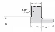
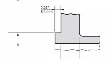
Raised flanges ANSI/ASME B16.5
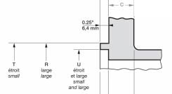
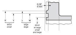
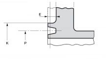
ANSI / ASME Class 150 (PN 20) and Class 300 (PN 50) flanges of all types, except loose flanges, typically have a 0.06" (1.6 mm) sealing rib (which is included in the thickness of the flange). ANSI flanges are over high pressures are equipped with a 0.25" (6.4 mm) protrusion in addition to the available flange thickness.
In such a case, these types of flanges can be fitted with a variety of other sealing surfaces such as lip and socket, tongue and groove, etc.
Loose flanges are made with a flat surface, as loose flanges do not have a sealing surface.
ASME/ANSI B 16.5 Class 150 (PN20) Flanges in ASTM-105 Forged Steel
As an example, here are the main features of ASME/ANSI B 16.5 forged flanges. The rows of the table with a white background represent the characteristics of the flanges in the American system of measurements (inches, pounds). Lines with a gray background give alternative values in SI units (millimeters, kilograms).
| NPS | Bolt holes | collar diameter | Approximate Weight (ANSI Flange Weight) | ||||||||
|---|---|---|---|---|---|---|---|---|---|---|---|
| DN | Number of holes | diam. bolt. resp. | diam. bolt. env. | nest depth | base | top | glad. rounded | ||||
| H | J | K | L | M | N | r | WN | SO, Threaded, SW | Blind | LJ | |
| ½ | 4 | 0.62 | 2.38 | 0.38 | 1.19 | 0.84 | 0.12 | 2 | 1 | 1 | 1 |
| 15 | 4 | 16 | 60.3 | 10 | 30.2 | 21.4 | 3 | 0.9 | 0.5 | 0.5 | 0.5 |
| ¾ | 4 | 0.62 | 2.75 | 0.44 | 1.50 | 1.05 | 0.12 | 2 | 2 | 2 | 2 |
| 20 | 4 | 16 | 69.8 | 11 | 38.1 | 26.6 | 3 | 0.9 | 0.9 | 0.9 | 0.9 |
| 1 | 4 | 0.62 | 3.12 | 0.50 | 1.94 | 1.32 | 0.12 | 3 | 2 | 2 | 2 |
| 25 | 4 | 16 | 79.4 | 13 | 49.2 | 33.5 | 3 | 1.4 | 0.9 | 0.9 | 0.9 |
| 1¼ | 4 | 0.62 | 3.50 | 0.56 | 2.31 | 1.66 | 0.19 | 3 | 3 | 3 | 3 |
| 32 | 4 | 16 | 88.9 | 14 | 58.7 | 42.1 | 5 | 1.4 | 1.4 | 1.4 | 1.4 |
| 1½ | 4 | 0.62 | 3.88 | 0.62 | 2.56 | 1.90 | 0.25 | 4 | 3 | 4 | 3 |
| 40 | 4 | 16 | 98.4 | 16 | 65.1 | 48.3 | 61 | 81 | 1.4 | 1.8 | 1.4 |
| 2 | 4 | 0.75 | 4.75 | 0.69 | 3.06 | 2.38 | 0.31 | 6 | 5 | 5 | 5 |
| 50 | 4 | 20 | 120.6 | 17 | 77.6 | 60.4 | 8 | 2.7 | 2.3 | 2.3 | 2.3 |
| 2½ | 4 | 0.75 | 5.50 | 0.75 | 3.56 | 2.88 | 0.31 | 8 | 7 | 7 | 7 |
| 65 | 4 | 20 | 139.7 | 19 | 90.5 | 73.0 | 8 | 3.6 | 3.2 | 3.2 | 3.2 |
| 3 | 4 | 0.75 | 6.00 | 0.81 | 4.25 | 3.50 | 0.38 | 10 | 8 | 9 | 8 |
| 80 | 4 | 20 | 152.4 | 21 | 107.9 | 88.9 | 10 | 4.5 | 3.6 | 4.1 | 3.6 |
| 3½ | 8 | 0.75 | 7.00 | - | 4.81 | 4.00 | 0.38 | 12 | 11 | 13 | 11 |
| 90 | 8 | 20 | 177.8 | - | 122.2 | 101.6 | 10 | 5.4 | 5.0 | 5.9 | 5.0 |
| 4 | 8 | 0.75 | 7.50 | - | 5.31 | 4.50 | 0.44 | 15 | 13 | 17 | 13 |
| 100 | 8 | 20 | 190.5 | - | 134.9 | 114.3 | 11 | 6.8 | 5.9 | 7.7 | 5.9 |
| 5 | 8 | 0.88 | 8.50 | - | 6.44 | 5.56 | 0.44 | 19 | 15 | 20 | 15 |
| 125 | 8 | 23 | 215.9 | - | 163.5 | 141.3 | 11 | 8.6 | 6.8 | 9.1 | 6.8 |
| 6 | 8 | 0.88 | 9.50 | - | 7.56 | 6.63 | 0.50 | 24 | 19 | 26 | 19 |
| 150 | 8 | 23 | 241.3 | - | 192.1 | 168.3 | 13 | 10.9 | 8.6 | 11 | 8.6 |
| 8 | 8 | 0.88 | 11.75 | - | 9.69 | 8.63 | 0.50 | 39 | 30 | 45 | 30 |
| 200 | 8 | 23 | 298.4 | - | 246.1 | 219.1 | 13 | 17.7 | 13.6 | 20.4 | 13.6 |
| 10 | 12 | 1.00 | 14.25 | - | 12.00 | 10.75 | 0.50 | 52 | 43 | 70 | 43 |
| 250 | 12 | 26 | 361.9 | - | 304.8 | 273.0 | 13 | 23.6 | 19.5 | 31.8 | 19.5 |
| 12 | 12 | 1.00 | 17.00 | - | 14.38 | 12.75 | 0.50 | 80 | 64 | 110 | 64 |
| 300 | 12 | 26 | 431.8 | - | 365.1 | 323.8 | 13 | 36.3 | 29.0 | 49.9 | 29.0 |
| 14 | 12 | 1.12 | 18.75 | - | 15.75 | 14.00 | 0.50 | 110 | 90 | 140 | 105 |
| 350 | 12 | 29 | 476.2 | - | 400.0 | 355.6 | 13 | 50.0 | 41.0 | 63.5 | 47.6 |
| 16 | 16 | 1.12 | 21.25 | - | 18.00 | 16.00 | 0.50 | 140 | 98 | 180 | 140 |
| 400 | 16 | 29 | 539.7 | - | 457.2 | 406.4 | 13 | 64.0 | 44 | 5.81 | 81.6 |
| 18 | 16 | 1.25 | 22.75 | - | 19.88 | 18.00 | 0.50 | 150 | 130 | 220 | 160 |
| 450 | 16 | 32 | 577.8 | - | 504.8 | 457.2 | 13 | 68.0 | 59.0 | 99.8 | 72.6 |
| 20 | 20 | 1.25 | 25.00 | - | 22.0 | 20.0 | 0.50 | 180 | 165 | 285 | 195 |
| 500 | 20 | 32 | 635.0 | - | 558.8 | 508.0 | 13 | 81.6 | 75.0 | 129.0 | 88.5 |
| 24 | 20 | 1.38 | 29.50 | - | 26.12 | 24.00 | 0.50 | 260 | 220 | 430 | 275 |
| 600 | 20 | 35 | 749.3 | - | 663.6 | 609.6 | 613 | 118 | 99.8 | 195.0 | 125.0 |
The following abbreviations are used in the header of the table:
- NPS - Flange DN in inches,
- DN - Flange DN in millimeters,
- H is the number of holes for fasteners;
- J - diameter of holes for fasteners;
- K is the diameter of the bolt circle;
- L is nest depth;
- M - the base of the collar of the collar and socket flanges, Weld Neck, Socket Weld Flange;
- N - welded end of the collar of the collar flange Flange Weld Neck;
- r is the radius of the Socket Weld Flange;
- WN- collar flanges ANSI B16.5 Weld Neck;
- SO - Slip On flat flanges;
- Threaded - Threaded flanges Screwed;
- SW - socket flanges, Socket Weld Flange;
- LJ - loose flanges, Lap Joint Flanges.
Conclusion
Studying foreign standards for flanges allows you to learn from the mistakes and successes of others. The experience of Engineering Union LLC, quality and stock makes it possible to fulfill regular customer orders with high quality, and maintain highly competitive ones.
Bibliography
- Yufin V. A. Pipeline transport of oil and gas .. - M .: Nedra, 1976.
- Flange type duct joint assembly: Pat. US4218079 USA F16L23/00.. - 1980.
By accessing this page, you automatically accept
We produce a wide range steel flanges: corrosion-resistant, stainless flanges, flanges made of carbon and alloy steels, cold-resistant and heat-resistant flanges, equal bore flanges and adapter flanges, flat flanges And collar flanges, according to Russian and foreign standards.
What is a flange
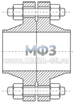
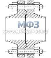
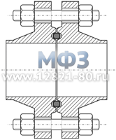
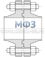
Flange- this is a metal disk that serves for mutual butt fastening of pipes, cylinders, seals, generally hollow (cylindrical and other shapes) objects, in particular cases also for mutual fastening of sheets (in boilers, tanks, etc.), and the flanges are narrower are not disc-shaped. In pipes, the steel flanges are for the most part left as they came out of the casting or the forge; occasionally, however, they are turned on lathe. When two objects are connected by flanges, circles of various soft materials are laid between the flanges. The flanges are pressed (during the deployment of the bolts) into these gasket circles, and thus the tightness of the joint is achieved. Rice. 1, 2 depict a flange connection of two steel pipes native flanges.
Encyclopedic Dictionary F.A. Brockhaus and I.A. Efron
In other words, the main advantage of using steel flanges is to ensure a hermetic collapsible connection of sections of pipelines, vessels, tanks, apparatuses, tanks containing or transporting substances in the liquid or gaseous phase. Flanges are not fasteners, but serve as a support for fasteners.
|
|
|

Standard steel flanges
Flanges according to domestic standards GOST, OST, ATK
Flanges of various Du
For flanges as for others piping parts, the Russian standard GOST 28338-89 sets a parametric series of 49 values nominal diameter(Dn, Dy, DN, nominal inner diameter of the pipeline), measured in mm. Flange DN- one of its main characteristics, but it is not an exact base flange size.
Flanges DN 15, 20, 25, 50, 80, 100, 200 are most often made of high-quality rolled metal by hot stamping. Medium bore flanges are manufactured from steel cast ring blanks. Large DN flanges (500, 600, 800, 1000, 1200, 1400, 1600, 1800, 2000, 2200, 2400, 2800, 3000, 3400, 4000 mm) can be made from forged blanks.
Flanges of various Ru
Another main flange parameter is conditional pressure(Ru, PN, kgf/cm², MPa) as the highest allowable overpressure at 20°C. The GOST 26349-84 standard defines a parametric range of 26 values from 0.1 to 800 kgf / cm².
DIN, EN flanges (European flanges)
We produce steel flanges according to European standards: flanges EN 1092-1(Euronorms, European Committee for Standardization), DIN flanges(Deutsches Institute fur Normung, German Institute for Standardization).
In many ways, EN 1092-1 is based on DIN standards. The following is a table of conformity between EN 1092-1 and DIN. The table shows the types of steel flanges according to EN 1092-1, the equivalent DIN standards for each nominal pressure are indicated. Flange types that are only described in EN 1092-1 but not described in DIN are marked with a "+". The sign "-" means that there is no standard for this pressure. The underlined standard numbers are taken from DIN.
| Types of steel flanges | EN type | Nominal pressure (PN) | |||||||||||
|---|---|---|---|---|---|---|---|---|---|---|---|---|---|
| 2,5 | 6 | 10 | 16 | 25 | 40 | 63 | 100 | 160 | 250 | 320 | 400 | ||
Plate flanges for welding(steel flat welded flange) | 01 | + | + | + | + | + | + | - | - | - | - | ||
|
02 | + | + | - | - | - | - | - | - | ||||
|
04 | - | - | - | - | - | - | - | - | ||||
|
11 | ||||||||||||
|
12 | - | + | + | + | + | + | - | - | - | - | ||
|
13 | - | + | + | - | - | - | - | |||||
| 05 | + | - | - | - | - | ||||||||
American Flanges ANSI/ASME B 16.5, ANSI/ASME B 16.47, API 6A
Nominal diameter of flanges (DN, DN, DN) according to American standards, it is measured in inches (1 ″ \u003d 2.54 cm). Value nominal pressure of flanges (Ru, PN) denoted by a number of classes (Class, pounds per square inch, lb/in², psi, pounds per squared inch): 150, 300, 400, 600, 900, 1500, 2000, 2500, 3000, 5000, 10000, 15000, 20000 .
| 1 psi = 0.00689476 MPa | 1 MPa = 10.19716213 kgf/cm² | 1 psi = 0.070306955 kgf/cm² |
| Pound-force per square inch (psi, pounds per squared inch, lbf/in², lb.p.sq.in.) | MPa | Technical atmosphere (at, at, kgf/cm², ati) |
|---|---|---|
| 150 | 1,03 | 10,55 |
| 300 | 2,07 | 21,09 |
| 400 | 2,76 | 28,12 |
| 600 | 4,14 | 42,18 |
| 900 | 6,21 | 63,28 |
| 1500 | 10,34 | 105,46 |
| 2000 | 13,79 | 140,61 |
| 3000 | 20,68 | 210,92 |
| 5000 | 34,47 | 351,53 |
| 10000 | 68,95 | 703,07 |
| 15000 | 103,42 | 1054,60 |
| 20000 | 137,90 | 1406,14 |
We make ANSI/ASME B16.5 flanges with nominal bore 1/2″ - 24″; large diameter flanges (26″ - 60″) are manufactured to meet the requirements ASME/ANSI B16.47. (ASME - American Society of Mechanical Engineers - American Society of Mechanical Engineers, ANSI - American National Standards Institute - American National Standards Institute). For high pressure classes (pressure class ≥ 2000 lbs) up to 20000 in the petrochemical industry, API 6A flanges(API - American Petroleum Institute, American Petroleum Institute). API 6A flanges are similar in size to ANSI B 16.5 but differ in materials of construction and cannot be joined together without being subjected to full working pressure. Threaded API flanges have a collar height greater than ASME B 16.5 flanges. The following table compares steel flanges ANSI/ASME B 16.5 And flanges API 6 A.
| Flange type | pressure class | Conditional pass | Old values conditional passes API |
|||
|---|---|---|---|---|---|---|
| ASME | API | ASME | API | |||
| Welding Neck (collar flanges) | 600 | 2000 | 2″ - 10″ | 2 1/16 — 11 | 1 1/2 — 10 | |
| 900 | 3000 | 2″ - 10″ | 2 1/16 — 11 | 1 1/2 — 10 | ||
| 1500 | 5000 | 2″ - 10″ | 2 1/16 — 11 | 1 1/2 — 10 | ||
| Threaded and integral flages (threaded flanges, welding flanges) | 900 | 3000 | 2″ - 20″ | 2 1/16 — 20 3/4 | 1 1/2 — 20 | |
| 1500 | 5000 | 2″ - 10″ | 2 1/16 — 11 | 1 1/2 — 10 | ||
Suggested nomenclature ANSI/ASME flanges, API (Flange designs).
We produce according to the customer's drawing steel flanges with an extended welded part (flanges with an extended collar, a long welded flange with a shoulder) (Long Weld Neck Flanges) and a sealing surface according to American standards. Flanges of this type are used for openings of vessels, reservoirs, heat exchange equipment, etc.
Versions of the sealing surface of steel flanges
Flange versions according to GOST and ATK
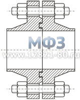
Sealing surface of steel flanges- the contact surface of the two flanges that make up the flange connection. Flanges in a flange joint must have matching sealing surfaces. For the main so-called straight flange, having a groove for a gasket, the opposite flange with a ledge is called counter flange(counter flange, companion flange, mating flange), since the shape of its sealing surface corresponds to the shape of the contact surface of the first flange. In various flange connections, steel flanges with sealing surface designs according to GOST 12815-80. Below are sections of flange connections with different types of sealing surfaces.
|
|
|
|
|
|
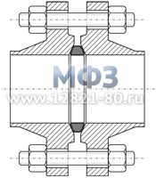
For greater tightness, flange connections with steel gaskets and lenses. Round steel gaskets of octagonal section are used for flanges in accordance with GOST 28759.4-90 and OST 26-842-73. These steel seals provide more effective sealing of the flange joint than oval gaskets, however, oval gaskets are more versatile in application: they can also be used for octagonal gasket grooves.
Flange face types DIN, EN
The European standards DIN and EN 1092-1 require the production of steel flanges with sealing surfaces ( flange facing types) presented in the following table. The sealing surfaces of the EN 1092-1 flanges for low PN are made with a roughness of Ra=3.2…12.5 µm, for high PN, processing with a roughness of Ra=0.8…3.2 µm is used (such designs are underlined in the table).
| Type of sealing surface | Description according to DIN 2526 | Design according to EN 1092-1 | |
|---|---|---|---|
| Standards | Version (Type) | ||
|
DIN 2641/2642 |
||
DIN 2527 |
|||
|
DIN 2630, 2631, 2632, 2633, 2634, 2635 |
Type C |
Type B1 (main application for PN 2.5 - PN 40) |
Type B2(main application for PN 63 - PN 100) |
|||
|
DIN 2512 (PN 10 - PN 160) |
||
|
DIN 2512 (PN 10 - PN 160) |
||
|
DIN 2513 (PN 10 - PN 100) |
||
|
DIN 2513 (PN 10 - PN 100) |
||
|
DIN 2514 (PN 10 - PN 40) |
||
|
DIN 2514 (PN 10 - PN 40) |
||
|
DIN 2696 (PN 63 - PN 400) |
||
|
DIN 2695 (PN 63 - PN 400) |
||
Flange face designs ANSI, ASME, API
API 6A flange sealing surfaces comply with API 6B (for R oval, R octagonal, RX gaskets) and API 6BX (for BX steel gaskets).
| Type of sealing surface | Application conditions | |
|---|---|---|
| Name | Drawing | |
| Raised Face Flange (steel flange with connecting ledge) |  |
Class 150, 300 (PN 20 - 50) |
 |
Class ≥ 400 (PN ≥ 68) |
|
| Male Flange(steel flange with a ledge, colloquial "daddy") |  |
Class ≥ 300 (PN ≥ 50) |
| female flange(steel flange with a hollow, colloquial "mother") |  |
Class ≥ 300 (PN ≥ 50) |
| Small Male Flange(steel threaded flange with ledge) |  |
Class ≥ 150 (PN ≥ 20) |
| Small Female Flange(steel threaded flange with a hollow) | 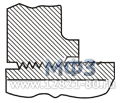 |
Class ≥ 150 (PN ≥ 20) |
| Tongue Flange(flange with steel spike) |  |
Class ≥ 300 (PN ≥ 50) |
| Groove flange(flange with steel groove) | 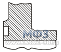 |
Class ≥ 300 (PN ≥ 50) |
| Ring Joint Flange (RJ)(flange for round steel gasket) | 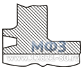 |
ASME B16.5 Flanges Class ≥ 150 (PN ≥ 20) |
API 6B Flanges (Type R ring joint: oval, octagonal) Class 5000 - 10000 (PN 345 - 690) |
||
API 6B Flanges (Type RX ring joint) Class 5000 - 10000 (PN 345 - 690) |
||
API 6BX Flanges (Type BX ring joint) Class 5000 - 20000 (PN 345 - 1380) |
||
Flanges steel special to order
Let's make special flanges (non-standard), such as: high pressure flanges (flanges with a thorn-groove sealing surface for a pressure of 250-300 kg / cm²; mating flanges; flanges to order; flanges for special equipment, flanges for connecting pipeline sections of various standards, flanges for pipe valves, adapter flanges, as well as gas flanges; flanges according to the drawings (the drawing is agreed by the customer).
Our factory is ready to produce flanges with sealing surfaces according to foreign standards ANSI, ASME, API, DIN, EN: flanges for Ring Joint Gaskets types RX, BX, R Octagonal, R Oval, flanges for lens seal, flanges for gaskets of oval and octagonal section . We will complete the reinforcement flanges with sealing gaskets and fasteners.
Choice of steel for flanges
Flanges for pipelines with low performance requirements are made of the following steels:
- 20FA - 20FA flanges;
- 3, 20 (ASTM A 105 Gr1, A 106 GrA, B, A 659 CS Type 1020, A 794 CS Type 1020, EN 1.1151, AISI 1020, DIN C22E) - carbon steel flanges.
Cold-resistant flanges with easy weldability made of steel 09G2S (ASTM A 516-65, A 561 Gr70, A 516-55, A 516-60) (structural low alloy for welded structures) - flanges for cryogenic temperatures and harsh winter climatic conditions.
Heat-resistant flanges subject to high temperatures of the external and internal environment are made of steels:
- 10X11H23T3MR - heat-resistant flanges made of high-alloy steel;
- 15X5M (American counterparts: A 193 Grade B5, A 182 Grade F5) - heat-resistant flanges made of low-alloy martensitic steel;
- 13HFA.
We offer flanges made of corrosion-resistant steels. Flanges made of these steel grades can be used at chemical facilities:
- 10X17H13M2T (UNS S31635, AISI 318, 316H, 316Ti, DIN EN X10CrNiMoNb18-12, 1.4583, 1.4571, X10CrNiMoTi18-12, X10CrNiMoTi18-10, X6CrNiMoTi17-12-2) — heat-resistant stainless steel flanges;
- 08X18H10T (AISI 321, UNS S32100, DIN EN 1.4878, 1.4541, X6CrNiTi18-10, X12CrNiTi18-9, X10CrNiTi18-9) - heat-resistant stainless steel flanges;
- 10X17H13M3T (UNS S31635, DIN X10CrNiMoTi18-12, 1.4573, GX3CrNiMoCuN24-6-5, AISI 316Ti) - heat resistant stainless flanges;
- 10X11H23T3MR - stainless steel heat-resistant flanges;
- 12X18H10T (AISI 321) - austenitic steel flanges, stainless cryogenic flanges for operation in dilute solutions of acetic, phosphoric, nitric acids, salt and alkali solutions at temperatures from -196 to +600 ° C under pressure, flanges with unlimited weldability;
- 06ХН28МДТ (DIN 1.4563, UNS N08028) - heat-resistant stainless steel flanges;
- 14X17H2 (AISI 431, DIN X20CrNi72, X22CrNi17) - stainless steel heat-resistant flanges;
- 20X13 (AISI 420, ASTM A 580 420, A 276 420) - stainless steel heat resistant flanges.
Thus, the use of steels of various grades gives us the opportunity to produce flange connections for different operating conditions: flange connections for chemically active media, for high-pressure pipelines, for high and low operating temperatures.
Manufacture of flanges from various blanks
The technological capabilities of our company allow us to produce flanges and other rotating parts with DN from 200 to 3000 mm (Dn flanges, Dn up to 3000) weighing up to 7 tons.
Cast flanges
Our centrifugal electroslag casting machine ensures high quality of cast metal by electroslag refining. Fur. At the same time, the properties of blanks do not lose to forged ones in strength, but surpass them in terms of impact strength and ductility.
Forged blank flange
Steel blanks for flanges can be obtained by hot stamping technology. An important advantage of this production method is the low price of the flanges and the short turnaround time of the flanges.
Manufacture of flanges from forgings
Let's make collar flanges, flanges of vessels and devices, flanges of big conditional passes from forgings. Forged flanges are manufactured on request.
Flange quality control
We carry out the following points for controlling the properties of flanges:
- macro- and microstructure;
- geometric control;
- incoming, outgoing control chemical composition;
- mechanical properties of steel (properties).
We will complete the shut-off and control pipeline fittings with flanges
Connecting valve flanges must be attached to reciprocal welded flanges pipes. The Hardware and Flange Plant company completes flange gate valves, valves, dampers, taps, gates and other pipeline equipment standard and special flanges.
We complete with flanges valves, pipe shut-off and control fittings various types and locking and regulating butterfly valves. We complete valves with flanges:
- control valves;
- control valves, throttle and shut-off;
- combined non-return and shut-off valves.
And also we will complete with flanges rotary return dampers of RZI and RZN types with Dn from 500 to 3000 mm, pressures Pn 2.5, 6, 10, 16, 25, 40, pressure classes ANSI 150, 300, operated in the temperature range from -50 C to + 200 °C.
Let's make flanges for critical knots and pipelines. We will produce components and assemble the flange assembly according to assembly drawings.


