In accordance with GOST 24856-2014. Pipeline fittings. Terms and definitions “a flange is a fitting element used to connect it to a pipeline or technological equipment. In most cases, flanges are made in the form of a flat ring with a sealing surface and holes for fasteners.
The same regulatory document talks about the main types of flanges: flat flange, butt weld flange (collar), threaded flange.
Flange fittings
Equipped with flanges pipeline accessories is called flanged fittings, and the pipe that provides a flanged connection to the pipeline is called a flanged pipe.
Despite the fact that each of the methods of connecting pipeline fittings tends to have its most preferable combination of conditions (nominal parameters of the fittings, materials from which it is made, properties of the working environment, etc.), “areas of interest” different types connections may overlap. In this case, there is a reason to talk about technological competition between various connections of pipeline fittings. For example, during the design and construction pipeline systems for transportation of liquefied natural gas(LNG) flanged fittings are directly “opposed” by welded fittings.
Like any other, flange connection of fittings, along with undoubted advantages, does not have the most strengths. But in the case of flanged fittings, the balance between them is still more often in favor of the “pluses”, and it is flanged connections that pipeline system designers choose. This is clearly confirmed by the high specific gravity of flanged fittings among other types of fittings for connecting to a pipeline.
Flange connection tightness
The most important requirement for any connection of pipeline fittings is tightness. Depressurization flange connections occurs not due to their inherent objective shortcomings, but due to purely subjective factors ─ untimely or insufficient service. To ensure that the seal is maintained high level, it is necessary to periodically tighten the fasteners securing the flange connection. And, of course, do not forget to change the gaskets between the flanges.
The advantages of a flange connection are strength, reliability, the possibility of repeated installation and dismantling and use in a wide temperature range. Flanges can handle virtually any diameter of fittings, which is convincingly proven by the experience of leading domestic and foreign manufacturers. For example, the ARmatek company from St. Petersburg supplies counter flanges for pipeline fittings with a diameter of 10 to 1800 millimeters.

Flanges and GOST
The impressive variety of flanges does not turn into chaos, on the contrary, it is structured and orderly. The designs, design options, standard sizes of flanges, as well as general technical requirements for them, the materials used for their manufacture, and methods of fastening have been standardized.
Currently, the national standard of the Russian Federation “GOST R 54432-2011” is in force. Flanges of fittings, connecting parts and pipelines for nominal pressure from PN 1 to PN 200. Design, dimensions and general technical requirements.” Its validity period is limited. It is ready to be replaced by GOST 33259-2015. Flanges of fittings, connecting parts and pipelines for rated pressure up to PN 250. Design, dimensions and general technical requirements.” This follows from Rosstandart Order No. 443-st dated May 26, 2015, which contains a reference to the protocol dated March 27, 2015 No. 76-P of the meeting of the Interstate Council for Standardization, Metrology and Certification. The new GOST will be put into effect for voluntary use from April 1, 2016. After this, eight GOSTs that have already become familiar will cease to be in force:
- GOST 12815-80. Flanges of fittings, connecting parts and pipelines for Py from 0.1 to 20.0 MPa (from 1 to 200 kgf/cm2). Types. Connecting dimensions and dimensions of sealing surfaces;
- GOST 12816-80. Flanges of fittings, connecting parts and pipelines for Py from 0.1 to 20.0 MPa (from 1 to 200 kgf/cm2). General technical requirements;
- GOST 12817-80. Flanges cast from gray cast iron to Ru from 0.1 to 1.6 MPa (from 1 to 16 kgf/cm2). Design and dimensions;
- GOST 12818-80. Flanges cast from malleable cast iron to Ru from 1.6 to 4.0 MPa (from 16 to 40 kgf/cm2). Design and dimensions;
- GOST 12819-80. Cast steel flanges for Ru from 1.6 to 20.0 MPa (from 16 to 200 kgf/cm2). Design and dimensions;
- GOST 12820-80. Steel flat welded flanges for P from 0.1 to 2.5 MPa (from 1 to 25 kgf/cm2). Design and dimensions;
- GOST 12821-80. Steel flanges butt welded to P from 0.1 to 20.0 MPa (from 1 to 200 kgf/cm2). Design and dimensions;
- GOST 12822-80. Loose steel flanges on a welded ring for Ru from 0.1 to 2.5 MPa (from 1 to 25 kgf/cm2). Design and dimensions.
Flange types
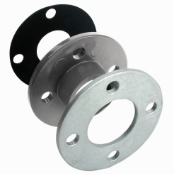
GOST 33259-2015 identifies six types of flanges. The names of the first four begin the same ─ with the words “flat steel flange”. This is type 01 ─ steel flat flange welded, type 02 ─ steel flat flange free on a welded ring, type 03 ─ steel flat flange free on a flange, type 04 ─ steel flat flange free on a welding clamp. The rest are ─ type 11 ─ steel butt weld flange and type 21 ─ valve body flange, i.e. when the flange is part of the valve body. The flanges of the valve body can be cast steel or cast iron - gray or ductile.
Flat welded steel flanges are “strung” onto the pipe and welded directly to it.
The peculiarity of loose flanges is that the diameter of their internal hole is larger than the outer diameter of the pipe, and they can easily be rotated on the pipe, which greatly facilitates installation.
A steel flat flange free on a welded ring, in addition to the flange itself, includes a ring that matches the flange in terms of nominal diameter. By welding, only the ring is fixed, while the flange itself remains free. This is useful when installing flange connections in inconvenient or hard-to-reach places, as well as when they need to be frequently dismantled and repaired.
To use steel flat flanges free on the flange, preparation of the end of the pipe is necessary. It is modified to form a flat thrust surface. Such flanges are optimal for pipelines made of non-ferrous metals.
When installing steel flat flanges free on a welding clamp, a clamp is used instead of a closed ring.
A steel butt weld flange is attached with one weld, connecting the butt end of the pipe and the “collar” of the flange (that’s why such flanges are called collar flanges). Inner diameter collar flange equal to the diameter of the pipe.
In accordance with GOST 33259-2015, there are two ranges of sizes for types 01, 02, 11 and 21. Row 1 is preferred.
Sealing surface design
The most important design parameter of any flange is the design of the sealing surface. In accordance with GOST 33259-2015, which comes into force on April 1, 2016, ten designs have been adopted with a detailed indication of their dimensions:
- version A ─ flat;
- version B ─ connecting protrusion (corresponds to version 1 hereinafter ─ in accordance with GOST 12815-80);
- version C, L ─ tenon (corresponds to versions 4 and 8);
- version D, M ─ groove (corresponds to versions 5 and 9);
- version E ─ protrusion (corresponds to version 2);
- version F ─ cavity (corresponds to version 3);
- version J ─ for oval gasket (corresponds to version 7);
- version K ─ for lens gasket (corresponds to versions 6 and 8).
Versions C, L and E may only be used upon customer request.
Of all the flange shapes...
...round is optimal. Flanges of other shapes are much less common.
Although the standards allow the production of square flanges of all designs with the exception of flanges of size range 2, which have four holes for studs (bolts) for a nominal pressure of no more than PN 40.
By the way, threading is allowed in the flange holes for fasteners.
Materials and technology for manufacturing flanges
For the manufacture of steel and cast iron flanges the following are used:
- steel ─ carbon, low-alloy, heat-resistant, corrosion-resistant;
- casting ─ from alloyed, high-alloyed and unalloyed steel;
- gray cast iron ─ SCh 15, SCh 20;
- malleable cast iron ─ CN 30-6;
- high-strength cast iron ─ HF 40, HF 45.
The manufacturing technology of flanges must ensure strict compliance with their geometric dimensions and mechanical properties.
Flanges of types 01, 02, 03, 04 can be made from sheet metal. Provided that the welds are made with full penetration over the entire cross-section, these types of flanges can be made welded. Type 11 flanges (butt-welded steel) are not allowed to be made from rolled sheets. They are made from forgings or stamped blanks.
Flanges made by hot metal forming - forging, rolling, stamping - meet modern operating requirements to the fullest extent possible. Particularly good results are achieved by producing flanges using hot stamping and subsequent heat treatment. Hot-stamped forgings are currently the main type of blanks for pipeline valve flanges. This technology is especially relevant in the manufacture of steel butt-welded flanges.
Being less susceptible to deformation, cast iron flanges retain their shape better than steel flanges, but require more careful handling, given their relative fragility. Thus, tightening flange connections of cast iron fittings must be done with care so that excessive zeal does not lead to a break in the flange.
Fasteners
The role of fasteners in flange connections cannot be underestimated. Bolts or studs have to “take the hit” mechanical loads trying to break the connection. Fasteners (bolts, studs, nuts) are usually made of the same or similar material properties as the flanges themselves. By avoiding significant differences in linear expansion coefficients, it is possible to ensure synchronism in the response of the flange and fasteners to temperature changes, which is important during operation.
Holes for fasteners in the flanges of pipeline fittings must be located symmetrically with respect to both vertical and horizontal main axes. But not on themselves.
To save time spent on selection and reduce the cost of delivery of the necessary fasteners, it is convenient to order it complete with flanges from one company. This will also serve as a guarantee of their full compatibility. This opportunity is available to customers who contact ARMATEK. It will also help to equip flanges with wafer gaskets made of various materials. After all, the tightness of the flange connection largely depends on their properties and qualities.
Flange gaskets
The material of the gasket must correspond to the conditions of its operation, taking into account the parameters (pressure, composition, temperature) of the working and environmental conditions.
Movable or fixed sealing of flange connectors provides various materials: rubber, paronite, fusible sealant, etc. Flat flanges are sealed using soft metal or corrugated gaskets with soft padding.
For flange versions A, B, C, D, E and F, it is permissible to use a wide range of gaskets: metal (including gear), metal-graphite based on thermally expanding graphite (TEG), spiral-wound (SNP), elastic (they are especially are in demand for cast iron flanges). If we are talking about hazardous substances of hazard classes 1, 2 or 3 or fire and explosive substances, for flanges with sealing surfaces A and B, wave gaskets TRG with an elastic secondary seal should be used, and gaskets SNP should be equipped with two restrictive rings.
Flanges with sealing surfaces, versions K and J, are used with lens gaskets, as well as oval and octagonal gaskets. And flanges with sealing surfaces of versions L and M ─ with gaskets based on fluoroplastic-4.
An important parameter of a flange connection of pipeline fittings is the compression force of the gasket, the value of which is measured in hundreds of kN.
The dimensions of the gasket should ensure the assembly of the flange connection, taking into account the dimensions of the versions of the sealing surfaces of the flanges, and the design should ensure centering of the gasket during assembly, preventing the possibility of extrusion. Better fixation of the gasket can be provided by individual elements of the flange structure. For example, the groove for the gasket and the tenon in the mating flange form a kind of lock that protects the gasket and thereby increases the reliability of the connection.
Flange designation
For convenience and the possibility of comparison, the “old” and “new” marking order is summarized in a small table.
|
Steel flat welded flanges |
Flange X1-X2-X3-X4 GOST 12820-80, where: X2 ─ nominal diameter; X3 ─ nominal pressure; X4 ─ grade of material. |
Flange X1-X2-X3-X4-X5-X6-X7 GOST 33259 X1 ─ nominal diameter X2 ─ nominal pressure X3 ─ flange type number X6 ─ grade of material X7─ control group |
|
Butt welded steel flanges |
Flange X1-X2-X3-X4 GOST 12821-80 X1 ─ design of the sealing surface according to GOST 1285-80 X2 ─ nominal diameter X3 ─ nominal pressure X4 ─ grade of material |
|
|
Flat steel flanges free on a welded ring |
Flange X1-X2-X3 GOST 12822-80 X1 ─ nominal diameter X2 ─ nominal pressure X3 ─ grade of material Ring X1-X2-X3-X4 GOST 12822-80 X1 ─ design of the sealing surface according to GOST 1285-80 X2 ─ nominal diameter X3 ─ nominal pressure X4 ─ grade of material |
Flange X1-X2-X3-X4-X5-X6 GOST 33259 X1 ─ nominal diameter X2 ─ nominal pressure X3 ─ flange type number X4 ─ size range number (1 or 2) X5 ─ grade of material X6 ─ control group Ring X1-X2-X3-X4-X5-X6-X7 GOST 33259 X1 ─ nominal diameter X2 ─ nominal pressure X3 ─ flange type number X4 ─ size range number (1 or 2) X5 ─ sealing surface design X6 ─ grade of material X7─ control group |
The changes can be compared using several specific examples.
|
Designation according to GOST 12820-80-GOST 12822-80 |
Designation according to GOST 33259-2015 |
|
Flange 1-50-10 St 25 GOST 12820-80 |
Flange 50-10-01-1-V-St 25-III GOST 33259 |
|
Flange 9-50-10F St 25 GOST 12821-80 |
Flange 50-10-01-1-M-St 25-IV GOST 33259 |
|
Flange 3-50-100 St 25 GOST 12821-80 |
Flange 50-100-11-1-F-St 25-IV GOST 33259 |
|
Flange 5-50-100 St 25 GOST 12821-80 |
Flange 50-100-11-1-D-St 25-IV GOST 33259 |
|
Flange 50-10 St 25 GOST 12822-80 Ring 5-50-10F GOST 12822-80 |
Flange 50-10-02-1-St 25-IV GOST 33259 Ring 50-10-02-1-L-St 25-IV GOST 33259 |
Flange fittings occupy an important place among other types of fittings for connecting to a pipeline, and flanges various types and sizes continue to be an extremely common element of a huge number technological systems, one of the most common methods of installing pipeline fittings.
Preload (tightening) necessary to ensure tightness sealing flange connection in working conditions.
For sealing pipeline components high pressure, mainly used , manufactured according to .
Widespread use of shutters with these fasteners contributed to the following: simplicity and manufacturability in manufacturing; reliable calculation and design methods; long-term traditions of designing and manufacturing SVD. The disadvantages of these valves are the high labor intensity of the bulkheads associated with the duration of screwing the connected threaded parts, as well as the difficulty of mechanizing and automating the process of assembling and disassembling the valve due to large number hairpins The desire to reduce the labor intensity of the bulkhead process and its mechanization has led to the creation of a wide variety of designs of special devices for preloading (tightening) studs or bolts and nuts.
Tightening fasteners by applying torque
The main advantages of the torque fastening method are its versatility, simplicity and high performance. Disadvantages - rather low efficiency (only 10% of the total spent on tightening threaded connection work accounts for the creation of axial force) and the occurrence of torsional stresses in the stud during tightening, which reduce .
When tightening the connection, the torque M kr applied to the nut is spent to overcome the friction of the nut end against a stationary supporting surface and friction of the contacting surfaces of the thread of the nut and stud:
M cr = M t + M p, (1)
Where M t is the moment of friction of the end of the nut on the stationary supporting surface of the parts being connected; M p - torque in the thread;
M t = f T Q 3 R T, (2)
Where f T is the coefficient of friction at the end of the nut; Q 3 - tightening force; R T - conditional friction radius of the nut;
R T = (1/3)(D G 3 - d shb 3) / (D G 2 - d shb 2), (3)
where DT is the diameter of the outer supporting surface of the nut; d shb - internal diameter . Torque in thread
M p = Q 3 (P/ 2π + f p d 2 / 2), (4)
Where R— thread pitch; f p is the coefficient of friction in the thread; d 2 - average thread diameter. For threaded connections when the contacting surfaces are lubricated with industrial oil and there are no electrolytic coatings on them f T = 0.12, f p = 0.20.
Tightening fasteners by applying axial forces to the shank of a bolt or stud
The method of tightening threaded connections by applying axial forces to the stud rod is free from the disadvantages of the considered method. The method consists of stretching the stud rod with a special device (hydraulic jack), followed by loosely screwing the nut to fix the stud rod in a stretched state.
The peculiarity of the method is that after tightening the nut without applying torque, the connection elements remain unloaded: the connection thread stud - nut and micro-irregularities of interfaces nut - washer And . As a result, after removing the tensile load on the stud, these elements are loaded and deformed, as a result of which the residual tightening force decreases.
Measuring the degree of force reduction in a stud using the unloading factor
Force reduction degree in high heels appreciate unloading factor. The stud unloading coefficient takes into account the reduction in force in the studs when the load is transferred to the main nut after the load of the loading device is removed and is equal to the ratio of the force stretching the stud to the residual force in it.
Sequence of tightening fasteners in a flange connection
Due to the fact that when tightening practically only one or several studs (group of studs) are loaded at the same time, then it is necessary to observe a certain sequence when tightening each stud or individual groups of simultaneously tightened studs. Compliance with a certain sequence when tightening the studs is due to the peculiarities of tightening a group threaded connection, which are as follows. Tightening on high pressure pipelines leads to axial displacement of the sealing surface of the flange or plug due to a decrease in the linear dimensions of the sealing ring in the axial-radial direction, deformation of microroughnesses of the contacting surfaces, compression of the materials of the flange of the vessel body and lid in the area of the sealing surfaces and other deformations. As a result of these deformations, an axial movement of the cover plane occurs, on which the nuts of the main fasteners rest.
Consistently reducing the tightening force of flange fasteners
Loading modes of flange connection studs
The loading modes of flange connection studs are divided into
- one-time and
- group.
One-time tightening mode for flange fasteners
The fastest, most reliable and ideal from the point of view of ensuring accuracy and uniformity of loading is method of tightening all studs at once connections. In this case, all connection studs are loaded simultaneously with forces of equal current values.
Group methods for tightening studs or bolts of flange connections
If it is impossible to create a one-time loading mode, group modes are used. In group tightening mode, all valve studs are divided into groups of simultaneously tightened studs. Groups of studs must be evenly distributed along the perimeter of the bolt circle. Number of studs in a group there must be multiple of the total number of studs flange connection.
Group tightening mode can be
- single-bypass and
- multi-bypass.
Group single-pass mode for tightening fasteners of a flange connection
At single-bypass mode the load is applied sequentially to each group of simultaneously tightened studs only once. In this case, the load on the studs of each group changes from the maximum (for the first group) to the design tightening force (for last group). The advantage of this tightening mode: relatively short duration the process of tightening the studs, as well as more high accuracy loading (compared to multi-bypass mode), due to the large number of bypasses and associated loading errors. The main disadvantage is the relatively high loading force of the studs of the first group compared to the loading force of the last group (often differing by 8-10 times).
In connection with these disadvantages, obstacles to using the single-bypass tightening mode may be:
- insufficient loading device power;
- insufficient stud mounting shank strength, which must correspond to the loading force of the studs of the first group.
Group multi-pass mode for tightening flange studs with nuts
In this case, use multi-pass group tightening mode. This mode consists of carrying out several loading rounds that follow one after another studs of all connection groups. The loading force of the studs during these bypasses depends on the adopted version of the multi-bypass tightening mode. The most common variant of the multi-bypass tightening mode is bypass-equalization.
Calculation of tightening modes for flange studs and nuts
Calculation of stud tightening modes. The one-time stud tightening mode is a special case of the single-round group tightening mode, in which the number of stud groups n=1, i.e. All flange studs are loaded simultaneously. In the single-pass mode of tightening the studs, the current loading force of the next group of studs (RD26-01-122-89)
Where K z 1 - unloading coefficient of studs of the corresponding group; Q n is the final tightening force of the studs of the last group; n = m/i—number of groups of pins in the gate; m- number of pins in the gate; i— number of simultaneously operating loading devices (hydraulic jacks); z— serial number of the loaded group of shutter plates. Ultimate Power Q n per group of studs at the end of the tightening process,
Q n = Q 3 / n,(6)
Where Q 3 - total tightening force of all bolt studs.
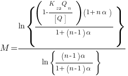
Relative compliance coefficient of the sealing gasket
α =λ 0 / λ Ш ( Q), (7)
λ 0 and λ Ш ( Q) - axial compliance of the sealing gasket and group of studs. Current value of the loading force of one stud of the corresponding group
Q z = Q z/ i. (8)
Current value of the loading force of one stud of the first group Q" z=1 is compared with the permissible load on one stud [ Q"]; the condition must be met
Q" z=1 ≤ [ Q"] (9)
Permissible load on one stud [ Q"] is taken equal to the smaller of two values:
1. from the condition of ensuring the strength of the mounting area of the stud thread
[Q"] ≤ 0,8 σ 20 Tsh F Sh, (10)
Where σ 20 ТШ - yield strength of the stud material at a temperature of 20°C; FШ - cross-sectional area of the mounting section of the stud;
2. or by the working force of the loading device (hydraulic jack)
[Q"] ≤ Q Well. . (eleven)
If condition (9) is not met, then it is necessary to calculate the bypass-equalizing mode of tightening the studs, and the current value of the loading force of the next group of studs with the corresponding bypass
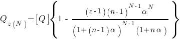 , (12)
[Q] = i[Q"]. (13)
Required number of rounds
 (14)
(14)
Where K z2 is the unloading coefficient of the studs during the bypass-equalizing tightening mode.
Stud relief factor for flange connections
Difference in the unloading coefficient of flange fasteners for sealing gaskets of different sections
Maximum coefficient values TO n unloading of studs in a single-pass tightening mode (the first group of fasteners) for an O-ring of the corresponding type are given in the table below.
| Section view of the steel gasket | Maximum value K n | |
| double cone gasket | 1,4 | |
| triangular gasket | 1,45 | |
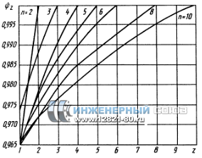
| Rice. 1. Dependence of coefficient ψ
z from WITH increasing load axial compliance flange parts decrease, and therefore the coefficient of unloading of the studs also decreases. In this regard, the stud unloading coefficients different groups connections are different. For the first group of studs, which is loaded with maximum load, the unloading coefficient is minimal; for the last group of studs the unloading coefficient is maximum. Unloading coefficient for a group of studs of the corresponding serial number K z = ψ z TO n, (15) Where ψ z is a coefficient depending on the type of sealing ring, the number of groups of studs in the flange connection and the serial number of the group (Fig. 6.35, 6.36).
Rice. 1. Dependence of coefficient ψ
z from For valves with an octagonal sealing ring and a flat metal gasket, accept ψ z = 1, since the difference in loading forces between groups of studs is small and, therefore, the unloading coefficient is almost constant and equal to the maximum value TO n. The unloading coefficient of the studs for the first bypass in the bypass-equalizing tightening mode is determined as for the single-bypass tightening mode. During subsequent rounds, the unloading coefficient for each group of studs is taken equal to the unloading coefficient for the last group of studs of the first round. If the loading device (hydraulic jack) is equipped with a mechanism for screwing in nuts with torque control, then with a stretched stud this moment is determined by the empirical formula M Kpz = 7.7.10 6 F w d p , (16) Where M Kpz - torque, N m; F w - cross-sectional area of the stud, m2; d p - thread diameter of the fastener, m. In this case, the unloading coefficient of the studs (bolts) K zM = 0.85 ( K z - 1) + 1. (17) ConclusionThe use of the considered methods of sequential tightening of flange fasteners ensures uniform compression of the sealing gasket, and, consequently, reliability and tightness of the flange connection. Bibliography
By accessing this page, you automatically accept |
FITTING FLANGES,
CONNECTING PARTS
AND PIPELINES AT RATED
PRESSURE FROMPN 1 TO PN 200
Design, dimensions
and general technical requirements
ISO 7005-1:1992
Metallic flanges - Part 1: Steel flanges
(NEQ)
ISO 7005-2:1988
Metallic flanges - Part 2: Cast iron flanges
(NEQ)
|
Moscow Standardinform 2012 |
Preface
Goals and principles of standardization in Russian Federation established by Federal Law No. 184-FZ of December 27, 2002 “On Technical Regulation”, and the rules for the application of national standards of the Russian Federation - GOST R 1.0-2004 “Standardization in the Russian Federation. Basic provisions"
Standard information
1 DEVELOPED by the Closed Joint Stock Company "Research and Production Company "Central Design Bureau of Valve Engineering" (CJSC "NPF "TsKBA")
2 INTRODUCED by the Technical Committee for Standardization TC 259 “Pipe fittings and bellows”
3 APPROVED AND ENTERED INTO EFFECT by Order Federal agency on technical regulation and metrology dated September 28, 2011 No. 374-st
4 This standard takes into account the main regulatory provisions of the following international standards:
ISO 7005-1:1992 “Metal flanges. Part 1. Steel flanges" (ISO 7005-1:1992 "Metallic flanges - Part 1: Steel flanges", NEQ);
ISO 7005-2:1988 “Metallic flanges. Part 2. Cast iron flanges" ( ISO 7005-2:1988 "Metallic flanges"- Part 2: Cast iron flanges", NEQ)
5 INTRODUCED FOR THE FIRST TIME
Information about changes To present standard published V annually published informational index "National standards", A text changes And amendments - V monthly published information signs "National standards". IN case revision (replacements) or cancellations present standard appropriate notification will published V monthly published informational index "National standards". Corresponding information, notification And texts are placed Also V informational system general use - on official website Federal agencies By technical regulation And metrology V networks Internet
GOST R 54432-2011
NATIONAL STANDARD OF THE RUSSIAN FEDERATION
FLANGES OF FITTINGS, CONNECTING PARTS
AND PIPELINES FOR RATED PRESSURE FROMPN 1 TO PN 200
Design, dimensions and general technical requirements
Flanges for valves, fittings, and pipelines for nominal pressure from PN 1 to PN 200.
Design,dimensions and general technical requirements
Date of introduction - 2012-04-01
1 area of use
This standard applies to the connecting flanges of pipeline fittings, connecting parts and pipelines, as well as the connecting flanges of machines, instruments, pipes, apparatus and tanks with a nominal pressure fromPN 1 to PN200 and establishes the design and dimensions of steel and cast iron flanges, defines the types of flanges, types of shapes of sealing surfaces, establishes technical requirements for manufacturing, marking, testing and inspection. This standard also provides recommendations for the selection of material for flanges and fasteners.
For flanges for other objects, parameters and conditions of use, GOST 1536, GOST 4433, GOST 9399, GOST 25660, GOST 28759.1 - GOST 28759.5 apply
The standard can be used to demonstrate compliance.
2 Normative references
This standard uses normative references to the following standards:
GOST R 52376-2005 Heat-resistant spiral-wound gaskets. Types. Main Dimensions
GOST R 52720-2007 Pipeline fittings. Terms and Definitions
GOST R 53561-2009 Pipeline fittings. Oval, octagonal, steel lens gaskets for valve flanges. Design, dimensions and general technical requirements
GOST R 52857.4-2007 Vessels and apparatus. Norms and methods of strength calculations. Calculation of strength and tightness of flange connections
GOST 2.301-68 one system design documentation. Formats
GOST 9.014-78 Unified system of protection against corrosion and aging. Temporary anti-corrosion protection of products. General requirements
GOST 356-80 Pipeline fittings and parts. Nominal, test and working pressures. Rows
GOST 977-88 Steel castings. General technical conditions
GOST 1050-88 Long-rolled products, calibrated, with special surface finishing, made of high-quality carbon structural steel. General technical conditions
GOST 1215-79 Malleable iron castings. General technical conditions
GOST 1412-85 Cast iron with flake graphite for castings. Stamps
GOST 1536-76 Flanges for ship pipelines. Connecting dimensions and sealing surfaces
GOST 1577-93 Rolled thick sheets and wide sheets of high-quality structural steel. Specifications
GOST 2590-2006 Hot-rolled round steel products. Assortment
GOST 2591-2006 Hot-rolled square steel products. Assortment
GOST 4433-76 Flanges for fittings, connecting parts and pipelines for ships. Types
GOST 4543-71 Rolled alloy structural steel. Specifications
GOST 5520-79 Rolled sheets of carbon, low-alloy and alloy steel for boilers and pressure vessels. Specifications
GOST 5632-72 High-alloy steels and corrosion-resistant, heat-resistant and heat-resistant alloys. Stamps
GOST 5773-90 Book and magazine publications. Formats
GOST 6032-2003 Corrosion-resistant steels and alloys. Test methods for resistance to intergranular corrosion
GOST 7293-85 Nodular cast iron for castings. Stamps
GOST 7350-77 Corrosion-resistant, heat-resistant and heat-resistant thick sheet steel. Specifications
GOST 7505-89 Stamped steel forgings. Tolerances, allowances and forging allowances
GOST 8479-70 Forgings made of structural carbon and alloy steel. General technical conditions
GOST 9399-81 Threaded steel flanges for R at 20 - 100 MPa (200 - 1000 kgf/cm2). Specifications
GOST 9454-78 Metals. Impact bending test method at low, room and elevated temperatures
GOST 14140-81 Basic standards of interchangeability. Tolerances for the location of the axes of holes for fasteners
GOST 14192-96 Marking of cargo
GOST 14637-89 (ISO 4995-78) Rolled thick sheets of carbon steel of ordinary quality. Specifications
GOST 14792-80 Parts and workpieces cut by oxygen and plasma arc cutting. Accuracy, quality of cut surface
GOST 15180-86 Flat elastic gaskets. Main parameters and dimensions
GOST 19281-89 (ISO 4950-2-81, ISO 4950-3-81, ISO 4951-79, ISO 4995-78, ISO 4996-78, ISO 5952-83) Rolled products from high-strength steel. General technical conditions
GOST 20072-74 Heat-resistant steel. Specifications
GOST 20700-75 Bolts, studs, nuts and washers for flange and anchor connections, plugs and clamps with medium temperatures from 0 to 650 °C. Specifications
GOST 22727-88 Rolled sheets. Ultrasonic testing methods
GOST 23304-78 Bolts, studs, nuts and washers for flange connections of nuclear power plants. Technical requirements. Acceptance. Test methods. Labeling, packaging, transportation and storage
GOST 24507-80 Non-destructive testing. Forgings from ferrous and non-ferrous metals. Ultrasonic flaw detection methods
GOST 25054-81 Forgings made of corrosion-resistant steels and alloys. General technical conditions
GOST 25660-83 Insulating flanges for underwater pipelines on R y 10.0 MPa (» 100 kgf/cm 2). Design
GOST 26349-84 Pipeline connections and fittings. Nominal pressures. Rows
GOST 26645-85 Castings from metals and alloys. Dimensional, mass and machining tolerances
GOST 28338-89 (ISO 6708-80) Pipeline connections and fittings. Nominal diameters. Rows
GOST 28759.1-90 - GOST 28759.5-90 Flanges of vessels and apparatus
GOST 30893.1-2002 (ISO 2768-1-89) Basic standards of interchangeability. General tolerances. Limit deviations of linear and angular dimensions with unspecified tolerances
Note - When using this standard, it is advisable to check the validity of the reference standards in information system for general use - on the official website of the Federal Agency for Technical Regulation and Metrology on the Internet or according to the annually published information index “National Standards”, which was published as of January 1 of the current year, and according to the corresponding monthly information index published this year. If the reference standard is replaced (changed), then when using this standard you should be guided by the replacing (changed) standard. If the reference standard is replaced (cancelled), then when using this standard you should be guided by the replacing (amended) standard.
3 Terms, definitions and abbreviations
3.1 The following terms with corresponding definitions are used in this standard.
3.1.1 pipeline fittings (fittings): According to GOST R 52720.
3.1.2 Wednesday: According to GOST R 52720.
3.1.3 nominal pressure PN: According to GOST 26349 and GOST R 52720.
3.1.4 nominal diameter DN: According to GOST 28338 and GOST R 52720.
3.1.5 tightness: According to GOST R 52720.
3.1.6 seal: According to GOST R 52720.
3.2 The following abbreviations and symbols are used in this standard:
ND - normative document;
KD - design documentation;