Upon completion of installation, all process pipelines are tested for strength and density in accordance with the requirements of SNiP. Pipelines can be tested for strength and density using hydraulic or pneumatic methods.
Pneumatic testing of the pipeline for strength is carried out in cases where it is impossible to conduct a hydraulic test (negative ambient temperature, lack of water on the site, dangerous stresses in the pipeline and supporting structures from the weight of water), as well as when the project provides for testing pipelines with air or inert gas.
Pipelines must be tested under the direct supervision of the workman or foreman in strict accordance with the instructions in the project and special instructions and requirements. Gosgortekhnadzor, as well as in compliance with safety regulations.
Before starting testing work, the pipeline line is conditionally divided into separate sections, its external inspection is carried out, technical documentation is checked, air and drain valves, pressure gauges, temporary plugs are installed, and a temporary pipeline from the filling and pressure testing stations is connected. units. Disconnect the tested pipeline from devices, machines and untested sections of pipes using special plugs with shanks. The use of shut-off valves installed on the pipeline for this purpose is not permitted. Connect the pipeline under test to a hydraulic press, pump, compressor or air network that creates the required test pressure through two shut-off valves.
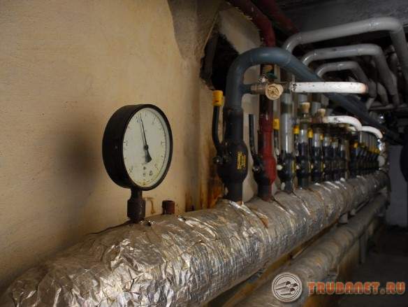
Pressure gauges used when testing pipelines must be checked and sealed. Pressure gauges must meet an accuracy class of at least 1.5 according to GOST 2405-63, have a body diameter of at least 150 mm and a scale for a nominal pressure of about 4/3 of the measured pressure. Thermometers used for pneumatic testing must have a division value of no more than 0.1 deg.C.
Hydraulic testing checks pipelines simultaneously for strength and density.
Strength test pressure value installed by the project; it should be equal to:
- For steel pipes pipelines at operating pressures up to 4 kgf/cm 2 and for pipelines designed to work with wall temperatures above 400° C, 1.5 operating pressure, but not less than 2 kgf/cm 2 ;
- For steel pipelines at operating pressures from 5 kgf/cm2 and above 1.25 operating pressure, but not less than operating pressure plus 3 kgf/cm2;
- For other pipelines, 1.25 working pressure, but not less than 2 kgf/cm 2 for cast iron, vinyl plastic, polyethylene and glass;
- 1 kgf/cm 2 for pipelines made of non-ferrous metals and alloys;
- 0.5 kgf/cm 2 for faolite pipelines.
To create the required pressure in the pipeline during hydraulic testing, mobile plunger pumps (NP600, GN1200400), piston hand pumps (TN500, GN200), hydraulic presses (VMS45M), gear drive (NSh40), as well as service pumps are used.
The hydraulic test process consists of the following operations: connecting a hydraulic pump or press; installation of pressure gauges; filling the pipeline with water (in this case, the vents should be kept open until water appears in them, which indicates complete displacement of air from the pipeline); inspection of the pipeline when filling it with water in order to detect leaks through cracks and leaks in connections; creating the required test pressure with a hydraulic press or pump and holding the pipeline under this pressure; reducing the pressure to working pressure and re-inspecting the pipeline; emptying the pipeline; Removing the hydraulic pump and pressure gauges.
All pipelines withstand test pressure for 5 minutes, with the exception of glass ones, which are kept for 20 minutes.
Inspect pipelines after the pressure in the pipeline decreases to operating pressure. When inspecting steel pipelines, welds at a distance of 1520 mm on both sides of them are easily tapped with a rounded hammer weighing no more than 1.5 kg, and when inspecting pipelines made of non-ferrous metals, with a wooden hammer weighing no more than 0.8 kg. Tapping pipelines made of other materials is not permitted.
Hydraulic test results for strength and density are considered satisfactory if during the test there was no pressure drop on the pressure gauge, and in the welds, flange connections and seals, no leaks or sweating were detected. If the test results are unsatisfactory, the defects should be eliminated and the test repeated.
At negative ambient temperatures, a hydraulic test of the pipeline is carried out, ensuring the necessary measures against water freezing, especially in the drain lines (preheating or adding an aqueous solution of calcium chloride).
After a hydraulic test in autumn-winter, the pipelines are blown with compressed air to completely remove water. Blowing should be done very carefully to avoid stagnation of water at the lowest points of the pipeline.
Testing of pipelines made of polymer materials is carried out in accordance with SNiP Sh-29-76 and SN 440-83. Before testing, the pipelines are subjected to an external inspection in order to establish the compliance of the installed pipelines with the design and their readiness for testing. During inspection, check the condition of the installation joints, the correct installation of fittings, supports and hangers, the ease of opening and closing it locking devices, correct installation of compensators, the ability to remove air from the pipeline, fill it with water and empty it after testing.
Tests must be carried out at an ambient temperature not lower than minus 15 ° C for pipelines made of LDPE and HDPE and not lower than 0 ° C for pipelines made of PVC and PP, and no earlier than 24 hours after welding or gluing the last joint.
Before testing external pipelines, they must be blown out to clean the internal surface of dirt. The cavity of internal pipelines and pipelines of gas control points is cleaned before their installation.
The pipeline testing method must be specified in the design. In the absence of such instructions in the project, testing a pipeline made of polymeric materials, as a rule, should be carried out using a hydraulic method.
Tests for the strength and density of pipelines are carried out by the installation organization in the presence of representatives of the customer and the gas utility company, which is recorded in the relevant act.
The pipeline or its section to be tested is disconnected from the equipment, other pipelines or sections using plugs with shanks, the dimensions of which are given in Table. 55. Use for-
Vacuum fittings to disconnect the tested section of the pipeline are prohibited.
The pressure in the pipeline is monitored using two pressure gauges, one of which is a control one. Pressure gauges must have seals installed by State control laboratories after inspection carried out once a year.
Defects discovered during testing are eliminated after the pressure is reduced and the pipeline is freed from water. Tapping welded and adhesive seams during testing is not allowed. Defective joints made by contact welding are cut out and “coils” with a length of at least 200 mm are welded in their place. IN Lately repair of defective joints is carried out by welding on the remaining couplings. If necessary, tighten the connections, first loosening the clamps of the nearest supports. After tensioning, the pipeline is secured again. After all defects have been eliminated, the pipeline is tested again. Relevant acts are drawn up on testing and permission is obtained to connect the installed and tested section (line) of the pipeline to the existing ones.
Pipeline tests are carried out under the direct supervision of a foreman or other work manager in accordance with the requirements of SNiP II1-4-80 on safety precautions in construction and CM 440-83.
Hydraulic tests. Before carrying out hydraulic tests, it is necessary to carry out preparatory work:
— install devices for releasing air at the upper points of the pipeline being tested - “air vents”;
— install drainage (water drainage) at the lowest points; install pressure gauges at the beginning and end of the pipeline being tested;
— connect the pipeline under test to a pump or water supply system that creates the necessary pressure and ensures that the pipeline is filled with water;
— take measures against water freezing, especially at low points and drain lines (use of solutions with a low freezing point or heated water up to 40 ° C for LDPE and PVC pipes and 60 ° C for HDPE and PP pipes).
Tests are carried out in the following sequence. Fill the pipeline with water with the vents open. When water appears, the vents close and begin to gradually increase the pressure to the value required for the strength test. Upon reaching the pressure of a given value, pipelines made of thermoplastics are kept for 15...30 minutes and during this time they maintain the pressure by pumping water with a pump, since these pipelines are subject to elastic deformation. After stabilization, the pipeline is maintained under test pressure for 5 minutes, then the pressure is reduced to operating pressure and maintained for 30 minutes. At this time, an external inspection of the pipeline is carried out, paying special attention to the joints. The operating pressure test is a density test.
After the test, open the “air vents”, the outlet pipe or the drainage device and free the pipeline from water. The results of the hydraulic test are considered satisfactory if the pressure does not drop during soaking, and there are no leaks or sweating in the welds, flange connections and seals.
Simultaneous hydraulic testing of several pipelines mounted on one overpass or supporting structures is carried out if these structures are designed for the appropriate loads.
Pipelines laid in trenches or impassable channels are tested twice. Before filling the trench and installing the fittings, preliminary tests of the pipeline are carried out. The value of the preliminary test hydraulic pressure during the strength test must be equal to the calculated operating pressure for a given type of pipe, multiplied by a factor of 1.5.
The final hydraulic test of the pipeline is carried out after filling the trench and completing all work on this section of the pipeline, but before installing hydrants, safety valves, instead of which plugs are installed during testing. The value of the final test hydraulic pressure must be equal to the design pressure for a given type of pipe, multiplied by a factor of 1.3.
Preliminary hydraulic testing of pressure plastic pipelines is carried out in the following sequence. The pipeline is filled with water and kept without pressure for 2 hours. After this, a test pressure is created in it and maintained for 0.5 hours. Next, the test pressure is reduced to the design working pressure, maintained at this pressure for at least 0.5 hours and inspected pipeline. Since the pipeline shell is deformed during testing, it is necessary to pump water to maintain test or operating pressure in the pipeline.
A pressure plastic pipeline is considered to have passed the preliminary hydraulic test if, at the test pressure, no ruptures of pipes or joints and fittings are detected, and at operating pressure there are no visible water leaks or sweating of the joints.
Conducting final hydraulic tests for the density of water supply and sewerage pipelines begins no earlier than 48 hours after filling the trench and no earlier than 2 hours after filling the pipeline with water.
The final hydraulic test is carried out in the following sequence. A pressure equal to the design operating pressure for a given type of pipe is created in the pipeline and maintained for 2 hours. When the pressure drops by 0.02 MPa, water is pumped in. Then, in no less than 10 minutes, the pressure is raised to the test level and maintained for 2 hours. If the pressure drops by 0.02 MPa during this period, water is also pumped in. Water leakage is then determined by measuring the amount of water added to maintain the test pressure.
Hydraulic tests of gravity sewer networks from polymer pipes is carried out twice: without wells (preliminary) and together with wells (final). Preliminary tests of sewerage pipelines must be carried out in separate sections located between wells, selectively as directed by the customer. If the results of the random test are unsatisfactory, then all sections of the pipeline are subject to testing.
Preliminary tests of sewerage pipelines are carried out in an unfilled trench under a hydraulic pressure of 0.05 MPa and held for 15 minutes. If there are no visible water leaks in the butt joints, it is allowed to maintain the test pressure by pumping water.
The final testing of the sewerage pipeline together with the wells is also carried out selectively - two adjacent sections with an intermediate well and wells at the ends of the pipeline. The site for final testing is selected as specified by the customer.
The tested section of the pipeline is considered to have passed the density test if the leakage value is less than or equal to the leakage value through the walls and bottom of the wells at 1 m of their depth, corresponding to the permissible leakage value accepted per 1 m length of concrete or reinforced concrete pipes, the diameter of which is equal to the internal diameter of the wells -dev.
Hydraulic tests of sanitary systems made of polymer pipes are carried out at positive temperatures environment no earlier than 24 hours after the last welded joint. The value of the test pressure at the lowest point of the pressure pipeline is taken equal to: for type T pipes - 1.5 MPa; C - 0.9 MPa; SL - 0.6 MPa; L - 0.38 MPa. Hydraulic tests are carried out after filling the pipeline with water and checking the absence of air in it by holding it under test pressure for at least 30 minutes and externally inspecting the pipeline. For pipelines made of HDPE and LDPE, the pressure during testing and inspection is maintained at a given level with a deviation of no more than 0.05 MPa. The pipeline is considered to have passed the test if no leaks or other defects are found.
Hydraulic testing of internal drainage systems is carried out by filling them with water to the full height of the risers. Tests are carried out after external inspection of pipelines and elimination of external defects. Hydraulic tests begin 24 hours after completion of welding work. The drainage system is considered to have passed the test if, after 20 minutes after filling it with water, an external inspection reveals no leaks or other defects, and the water level in the risers does not decrease.
Pneumatic testing of thermoplastic pipelines during ground and underground installation produce:
— at ambient temperatures below 0 °C;
- If support structures not designed to fill the pipeline with water;
- if the use of water is unacceptable for technical reasons;
- in the absence of water for testing in the required quantities.
Pneumatic density tests can only be carried out after strength testing by any method. It is not permitted to carry out pneumatic strength tests of pipelines in operating workshops of industrial enterprises, on overpasses and channels where operating pipelines are located. For pneumatic tests, air or inert gas is used.
The length of the section of the intra-shop pipeline subjected to pneumatic testing should not exceed for a pipeline with a diameter of up to 200 mm no more than 100 m, for Z)„ more than 200 mm - no more than 75 m. The length of the section of the inter-shop pipeline, respectively, at 0„ to 200 mm - no more 250 m and for DH more than 200 mm - no more than 200 m.
The strength test pressure is maintained for 5 minutes, after which it is reduced to the working pressure at which the pipeline is inspected. The pressure during pneumatic testing is raised gradually with inspection of the pipeline when it reaches 0.6 test pressure for a pipeline with a working pressure of up to 0.2 MPa and with inspection when it reaches 0.3 and 0.6 test pressure for pipelines with a working pressure over 0.2 MPa . During pipeline inspection, the pressure rise stops.
During pneumatic testing of plastic process pipelines defects are detected in the following ways: by sound, by coating welded, adhesive and flange joints with a soap solution (emulsion), and with halogen leak detectors.
Soap emulsion is prepared from a soap solution with the addition of glycerin (40 g of soap and up to 10 g of glycerin per 1 liter of water). When pneumatic testing of plastic pipelines in winter (up to minus 15 ° C), a soap emulsion of the following composition is prepared: technical glycerin - 450 g, water - 515 g and soap powder - 35 g. If halogen-containing gases are used when testing thermoplastic pipelines, Halogen leak detectors of various designs are used.
It is necessary to measure the gas pressure in the pipeline during testing only after the temperature in the pipeline has equalized. For pneumatic tests with pressures up to 0.01 MPa, liquid U-shaped pressure gauges filled with water are used to control pressure; at pressures above 0.01 MPa, U-shaped mercury pressure gauges or spring ones are used; at pressures of 0.1 MPa, spring pressure gauges of a class not lower than 1.5. Pressure gauges are installed at the beginning and at the end of the tested section of the pipeline.
The need to test plastic pipelines for density with determination of pressure drop and its permissible values are established by the project for pipelines located outside buildings and workshops. In the absence of special instructions in the design, the test duration should be at least 12 hours.
The permissible pressure drop in technological plastic pipelines DH up to 250 mm, transporting toxic substances and located outside buildings, must not exceed 0.1% h of test pressure; 0.2% h - for pipelines transporting hot and other active gases. For pipelines DH more than 250 mm, the pressure drop standards during testing are determined by multiplying these values by the coefficient /C = 250/DBH, where DB„ is the internal diameter, mm, of the pipeline being tested.
Conducting preliminary and final testing of gravity sewer networks from polyethylene pipes large diameters can be carried out pneumatically. A preliminary test is carried out before the final filling of the trench. A test pressure of compressed air equal to 0.05 MPa is maintained in the pipeline for 15 minutes. At the same time, the welded joints are inspected and leaks are detected by the sound of leaking air, by bubbles formed in places of air leakage when washing the welded joints with soap emulsion.
The final pneumatic test is carried out at a level groundwater in the middle of the tested pipeline is less than 245 kPa. Final pneumatic tests are carried out on sections ranging from 20 to 100 m in length, and the pressure difference between the highest and lowest points of the pipeline should not exceed 245 kPa. Pneumatic tests are carried out 48 hours after filling the pipeline.
Pneumatic tests are carried out in the following sequence. The compressor creates pressure P in the pipeline, checks the tightness of the plugs and maintains this pressure for 10 minutes. Next, close the air supply valve and after 2 minutes measure the time for the air pressure in the pipeline to drop to level Pi. The pipeline is considered to have passed the pneumatic test if the time during which the test pressure drops from level P to level Pi is at least 11 minutes for HDPE pipes with a diameter of up to 700 mm, 12 minutes for pipes made of HDPE up to 700 mm, 12 minutes for pipes up to 800 mm, 14 minutes for pipes made of HDPE up to 900 mm. up to 1000 mm - 16 min, up to 1200 mm - 18 min.
After testing, the pipeline must be washed or purged in order to remove dirt and foreign particles that entered the pipeline during installation and welding of field joints. Washing is done with water, and purging with compressed air or inert gas. Flushing should be carried out with drinking quality water or technical water at a temperature of 5...30°C at a water speed in the pipeline of 1...1.5 m/s until a stable appearance of clean water from the outlet pipe or drainage device, the diameter of which must be at least half the diameter of the pipeline being flushed. During flushing, the shut-off valves on the pipeline must be open and the valves removed.
The duration of flushing with chlorinated water of drinking water supply pipelines installed from polyvinyl chloride pipes must be at least 12 hours.
After flushing, the pipeline is freed from water and, if necessary, blown with compressed air to remove its residues.
Purge of process pipelines with compressed air is carried out at operating pressure, preventing the pressure at the end of the pipeline from decreasing by more than 0.01 MPa. The duration of purging is at least 10 minutes at a temperature not exceeding 30 °C. Blowing through plastic pipelines with steam is strictly prohibited.
After flushing and purge, it is necessary to restore the entire section of the pipeline, remove or plug all fixtures and devices for testing, flushing or purge. Relevant reports are drawn up on testing, washing and purging.
Only proper and reliable functioning of the heating system can ensure calm and normal life of the population during the winter season. Sometimes various kinds of extreme situations occur, in which the performance of the system may differ significantly from civilian conditions. Hydraulic testing of pipelines and pressure testing are necessary to prevent situations that may arise during the heating season.
Purpose of hydraulic tests
As a rule, any heating system operates in standard mode. The working pressure of the coolant in low-rise buildings is generally 2 atm, in nine-story buildings - 5-7 atm, in multi-storey buildings - 7-10 atm. In a heating system laid underground, the pressure can reach 12 atm.
Sometimes unexpected pressure surges occur, which leads to an increase in pressure in the network. As a result, testing of heating pipelines is necessary to check the system not only for its ability to function under standard normal conditions, but also for its ability to overcome water hammer. 
If for some reason the heating system has not been checked, then serious accidents may occur subsequently due to water hammer, which will lead to the flooding of premises, equipment, furniture, etc. with boiling water.
Sequence of work
Conducting hydraulic tests of pipelines should be carried out in the following sequence.
- Pipeline cleaning.
- Installation of taps, plugs and pressure gauges.
- Water and
- The pipelines are filled with water to the required value.
- The pipelines are inspected and places where defects were found are marked.
- Elimination of defects.
- Carrying out the second test.
- Disconnection from the water supply and draining water from pipelines.
- Removing the plug and pressure gauges.
Preparatory work
Before performing hydraulic tests of heating system pipelines, it is necessary to inspect all valves and fill the valves with seals. The insulation on pipelines is repaired and checked. The heating system itself must be separated from the main pipeline using plugs. 
After completing all the necessary manipulations, the heating system is filled with water. With help pumping equipment its indicator is approximately 1.3-1.5 times higher than the working one. The resulting pressure in the heating system should be maintained for another 30 minutes. If it has not decreased, then the heating system is ready for operation. Acceptance of work on hydraulic testing is carried out by the inspectorate
and tightness
Preliminary and acceptance hydraulic tests of pipelines (SNiP 3.05.04-85) must be carried out in a certain sequence.
Strength

Tightness
- The pressure in the pipeline increases to the leak test value (Pg).
- The start time of the test (T n) is recorded, and the initial water level (h n) is measured in the measuring tank.
- After that, the decrease in pressure in the pipeline is monitored.
There are three possible options for a drop in pressure, let’s consider them.
First
If within 10 minutes the pressure indicator decreases by less than 2 marks on the pressure gauge scale, but does not become lower than the calculated internal one (P p), then the observation can be completed.
Second
If after 10 minutes the pressure drops by less than 2 marks on the pressure gauge scale, then monitoring the decrease in pressure to the internal (P p) calculated value must be continued until it drops by at least 2 marks on the pressure gauge scale.
The duration of observation should not exceed 3 hours, for cast iron, steel and asbestos-cement pipes - 1 hour. After the specified time, the pressure must decrease to the design value (P p), otherwise water is discharged from the pipelines into the measuring tank.
Third
If within 10 minutes the pressure becomes less than the internal design pressure (P p), then further hydraulic tests of heating system pipelines must be suspended and measures must be taken to eliminate hidden defects by maintaining the pipes under the internal design pressure (P p) until a thorough inspection defects that will cause an unacceptable pressure drop in the pipeline will not be detected. 
Determination of additional water volume
After completing monitoring of the drop in pressure according to the first option and stopping the coolant discharge according to the second option, you need to do the following.

Drawing up an act
Evidence that all work has been carried out is a hydraulic test report of the pipelines. This document drawn up by the inspector and confirms that the work was carried out in compliance with all norms and regulations, and that the heating system withstood them successfully.
Hydraulic testing of pipelines can be carried out in two main ways:
- Manometric method - tests are carried out using pressure gauges, devices that record pressure indicators. During operation, these devices show the current pressure in the heating system. Hydraulic testing of pipelines using a pressure gauge allows the inspector to check what the pressure was during testing. Thus, the operating engineer and inspector check how reliable the tests performed are.
- The hydrostatic method is considered the most effective; it allows you to test the heating system for performance at a pressure that exceeds the average operating rate by 50%.
Various elements of the system are tested for different times, and hydraulic tests of pipelines cannot last less than 10 minutes. In heating systems, the permissible pressure drop is considered to be 0.02 MPa.
The main condition for the start of the heating season is competently conducted and properly documented hydraulic tests of pipelines (SNiP 3.05.04-85), in accordance with the requirements of current regulatory documentation.
Hydraulic testing of water supply pipelines usually becomes the next step after completion of installation work. This stage cannot be avoided when working with networks that operate under pressure. When performing this procedure, a pump is used to build up pressure.
This contributes to the timely detection of defects. After conducting a hydraulic test of the pipeline, they proceed to drawing up a report. Only after its signing the operation of the pipeline becomes available.
When conducting hydraulic tests of water supply pipelines, specialists check several indicators at once:
- Detection of defective areas.
- Tightness.
- Reliability.
Heating testing is carried out before a newly built facility is put into operation. This applies not only to the introduction of new communications, but also to its overhaul.
If defects are found, they are eliminated as soon as possible. The tests are repeated until the results are found positive.
The pipeline tests themselves are carried out in two passes.
- First come the preliminary ones.
- These are followed by the final ones.
The first stage involves injecting water into the pipeline, under high pressure. The main thing is that the pressure is one and a half times greater than normal operating indicators.
IMPORTANT! Hydraulic testing of water supply pipelines is also prescribed before finishing the interior. Specially trained people are responsible for hydraulic testing of water supply systems.
The underground sections of the pipeline are completely closed before final testing begins. On at this stage All installation work must be completed.
But the installation of plumbing fixtures has not yet begun. During these activities, the pressure is increased by 1.3 times compared to normal.
The technique allows for additional rules.
- Hydraulic checks of water supply systems should be carried out only 24 hours after installation is completed. The ambient temperature must be above zero.
- During this event, the pipes are completely filled with water. Until it reaches the top of the risers. Before this, the condition of the pipes undergoes a visual inspection to control. If noticeable deficiencies are identified, they are corrected immediately. The system is considered to have successfully passed the test if no leaks occur within 20 minutes of operating condition. And if the water maintains the previously noted level.
Watch the video
Under what conditions is it necessary to carry out hydraulic testing of pipelines?
It is necessary to realize how complex the hydraulic testing of plumbing systems is. The reliability of the structure itself and its quality largely depend on the competence of this procedure. Therefore, the work is trusted only to specialists with the appropriate classification.

The requirements for the test work itself include several items. This is required by any technique.
- All points of use in the riser are switched on simultaneously to check efficiency. But the need at this stage is determined individually, at each enterprise separately.
- The condition of heated towel rails is tested when the hot water supply is checked.
- Temperature measurements take place only at the extreme sections of the system. Water is poured with predetermined characteristics.
- The liquid must be completely drained after completion of all stages of the activity.
- Filling of pipelines begins from the lower floors, gradually moving to the upper ones. Then the air will be properly forced out of the pipes. And there is no danger of appearing air jams in the pipeline.
- The first stage in filling the water pipeline affects only the main section. Only at the next stages do they move to small local networks, separate risers.
- Outdoors or indoors during work the temperature should not fall below +5 degrees.
Carrying out the procedure at the preliminary stage
Video: hydraulic testing of water supply and heating
Building codes govern the order in which inspections are carried out.
- First, the water supply is filled with liquid. And leave it in this state for two hours.
- Moving on to creation high blood pressure for two hours. It happens very slowly. At this stage, it is already possible to identify a number of leaks.
- The pressure is reduced until they reach the calculated values. Then they move on to examining the general condition of the route.
- This pressure is maintained for thirty minutes or more. Without such a step, the deformed shape of the pipes simply cannot be stabilized.
- The next stage is turning off the taps at the entrances. The water is slowly drained using a pressure test pump.
- The route is checked for serious problems.
IMPORTANT! It is better to find out in advance what pressure is standard for a particular line, according to SNiP. This will allow you to compare the readings with the limits shown on the devices themselves. And follow the method exactly.
What is the final hydraulic test of water supply lines?
Such hydraulic checks of water supply pipelines are carried out after completion installation of plumbing fixtures for hot water .
- They start by pumping up the working pressure in the water supply. It must be raised to the initial level if the indicator has dropped by 0.02 MPa.
- The pressure rises ten minutes before the test readings. The system remains in this state for two hours.
 It is organized before installation water fittings. And here it is assumed that the pipeline is completely filled with water. Next, follow the following sequence of actions.
- Shut off the valve that connects the hot water supply system to external networks.
- Hoses for discharging contaminated water into the sewer system are connected to drain valves responsible for emptying the risers.
But even after such washing there is no guarantee that all debris will be removed. Therefore, specialists are developing equipment that increases the effectiveness of this process.
Video: What is pressure testing of a heating system
Any similar device creates a mixture of air and hot water, which is impulsively supplied into the pipeline, which requires cleaning. When the mixture passes through the equipment, it is discharged into the sewer system. The pulsation or feed force can be easily adjusted by lengthening or shortening the time intervals.
About special equipment for crimping
The design of the injection mechanism is the main difference between pump models, without which hydraulic testing of water supply lines in accordance with SNiP becomes impossible.
 This feature allows us to divide into the following groups:
- Membrane.
- Vane-rotor.
- Piston.
A manual pressure tester is the cheapest option, suitable for heating and water supply circuits in private homes. Operator using this device, can pump up to three liters of liquid per minute into the system.
Two-stage pumps allow you to solve more serious problems. The method of their work remains approximately the same.
About regulation and other features of the process
SNiPs contain all the information related to inspections for both internal and external networks. Industry standards describe the methodology for conducting events at enterprises in a specific field of activity.
This indicator depends on several factors:
- The height difference between elements located above and below.
- The thickness of the walls.
- The material from which the pipeline is made.
Video: hydraulic test of heating pipelines
The pressure value according to SNiP usually does not exceed 10 MPa. A specific indicator is individually calculated for each type of pipeline, for certain types of hydraulic tests of water supply systems.
How is the work results report filled out?
The document must display information related to:
- Signs of a violation of tightness, reliability in threaded and welded connections, if present. Have drops appeared on the surfaces of pipes and fittings?
- The results of direct verification.
- Methods for eliminating identified faults.
- Address and date of inspection. And the names of the citizens who signed the act. Typically, signatures are provided by the owners of houses or apartments. Or this function is assigned to representatives of the repair and maintenance organization.
- The project in accordance with which the circuit was installed.
- The crimping method used in practice.
About pressure standards for crimping
When testing water supply, the pressure indicator according to SNiP depends on what indicator is considered working for a particular system. In turn, the base materials in the pipes determine the value of the operating pressure itself.

No less attention is paid to radiators used during installation work. When pressure testing is carried out in new systems, the pressure indicator according to GOST is two times higher working standard. For existing systems, an excess of 20-50 percent is acceptable.
Each type of pipe and radiator can withstand a certain maximum pressure. This factor must be taken into account when choosing the optimal performance indicator for a particular system. And when choosing the parameters on which crimping is carried out.
At the input unit, crimping deserves special attention. The minimum required level for such work is 10 atm.
Without special electric pumps, creating a parameter of this type is impossible. The result is considered positive if the parameter drops by no more than 0.1 atm in half an hour.
Private houses: we carry out pressure testing
Private houses require the use of closed water supply systems. According to GOST, the maximum operating pressure for them is 2 atmospheres.
When carrying out hydraulic tests, one cannot do without pumps with manual and electric drives, which help to build up pressure to 4 atmospheres. Connection to the heating main is acceptable.
Video: hydraulic test of cold water supply systems
Water begins to fill the structure from below, using a drain tap. Next comes the air, it easily pushes out the water. Excess is removed through valves air type, mounted at the very top. The same thing happens on every radiator. Or in places where air traffic jams appear.
To test water supply communications, use water whose temperature does not exceed 45 degrees according to GOST.
Carrying out pressure testing yourself is mandatory if the owner installs the entire pipeline system himself. The procedure is the same as in houses with many apartments.
The level of water hardness for hydraulic testing of water supply pipelines must remain low if it is then planned to be used as a coolant.
It is permissible to use melt or rain water. It is completely drained if no further use is planned.
Additional information about documents
In the report on the results of the hydraulic test, it is necessary to write about what brand of pressure gauge was used. They also indicate measurements of pressure readings in the system at the time of inspection. They write about the height at which the measuring device was located in relation to the pipe axis.
Video
The pipeline must be disinfected before it is put into operation. To do this, use ordinary water, to which active chlorine is added in an amount of 20-30 grams, according to GOST.
At the next stage, they proceed to flushing the pipeline. You can use the liquid from the pipes only if the bacteriological analysis is positive. Flushing is carried out for as long as necessary to change the liquid inside ten times.
(2
ratings, average: 5,00
out of 5)
Discussion is closed.
After installation of pipeline communications, pneumatic and/or hydraulic testing of pipelines is mandatory. Such a check is required in accordance with the SNiP regulations (NiTUHP-62 and III-G.9-62). Read about the details of the tests, their technology and nuances in this article.
Timely inspection and elimination of defects will prevent accidents
Hydraulic testing of pipelines
Preparatory work
Before carrying out hydraulic tests of heating system pipelines, it is necessary to carry out a set of preparatory work.
- The structure is divided into conventional divisions.
- An external visual inspection is carried out.
- Technical documentation is checked.
- Drain valves, plugs, and air valves are attached to the divisions.
- Install a temporary pipeline line from the filling and pressing devices.
- The section being tested is disconnected from the remaining pipe divisions using plugs with shanks, and is disconnected from the apparatus and equipment.
Important: use the complete kit for these purposes. shut-off valves the wire itself is prohibited. - To test pipelines for strength and density, they are connected to hydraulics (compressors, pumping stations, presses or air networks), creating the pressure required for testing, at a distance of 2 valves.
Hydraulic tests are carried out only under the supervision of the manufacturer or under the guidance of a foreman, in strict accordance with the requirements of technical documentation, instructions and design papers. Gosgortekhnadzor regulations and safety regulations must be observed.
Please note: equipment and test devices (pressure gauges, etc.) undergo mandatory preliminary testing and sealing. The minimum accuracy class of pressure gauges is 1.5 (according to GOST 2405-63), the minimum body diameter is 1.5 cm, the nominal pressure scale is from 4/3 of the measured value. Requirements for the division price of the thermometers used are up to 0.1° C.
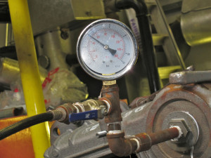
Precisely tuned measuring equipment will help identify the slightest deviation from the norm
Hydraulic tests of water supply and heating pipelines are carried out to study their strength and density. The pressure value during test experiments is established by the design documentation in kgf/cm2:
- steel structures with an operating threshold of up to 4 kgf/cm2 and systems with an operating temperature of more than 400° - 1.5-2;
- steel structures with a working threshold of more than 5 kgf/cm2 - 1.25 (in special cases, the value is calculated using the formula: working load plus 3 kgf/cm2);
- glass, vinyl plastic, cast iron and polyethylene - from 2;
- faolitic – 0.5;
- from non-ferrous metal alloys – 1.
The section being tested is isolated from other sections with plugs, and after testing the water is drained
To pump the required loads into the system, mobile plunger, operational and manual (piston) pumps, hydraulic and driven gear presses are used.
Testing
The pipeline is tested for strength and tightness using hydraulics in several stages:
- Connect a hydraulic pump or press.
- Install pressure gauges and fill the structure with water.
Important: to control the displacement of air from the pipes, the vents are left open. The water that appears in them indicates that there is no air left inside. - When filling with water, the surfaces are inspected for leaks, cracks and the slightest flaws in the connecting elements and around the perimeter.
- The required pressure is injected, and the pipeline is tested under prolonged exposure.
- The load is then gradually reduced to standard operating values to re-examine the system state.
- The water is drained from the pipeline, the equipment is removed and disconnected.
Note: glass connections are checked under test loads for 20 minutes; for wires made of other materials, 5 minutes is enough.
During the secondary inspection of steel pipes, special attention is paid to welds and joints. They are carefully tapped with a rounded hammer up to 1.5 kg, retreating 15-20 mm. To test parts made of non-ferrous alloys, a wooden hammer up to 0.8 kg is used; pipelines made of other materials are not tapped to avoid mechanical damage.
Hydrotesting of pipelines is considered successful if the pressure gauge did not show a drop in pressure during the tests, and no fogging or leaks were detected in the flange connections, seals and welds.
If the results are unsatisfactory, the test is repeated after eliminating them.
Note: sometimes for hydraulic tests at sub-zero temperatures, compounds that reduce the freezing point are added to the liquid, pipes are insulated, or the liquid is heated.
Pneumatic testing
When it is necessary

Pneumatic testing is carried out if hydrotesting is not possible
Pneumatic testing of pipelines is also used to test their density and strength or only density (in this case, a hydraulic strength test is carried out first; ammonia and freon products are not hydraulically tested).
It is used in cases where hydraulic studies are impossible for objective reasons:
- there is a requirement to use inert gases or air during testing;
- air temperature is negative;
- there is no water in the working area;
- There is too much stress in the pipeline and supporting structures due to the weight of the water.
In the cold season, for hydrotests, the liquid is heated or anti-freezing compounds are added to it.
To carry out pneumatic testing of pipelines according to SNiP, air or inert gas is used. Mobile compressors or a compressed air network are used.
Requirements for the length of divisions and pressure in kgf/cm2 during testing:
- with a diameter of less than 2 cm - 20 (length of the internal segment - 100 m, external - up to 250 m);
- with a diameter of 2-5 cm - 12 (length of the internal segment - 75 m, external - 200 m);
- if the diameter exceeds 5 cm - 6, with the length of the internal segment - 50 m, external - 150 m.
In special cases, if the project requires it, the use of other values is allowed. Tests are also carried out in strict accordance with design documentation and safety instructions, developed individually.
Important: above-ground structures made of cast iron, glass and faolite pipelines do not pass pneumatic tests. If cast iron fittings are installed on steel systems (with the exception of parts made of ductile cast iron), testing with air and inert gas is allowed if the pressure is below 4 kgf/cm2. Pre-cast iron parts undergo mandatory strength tests using water (requirement GOST 356-59).
Work order
Test stages:
- Filling the pipeline with gas or air.
- Increasing pressure, inspecting the area being tested when it reaches 0.6 of the maximum test value - for structures with a working indicator up to 2 kgf/cm2, 0.3 and 0.6 - if the working indicator exceeds 2 kgf/cm2.
Important: during inspection, it is prohibited to increase the load or hit surfaces under load with a hammer. - The final inspection occurs under operating loads.
The tightness of joints, welds, seals and flanges is measured by applying a soap solution.
To test systems that transport poisonous, flammable and toxic substances at temperatures above their boiling point, a pipeline leak test requires an additional tightness test. To do this, in parallel with the main indicators, the pressure drop is examined. All equipment connected to the system for transporting the listed types of substances is also checked.
If the pressure on the pressure gauge did not decrease during testing, and no leaks or sweating were detected in the connecting seams and seals, the result is considered satisfactory.
Testing work is entrusted to qualified employees and carried out under the guidance of the manufacturer
Only qualified employees who have undergone instructions and have the appropriate skills are allowed to test pipelines and evaluate its results. A timely and thorough check of communications will protect you from accidents, breakdowns and losses.