WATER SUPPLY AND SANITATION
(lecture course)
WATER SUPPLY AND SANITATION
(Network engineering and equipment of buildings and structures)
1. PURPOSE AND OBJECTIVES OF DISCIPLINE
The purpose of this discipline is to study the design of water supply and sewerage systems as part of engineering equipment and networks of buildings and structures in the field of civil and industrial construction.
The objectives of this discipline are:
a) study the arrangement of internal water supply and sewerage systems of buildings and structures;
b) study the design of external networks and water supply and sewerage structures.
2. BASIC COMPONENTS OF DISCIPLINE
A) Federal component: Water supply and sanitation: systems and schemes for water supply to populated areas; internal water supply of buildings and structures; internal sewerage of residential and public buildings; external sewer networks and structures.
b) Regional component: studying the design of part of the sewer systems - drainage to protect against flooding in the cities of Siberia.
V) Institute component: study of water supply and sewerage systems large city using the example of Omsk.
T ema I. Internal water supply of buildings
Internal cold (B1, B2, B3) and hot (T3) water supply.
Domestic drinking water supply B1. Water quality requirements. Elements of internal water supply: inlet, water meter unit, booster pumping unit, distribution pipeline network, water risers, floor supply pipelines, water fittings. Calculation of internal water supply: water consumption, economical speeds when selecting pipeline diameters, pressure losses in the water supply network, selection of water meters and pumps.
Fire water supply B2. B2 systems with fire hydrants. Automatic fire extinguishing systems: deluge and sprinkler systems.
Industrial water supply B3. Areas of water use in production. Water supply for construction sites. Water consumers at a construction site.
Water pipes hot water T3. Water quality requirements. Classification of hot water supply according to the location of the heat source. Elements of a centralized hot water supply system. Hot water circulation. Open (from the heating network) and closed (from water heaters) hot water supply systems.
Design, installation, testing and operation of internal water supply systems.
Topic II. Internal sewerage of buildings
Systems internal sewerage: separate (K1, K2, K3) and combined K1+K3.
Domestic sewerage K1. Elements of internal sewerage: sanitary fixtures and wastewater receivers, siphons and hydraulic valves, floor drainage pipelines, sewer risers, underground collectors, sewer outlets. Sewer pipes and shaped parts. Network cleaning devices. Ventilation of sewer networks. Construction of internal sewerage networks. Calculation of the sewer network, restrictions on flow speed, filling and slope of pipes. Diameters of internal sewerage pipelines.
Rainwater drainage of K2 buildings: internal drains. Elements of internal drains. Design and calculation of internal drains.
Industrial sewerage K3. Local installations for wastewater treatment and pumping.
Solid waste disposal: garbage chutes.
Design, installation, testing and operation of internal sewerage systems.
Topic III. Water supply: external networks and structures
Water supply systems. Water consumers. Water supply schemes for populated areas and industrial zones (using the example of Omsk). Norms and regimes of water consumption. Estimated flow rates and free water pressures. Water supply sources. Water intake structures. Pumping stations. Water pipelines. Water treatment stations: processes (cleaning and disinfection) and structures (settlers, filters, reagent and chlorine facilities). Water towers and reservoirs. External water supply networks and structures on them. Water supply to industrial enterprises: direct-flow, water reuse and recycling water supply.
Topic IV. Sewerage: external networks and structures
Purpose of sewerage. Classification of sewerage systems according to the composition of wastewater. Sewage schemes (using the example of Omsk). City sewer networks and structures on them: yard networks, street and district sewers, pumping stations, the main city sewer.
Sewage treatment plants: types of wastewater treatment and applied technological schemes. Facilities for mechanical and biological treatment, wastewater disinfection and sludge treatment. The operating principle of sedimentation tanks, aeration tanks, and digesters.
Rain (storm) drainage of cities. Drainage in industrial and civil construction to lower the groundwater level: protection against flooding in Siberian cities. Connection drainage systems to the rain drain.
4. Work plan of studies for the 5th or 6th semester
5. Practical classes (5th or 6th semester)
Get full text|
Lesson topic |
Quantity |
|
|
Selecting a system and developing an internal water supply scheme | ||
|
Construction of an axonometric diagram of a water pipeline | ||
|
Hydraulic calculation of water supply | ||
|
Selection of water meters and pumps | ||
|
Selecting a system and developing a building sewerage scheme | ||
|
Construction of an axonometric sewerage diagram | ||
|
Hydraulic calculation of the sewer network | ||
|
Construction of a longitudinal profile of a yard sewerage system | ||
|
TOTAL hours |
6. LITERATURE
BASIC:
2. Guidelines to implementation course work on water supply and sewerage of a residential building / Compiled. – Omsk: SibADI, 19с. -(1st edition).
3. Guidelines for completing coursework on water supply and sewerage in a residential building / Compiled by. – Omsk: SibADI, 20с. -(2nd edition).
4. Hydraulics, water supply and sewerage: textbook for universities / etc. – M.: Stroyizdat, 1980. – 359 p.
5. Internal sanitary installations. Part 2. Water supply and sewerage. - M.: Stroyizdat, 19с. -(Designer's Handbook).
6. SNiP 2.04.01-85. Internal water supply and sewerage of buildings. –M.: CITP Gosstroy USSR, 1986. –56 p.
7. SNiP 2.04.02-84. Water supply. External networks and structures. –M.: Stroyizdat, 1985. –136 p.
8. SNiP 2.04.03-85. Sewerage. External networks and structures. –M.: CITP Gosstroy USSR, 1986. –72 p.
9. SNiP 3.05.01-85. Internal sanitary systems. –M.: CITP Gosstroy USSR, 1986. –40 p.
10. GOST 21.601-79. Water supply and sewerage. - M.: Standards Publishing House, 19 p.
11. GOST 21.604-82. Water supply and sewerage. External networks. - M.: Standards Publishing House, 19 p.
ADDITIONAL:
1. SNiP 2.06.15-85. Engineering protection of the territory from flooding and flooding. –M.: CITP Gosstroy USSR, 1986. –20 p.
2. Forecasts of flooding and calculation of drainage systems in built-up areas / VNII VODGEO: etc. – M.: Stroyizdat, 1991. – 272 p. (Reference manual for SNiP).
3. Degtyarev in industrial and civil construction. –M.: Stroyizdat, 1990. –238 p.
4. Sologaev from flooding in urban construction. Device and operation. Omsk: Publishing house SibADI, 19s.
Course work on water supply and sewerage of a residential building consists of calculations and a graphic part in the volume of 1 sheet in A1 format (594x841 mm). On a sheet of Whatman paper (or graph paper) the following are drawn and displayed:
1) plan of the technical underground with drawing and designation of all pipelines and risers of the water supply and sewerage systems of the building, including water supply input and sewerage outlets - scale 1:100 or 1:200;
2) axonometric diagram of the internal water supply cold water with the application of shut-off and water fittings and designation of the water supply input, risers, pipe diameters and characteristic elevations - scale 1:100 or 1:200;
3) axonometric diagram of a sewer riser with an outlet to the first inspection well with the application of sanitary equipment and the designation of the riser, outlet, pipe diameters, their slopes and marks of pipe trays - scale 1:100 or 1:200;
4) longitudinal profile of the yard sewerage system to the inspection well of the external network - horizontal scale 1:500, vertical scale 1:100;
Literature ( minimum set from the library):
1. Program for water supply and sanitation / Compiler. – Omsk: SibADI, 1991. – 4 p.
2. Guidelines for completing coursework on water supply and sewerage in a residential building / Compiled by. – Omsk: SibADI, 19с.
3. Hydraulics, water supply and sewerage: a textbook for universities / etc. – M.: Stroyizdat, 1980. – 359 p.
4. SNiP 2.04.01-85. Internal water supply and sewerage of buildings. –M.: CITP Gosstroy USSR, 1986. –56 p.
NOTE:
A complete set of literature is listed in the WORK PROGRAM. Full set literature is in in electronic format in Lotus Notes (WATER SUPPLY) in computer class auditorium on the 3rd floor of the 4th building of SibADI (near the Drama Theater).
ACCEPTED ABBREVIATIONS
B1 – domestic and drinking water supply.
B2 – fire water supply system.
B3 – industrial water supply.
K1 – domestic sewerage.
K2 – rainwater drainage.
K3 – industrial sewerage.
St V1-1 – water supply riser B1 in numbering order 1st.
St K1-1 – sewer riser K1 in numbering order 1st.
KV1-1 – water supply well B1 in numbering order 1st.
KK1-1 – sewer well K1 in numbering order 1st.
l– pipeline length at the design section, m.
N– the number of devices served by the design area.
U– number of water consumers (residents).
P- probability joint action devices.
q C is the estimated flow of cold water on the site, l/s.
q 0C – standard consumption of cold water by the device, l/s.
d– internal diameter of the pipeline, mm.
V – speed of water movement in the pipeline, m/s.
i– hydraulic slope.
kL– coefficient for taking into account local pressure losses.
D H– pressure loss on the design section of the pipeline, m.
Legend
– visible section of pipeline B1 (open installation).
– invisible section of pipeline K1 (hidden gasket).
– intersection of pipes.
– water tap.
– watering tap.
– float valve of the toilet cistern.
– faucet for sink or washbasin.
– mixer with shower net.
– common mixer for bath and washbasin.
– shut-off valve (diameter 15, 20, 25, 32, 40 mm).
– valve (diameter 50 mm or more).
- Check Valve.
– water meter (water flow meter).
– pressure gauge.
– centrifugal pump.
– vibration insert (reinforced rubber hose).
- kitchen sink.
- wash basin.
- bath.
- toilet with oblique outlet.
– floor drain with siphon (hydraulic seal).
– bell-type drainage funnel (for unused roofs).
– flat drain funnel (for roofs in use).
– bell-shaped sewer pipe.
– transition pipe (usually for transition from Æ 50 mm to Æ 100 mm).
– elbow (for turning sewerage pipelines by 90°).
– bend (for turning sewerage pipelines by 135°).
– straight tee (for risers).
– oblique tee (mainly for horizontal sections).
– straight cross (for risers).
– oblique cross (mainly for horizontal sections).
– crank type siphon (under washbasins and sinks).
– bottle-type siphon (under washbasins and sinks).
– bath siphon.
– revision.
Section 1
Internal water supply of buildings
The internal water supply of buildings is a system of pipelines and devices that supply water inside buildings, including the water supply input that is located outside.
The internal water supply includes:
1) pipelines and connecting fittings (fittings);
2) fittings (taps, mixers, valves, gate valves, etc.);
3) instruments (pressure gauges, water meters);
4) equipment (pumps).
Symbols for internal water supply see above.
Classification of internal water supply systems
Classification internal water pipes shown in Fig. 1.

Thus, the internal water supply is divided primarily into cold (C) and hot (T) water supply. On diagrams and drawings in domestic documentation, cold water pipes are designated by the letter of the Russian alphabet B, and hot water pipes by the letter of the Russian alphabet T.
Cold water pipes have the following varieties:
B1 - domestic drinking water supply;
B2 - fire water supply;
B3 - industrial water supply (general designation).
A modern hot water supply must have two pipes in the building: T3 - supply, T4 - circulation. In passing, we note that T1-T2 designate heating systems (heating networks), which do not relate directly to the water supply system, but are connected to it, which we will consider later.
b) not lower than +50°C ¾ for centralized hot water supply systems connected to closed heat supply systems;
c) not higher than +75°С ¾ for all systems specified in subparagraphs “a” and “b”.
3) In the premises of preschool institutions, the temperature of hot water supplied for showers and washbasins should not exceed +37 °C.
Classification T3-T4 according to the location of the heat source
The classification of hot water supply T3-T4 according to the location of the heat source is shown in Fig. 7.
Rice. 7
It should be noted that external hot water supply networks are usually not laid, that is, hot water supply T3-T4 ¾ is typically an internal water supply system. The classification shown in Fig. 7 reflects the fact that the location of the heat source is decided centrally or locally. In large and medium-sized cities, heat is carried by external water heating networks T1-T2 and heat is supplied to buildings by separate inputs T1-T2. This centralized systems heat supply. In small towns and populated areas, the heat source is located in a house or apartment - this is a house boiler room or hot water column, running on gas, fuel oil, oil, coal, wood or electricity. This is a local system.
Open the hot water system (see Fig. 7) takes water from return pipeline heating network T2 directly, directly, and then water flows through pipe T3 to the mixers in the apartments. This hot water supply solution is not the best from the point of view of ensuring the potable quality of hot water, since the water actually comes from the water heating system. However, this solution is very inexpensive. In this way, for example, most buildings on the right bank of Omsk are supplied.
Closed The hot water supply system (see Fig. 7) takes water from the cold water supply B1. The water is heated using water heater-heat exchangers (boilers or high-speed) and flows through the T3 pipe to the mixers in the apartments. Some of the unused hot water circulates inside the building through the T4 pipeline, which maintains a constant required water temperature. The heat source for water heaters is the supply pipe of the heating network T1. This hot water supply solution is already better from the point of view of ensuring the drinking quality of hot water, since the water is taken from the drinking water supply system B1. In this way, for example, most buildings on the left bank of Omsk are supplied.
Elements T3-T4
Let's look at the elements of hot water supply T3-T4 using the example of Fig. 8.
1 ¾ input of the heating network into the technical underground of the building. This is not a hot water supply element.
2 ¾ thermal unit. Here the scheme is implemented ( open or closed) hot water supply.
Get full text3 ¾ water meter on the supply pipe of the hot water supply T3 at the heating unit.
4 ¾ distribution network of supply pipelines T3 hot water supply.
5 ¾ supply riser T3 hot water supply. A shut-off valve is installed at its base.
6 ¾ heated towel rails on T3 supply risers.
7 ¾ apartment hot water meters on floor-by-floor connections T3.
8 ¾ floor hot water connections T3 (usually Æ 15 mm).
9 ¾ mixing fittings (Fig. 8 shows a common mixer for a washbasin and a bathtub with a shower screen and a swivel spout).
10 ¾ circulation riser T4 hot water supply. A shut-off valve is also installed at its base.
11 ¾ outlet network of circulation pipelines T4 hot water supply.
12 ¾ water meter on the circulation pipe of the hot water supply T4 at the heating unit.
INSTALLATION, TESTING AND OPERATION OF INTERNAL WATER PIPES
INSTALLATION OF INTERNAL WATER PIPES
Work on the installation of internal water supply systems in buildings is usually carried out by specialized installation organizations, which are subcontractors in relation to purely construction organizations (general contractors), for example, some installation company in relation to a construction trust.
Installation is carried out in accordance with the provisions of SNiP 3.05.01-85 “Internal sanitary systems”. Before installation begins, before installers arrive at the construction site, builders must do:
3. Sanitary cabins. It is used in large-panel housing construction. The main pipelines and fittings are installed in the cabin at the factory, and during construction the cabin only needs to be carefully joined along the axes.
As soon as the installation of the water supply is completed, the next stage begins: testing.
TESTING INTERNAL WATER PIPES
Testing of the installed internal water supply system is carried out in the presence of a commission consisting of representatives:
a) the customer;
b) general contractor (construction organization);
c) subcontractor (installation organization).
The following system indicators are checked:
1) Expenses. For example, the normal flow rate of cold water from a tap or mixer should be at least 0.2 l/s.
2) Pressures. The minimum free pressure at the most distant and highest water tap on the top floor should not be less than 2-3 meters of water column.
3) The system must correspond to the design in terms of dimensions, elevations, pipe diameters, their material, including water quality indicators.
4) There should be no leaks or leaks on the pipelines.
The internal water supply is tested for 10 minutes at a pressure one and a half times higher than the maximum permissible excess (gauge) pressure for a given system. For example, for a domestic drinking water supply, the maximum permissible excess (gauge) pressure is 0.45 MPa or 45 meters of water column. Then the test pressure will be 0.675 MPa or 67.5 m of water. Art. If the system has successfully passed the pressure test, that is, has not leaked, then a pressure test report for tightness is finally drawn up in the form of Appendix 3 of SNiP 3.05.01-85, which is signed by representatives of the above-mentioned commission.
After testing, the internal water supply system is ready to be transferred for operation.
OPERATION OF INTERNAL WATER PIPELINE
The operation of internal water supply systems is under the authority of PZhREU (industrial housing repair and maintenance areas) or under the authority of the department of the chief power engineer or mechanic of enterprises - this depends on the ownership of the building (municipal or departmental) and on the type of system (B1, B2, B3, T3-T4 ).
The work performed is as follows:
Current repairs at the request of residents (changing valve gaskets, replacing faulty fittings, equipment, eliminating leaks in pipes, installing clamps, replacing sections of pipes with a high degree of corrosion damage, etc.);
Get full textUrban rainwater drainage
Rainwater drainage systems in K2 cities are designed in accordance with the requirements of SNiP 2.04.03-85 “Sewerage: external networks and structures.” Its old name: storm drain, shower.
The K2 rainwater drainage system collects rain and melted water throughout the city. surface water, discharges them by gravity through the K2 network and through its district collectors discharges conditionally clean wastewater into the reservoir in the city If necessary, additional treatment facilities are built, mainly for mechanical treatment, and in conditions of flat, flat terrain, pumping stations are installed.
Elements of external rainwater drainage:
1 ¾ storm inlets-grids, installed along roads at intervals of 50-80 meters;
2 ¾ underground outlet pipeline with a diameter of at least Æ 200 mm;
3 ¾ street collectors with a diameter of Æ mm;
4 ¾ district collectors with a diameter of Æ mm.
K2 wastewater from the territories of industrial enterprises is treated, mainly in mechanical structures.
Drainage to lower groundwater levels
Drainage is an engineering system of drains (pipes with holes), filter bedding, layers and other elements, designed to lower the water level to at least the drainage rate or at least 0.5 meters below the basement floor, the base of the structure with the discharge of drainage water:
To the rainwater drain K2;
A nearby body of water or watercourse;
The underlying underground layer.
Drainage is most often associated with the K2 rainwater drainage system, but unlike it, it drains underground water rather than surface water.
We list the main elements of drainage:
1) water intake device (drain, well);
2) filtering coatings and layers (protection against siltation);
3) inspection wells (for ease of maintenance and repair);
4) drainage pipe (drainage collector);
5) pumping station for pumping drainage water (not always);
6) pipe-outlet of drainage water (into K2, reservoir or formation).
Rice. 18. Drainage elements (using the example of ring drainage)
Let's look at the drainage elements using the example of a ring drainage (Fig. 17). It protects the basement of the house from flooding with groundwater. Drains 1 are laid around the building at such a depth that the GWL depression curve is at least 0.5 meters lower relative to the basement floor. The drains are covered with layers of crushed stone (in close proximity) and sand (between the crushed stone and the surrounding soil) to protect the internal space of the drains from silting with soil particles. Groundwater passes through the filter bed 2 and, quite clean, enters the drain 1 through water intake holes or slits. The underground water that gets inside the drain is called drainage runoff, which is drained by gravity through the drains and through one of the inspection wells 3 enters the drainage collector 4 into the reservoir of the pumping station 5. From there drainage water from time to time, they are pumped into the rainwater collector K2. Element 5 is not always needed.
Drainages for industrial and civil construction are discussed in another course: “Protection against flooding in urban construction” (Author: SibADI, Omsk, 2000). The regulatory document is SNiP 2.06.15-85 “Engineering protection of the territory from flooding and flooding.”
END OF LECTURE COURSE
During construction sewer wells utility workers try to leave certain information about them on the walls or using special signs.
Inscriptions can be seen on almost every house. They have become so common that no one notices them. The designation of sewer wells on the ground has several options.
An example of a designation on the facade of a building
Sewer wells are marked on walls or on special signs. The marking is done so that utility services can easily find the hatch in any weather conditions.
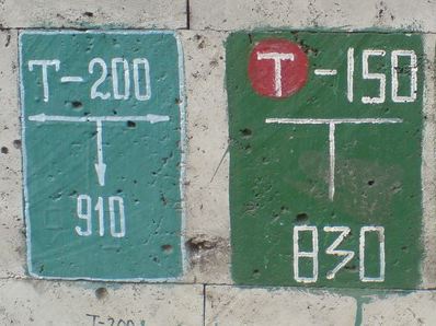
Safety markings
The designation of sewer wells on plates has its own characteristics. The color of the indicator indicates the types of hazards of the container.
Blue and white backgrounds of inscriptions are considered the safest. They show that sewerage and water supply are very close.
Red signs indicate dangerous devices. In addition, fire hydrants are also indicated on red plates. According to standards, numbers on light-colored plates must be printed in black. The shade of the letters does not matter. The upper numbers show the distance from the wall along the rear axis. The lower numbers indicate the distance the hatch is offset from the main axis.
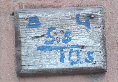
See transcript below
If you decipher the picture above, you can understand that you need to move 5.5 meters away from the wall and immediately turn right 0.5 meters. The distance to the hatch is indicated by numbers near the letter “T”.
There are green signs on the walls. They refer to gas manholes or “carpets”. The numbers on the indicators are indicated in centimeters.
Let's look at the letter designations of sewer wells
The types of sewer wells on the plates have certain abbreviations:
- linear well - “CL”;
- observation room - “C”;
- cumulative - “KN”;
- rainwater well – “D”;
- rotary well - “KP”;
- control – “K”;
- standard differential - “TPK”;
- mine – “Ш”;
- borehole – “BS”;
- cable inspection well - “KSK”.
In addition, on signs and hatches there are letter designations, which describe the type of sewerage. The letter "B" stands for water mains, "K" stands for sewer, and "D" stands for storm drain.

Examples of other markings
Marking sewer wells in the area is a very useful and necessary measure. It allows you to quickly find a sewer hatch in any case.
Unfortunately, the signs are often painted over by home owners, which prevents quality work utilities. Do not do that.
We hope that the article was useful to you. We will be grateful if you share the link to it with your friends, share it on in social networks. Let everyone who needs it learn about the nuances of marking sewer manholes from the article on our portal.
Have a nice day.
Read also:
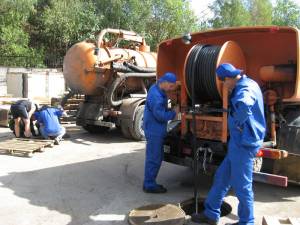 Pumping out sewer wells - do it yourself or order it from professionals?
Filtration well - types and nuances of use
Pumping out sewer wells - do it yourself or order it from professionals?
Filtration well - types and nuances of use
Symbols on water supply and sewerage drawings must be indicated not only during construction multi-storey buildings, but also in the construction of small houses. Regardless of the type of building, special symbols. They are regulated by GOST, and they are used in any programs that allow you to create drawings of sewerage and water supply systems, including AutoCAD.
For the most part, modern buildings are equipped with systems that are responsible for meeting sanitary standards. As a rule, this is a whole complex of engineering communications, which includes a hot and cold water supply system, sewerage, gas supply, garbage chute, drains, and heating. All this is necessary for people to live comfortably in a residential building. But in order for all systems to work correctly, the risks of problems must be minimized. And so that in case of any breakdowns the problem can be immediately eliminated, everything is carefully planned. The most important systems, including sewerage and water supply, must be thought out with the highest possible quality, drawn up, and then executed in accordance with a pre-drawn plan. Only if the drawing is drawn up correctly and all its requirements are met, it is possible to build a building that will meet all standards of livability and comfort.
Sewerage and water supply design
These systems play a very important role in people's lives. The comfort of the residents of the house, as well as the amenities of the premises, depend on how correctly the drawing of the sewerage and water supply is drawn up. Drainage systems play a special role. Some people believe that there is nothing complicated about installing a sewer system, but, in fact, drawing up its design is a very large, labor-intensive and responsible job. If you make even the slightest mistake, it will definitely show itself. Sometimes it comes to the point that design inaccuracies lead to the fact that the house turns out to be uninhabitable.
A sewer system is needed to remove waste liquids and some solid waste from each apartment. Most often they have very unpleasant odors, so the design of the drainage system is drawn up taking into account all the norms, rules of hygiene and improvement of residential premises. Solid elements, fats, and large amounts of storm water. This suggests that the system must be reliable in order to efficiently fulfill its main purpose throughout the entire established period of operation.
But no one is protected from force majeure situations. Therefore, the sewerage project must be designed in such a way that in the event of unforeseen circumstances and any breakdowns, everything can be quickly corrected.
The drainage system is very important for any house - both multi-storey and private. Its task is to discharge wastewater into special reservoirs. It is very important to design the system so that contaminated liquids do not enter the ground. Otherwise, there may be a threat of sanitary and epidemiological danger throughout the surrounding area.
 Designing a water supply system is an equally complex and very responsible task. There are also rules and regulations here. Most often, the water supply and sewerage system is designed at the beginning of construction of the building. But it also happens that it is necessary to supply water and drainage in an already completed house. Most often, this occurs in the old fund and in the private sector. When drawing up such drawings, there are some peculiarities. For each case, decisions are made individually.
It is worth noting that even in the simplest at first glance case, there are a lot of nuances that must be taken into account. Therefore, when drawing up a drawing and project of water supply and sewerage for a residential building, it is worth turning to professionals. Specialists know exactly how to properly and safely provide water to your home and remove waste water from the premises.
Features of symbols on the diagram
In order to correctly place the water supply and sewerage system, it is necessary to draw up a preliminary drawing. It will be different for each type of room. Moreover, specialists always take into account the characteristics of the house, the geographical location, and the number of rooms where water will be supplied and where water will come from. There are many nuances in this matter, but before starting work, a diagram is always created, on the basis of which further work will be carried out.
When making drawings, generally accepted symbols must be used. These are conventional symbols by which any master can easily read this or that diagram, even the most complex one.
![]() The designations that are used to draw up drawings of the water supply and sewerage system are regulated by SNiP and GOST documents. It is unacceptable to use other conventional images. There is a whole list of valid characters with which you can create detailed diagram how water will flow into and out of the house.
The designations that are used to draw up drawings of the water supply and sewerage system are regulated by SNiP and GOST documents. It is unacceptable to use other conventional images. There is a whole list of valid characters with which you can create detailed diagram how water will flow into and out of the house.
Every specialist knows how to correctly draw up drawings using symbols. For this purpose there are special programs, for example, "Autocad". Here it is allowed to use all elements that are approved by GOST. But it must be taken into account that creating a high-quality and correct diagram of the system for supplying and removing water from the house is a rather complex task. No errors are allowed here, therefore, if you have no experience in this matter, you should entrust the creation of the drawing to professionals.
When planning a project, using symbols, the master indicates the entry points of hot and cold water, the location of plumbing fixtures and the sewerage outlet. Depending on the type of building, a compact or extended scheme can be used. The possibilities of living space play a big role here. If a water supply and sewerage project is drawn up before the construction of a building begins, then all objects can be located nearby, which will simplify further work. When it comes to running water and introducing sewerage into an already completed building, obstacles may arise due to which plumbing fixtures will have to be located in different places. This must be indicated in the design documents.
Symbols in the drawing
When designing hot and cold water supply and sewerage systems, it is customary to use special designations. They may be different, but GOST regulates all standards, so you cannot change them at your own discretion. The diagram should contain only those signs that are used by all specialists in this field.
 Special symbols and alphanumeric elements may be used to identify the water supply and sewer system. In addition, lines are always used in the drawing. Conventional signs are used without any additional explanation. The only exceptions are those elements that are regulated by industry standards. In this case, it is recommended to provide a link to them.
In total, more than 70 elements are used to create a water supply and sewerage scheme. Not all of them are found frequently, but some are necessarily present when drawing up a standard drawing.
On the diagram you can often find straight and dotted lines and dotted lines. This is a line of wastewater, storm and mixed sewerage. In the diagrams there are elements with lines of different lengths, which are supplemented with all sorts of elements, such as rectangles, circles, triangles and simply perpendicular segments. They have different meanings and indicate the presence of a drain, the completion of a pipe section, the presence of a damper, etc. A circular mark with a particular letter indicates the presence of a fuel trap, grease trap, fuel damper, dirt trap, etc. in this area. By the letter in the center of the circle it is easy to understand what we are talking about. If the diagram shows just a circle without indicating a letter, it means that the drawing provides for a sump tank.
Special symbols are also provided for adding plumbing fixtures to the drawing. GOST provides designations on the diagram for a shower stall with a flexible hose for water, a sink with faucets, a bathtub, and toilets with various types rinsing off. Each case has its own element. They are displayed in the form of symbolic drawings, from which it is easy to determine what type of plumbing is being discussed in the drawing.
What does the water supply and sewerage diagram contain?
When drawing up a project, you need to take into account a lot of different points. Here, as a rule, not only the layout diagrams of various components, pipes, valves and traps are indicated, but also a considerable amount of other information important for the performers. It is necessary to make it easier and more convenient for craftsmen to read the drawings. Conventions are used here, but mainly in alphanumeric form.
The design documentation must contain a communications layout plan, namely hot and cold water supply and sewerage systems. Well table data, project specifications and a lot of other information are indicated that may be useful during the execution of the planned work. Only with the correct preparation of all documents can you be sure that the system will function correctly and will not cause inconvenience to the people who will live in the designed building. It will be impossible to cope with this task without certain knowledge and experience, therefore, if you have doubts about your own abilities, you should entrust this work to professionals.
Information about the designation of the sewerage system and water supply is usually included in project documents using alphanumeric symbols. They are common to all plumbing piping diagrams and drawings.
The general designation of the water supply system is marked as B0, pipes for domestic and drinking water will be registered as B1. If the diagram shows a water supply for the fire-fighting system, then B2 is indicated, and water for production needs is supplied through pipe B4.
Thus, everything marked “B” refers to the water supply system. The sewer sign is marked with the letter “K”. If the diagram needs to indicate a household drainage system, K1 will be indicated. For rainwater drainage, the symbol K2 is used. To create a drainage system in an industrial building, mark K3 will be used.
 All numeric, alphabetic and graphic symbols must be used correctly. It is not allowed to use in water supply and sewerage drawings those elements that are not regulated by GOST and SNiP. It must be remembered that with the help of appropriate signs a formula is created according to which the performers then work. If you write out the diagram and draw up the drawing incorrectly, this can lead to excessively rapid wear and tear of the network, frequent breakdowns, or even make the building unsuitable for human life. Correct symbols and conventions guarantee that the contractor will read the document as expected, and the quality of construction and installation work largely depends on this. If all GOST requirements are met, it is possible to develop an effective sewerage and water supply system, which will guarantee their long and uninterrupted operation.
Creating a drawing in AutoCAD
This program is one of the main assistants in design, as it allows you to create drawings quickly and conveniently. In the AutoCAD system, you can also develop a water supply and sewerage project. But this will require certain knowledge, since the program has its own characteristics.
Even in order to develop the simplest drawing in AutoCAD, you need to spend several hours studying the program. The World Wide Web offers a lot free lessons, which will be enough to master the basics. This is enough to create a simple drawing of a water supply and sewerage system.
The program is convenient because you can draw any diagram here. To create a system for extracting and draining water from a residential building in AutoCAD, the same symbols are used as in conventional drawings.
The AutoCAD program has a huge number of advantages that will be useful for those who create projects for water supply and sewerage systems. Here you can enter a scanned drawing, and then make corrections on it, but on a computer. The program's capabilities allow you not to draw all the elements, but to mark only half of them, and then use the function of reflecting the drawing. This saves time and effort when it comes to symmetrical images.
The AutoCAD program will be useful for those who design various systems. But you need to study it thoroughly so that the work is simple and convenient. In addition to AutoCAD, there are other special programs. But in any case, it will take a lot of time to master them, so it is much easier to entrust the work of creating drawings of the water supply and sewerage system to professionals.


