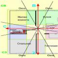
Living in a private home certainly has a number of advantages. The absence of noisy neighbors, the ability to design the building the way you want, and comparative affordability - this is what pushes residents of noisy megacities to give preference to cottage settlements. But building a house is only half the battle, because its arrangement is of great importance. Conducting communications is considered a very difficult task, which requires not only a responsible approach, but also certain skills and, of course, experience. In order for all work on the creation of water supply and sewerage in your own home to be carried out correctly, it is necessary to be guided in your work by legal documentation. Almost the entire process of creating engineering-type networks is regulated by the rules of SNIP "Water supply and sewerage". If you suddenly decide to refuse to apply the advice and instructions specified in this standard, then as a result this may become the root cause of a malfunction during operation. In addition, non-compliance with the recommendations often causes disruptions in the ecological balance of the soil of the site, as well as the ingress of fecal matter into it. And this, as you know, will entail pollution of the aquifers of the well.
According to SNiP, network engineering There are two types - external and internal. In order for each network component to work smoothly, a list of special rules and requirements was created, which are set out in document number 2.04.01-85 (for internal structures), and SNiP 3.05.04-85 (for external ones). Also remember that the creation of almost any engineering communications should be carried out exclusively by professionals in their field.
List of prescriptions for creating internal networks
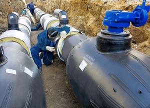
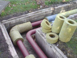
Often, internal water supply and sewerage systems are installed using structures made of polymers or metal-plastic. Depending on the specifics of the structure, as well as the volume of loads, pipes from other materials can also be used. Today, copper and steel elements are actively used for plumbing. But the first type of pipes is already fading into the background, since, according to their technical specifications, as well as cost, it is significantly inferior to polymer structures.
Systems of this type, in accordance with the regulations, can be installed in buildings of almost any purpose. It can be both private houses and institutions, both private and public, namely:
- children's;
- medical;
- food items;
- nursing home.
Speaking of private houses, we mean not only one-story buildings. SNiP allows the installation of systems in buildings with a large number of storeys.
Norms and rules for installing a cold water supply system
The internal plumbing system according to the scope of application is of three varieties:
- For supply drinking water;
- To ensure the operation of the fire fighting system;
- for industrial networks.
Internal supply network cold water consists of the following elements:
- Plumbing installations and connections to them.
- distribution networks.
- Units that are mounted at the entrance to structures.
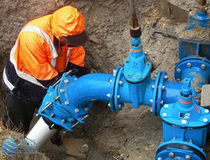
- Shutoff, control and mixing valves.
It is worth noting that it is necessary to choose the most suitable drawing for installing the internal system, taking into account the features of the structure, the number of storeys, as well as the number of devices that will be used. In addition, it is required to strictly comply with all norms and regulations established by the sanitary services.
Requirements for hot water systems
Today, in residential buildings, it is possible to create separate pipelines for supplying clean hot water, as well as water used for domestic needs. Remember: in this network, the maximum allowable pressure cannot exceed 0.45 MPa. 
Outdoor networks
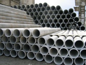
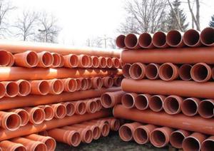
For the arrangement of sewer systems of the external type, the following pipes are used:
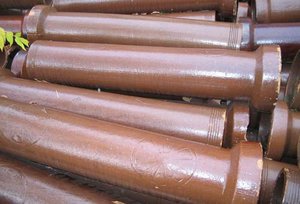
- cast iron;
- from asbestos and cement;
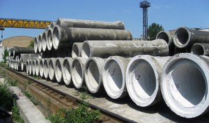
- from reinforced concrete;
- from ceramic;
- from polymers and others.
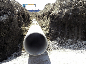
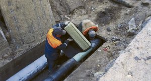
The installation of pipelines must be carried out taking into account the following facts:
- When laying pipes and installing the plumbing system, care should be taken to ensure that no groundwater and sewage enter the pipes. Before connecting pipes with fasteners, it is necessary to carefully inspect them for the presence of various blockages and, if necessary, they should be cleaned.
- The process of assembling pipelines is traditionally carried out taking into account pre-approved schemes and drawings.
- The dimensions of the laying trenches for pipe structures before installing the pipeline should be checked against those specified in the project.
- Pipes with natural circulation are placed in such a way that the socket is located towards the moving fluid.
- During installation work, it is extremely important to control the straightness of the pipes (this rule especially applies to straight sections). To control the process, you can not buy any measuring instruments, but use an ordinary mirror. Installed pipes look through, and if everything was done correctly, the reflection in the mirror will have a reflection of the circle absolutely correct form. It is necessary to check this characteristic before the trench is backfilled, as well as after.
- The current GOST establishes that the water supply and sewerage systems must be carefully processed. Otherwise, it will not be possible to prevent the formation of corrosion.
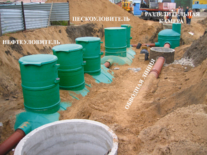
Why is it necessary to create protected areas?
To eliminate the possibility of contamination environment, it is extremely necessary to create security zones during the installation of systems.
The security zone assumes the presence of the main source of water supply, as well as highways through which the liquid moves. Conventionally, the zone is divided into 3 main belts:
- The first belt is a circle with a diameter ranging from 60 to 100 meters. In the center there is a clean water intake facility.
- The second - covers the territory that will be needed to prevent the entry of pollution into drinking water. clean water. The dimensions of this segment will have to be calculated independently, based on the specifics of the local climate and soil characteristics.
- The last belt is equipped to protect the water intake facility from third-party chemicals.
In this regard, it can be concluded that the organization of each of the three belts is mainly aimed at eliminating the possibility of contamination directly entering the source of fluid collection.
The parameters of zones of this type are strictly regulated by a set of relevant regulatory documents. In general, the functionality security zone any of the systems of the engineering plan is aimed at preventing the ingress of sewage and various contaminants into the territory used. As a rule, the development of regulatory documentation is carried out by employees of the relevant public institutions taking into account the specifics of each individual region. Traditional for systems of pressure or non-pressure type, the zone is arranged at a distance of about five meters in all directions from the outer wall of the highway. If sewerage is being built in specific regions, then the dimensions of the buffer zone must be increased by at least two times. Areas with specific operating conditions should primarily include areas with an increased level of seismic activity, weak or waterlogged soil.
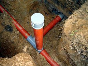
How are the pipes arranged?
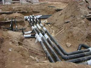
Efficient water supply involves the mutual arrangement of pipes. In the process of designing and installing absolutely any engineering type system, one should not forget that the sewerage system may well become a source of various bacteria for drinking water. Construction industry specialists have developed fairly strict rules that must be adhered to in the process of working on the system. They are fixed in SNiP and directly regulate the relative position of the water supply and sewerage mains:
- In the case of pipes located parallel, sewerage and drainage must be removed at a distance of forty centimeters.
- Within the framework of the sanitary zone of the water supply system, the construction of sewerage is strictly prohibited.
- If it is necessary to install systems whose pipes will intersect, a right angle should be arranged in the intersection object. It is completely unacceptable to cross objects at a different angle.
- Traditionally, plumbing is placed above the sewage system. At the points of intersection of the elements of the system, located at right angles, the distance between them must start from forty centimeters and grow depending on the individual parameters of the site, climate and soil.
- If it was decided to use pipes made of polymer for the organization of the water supply, they should be “dressed” in special steel casings in the intersection segments. The length of such a casing is selected in accordance with the soil at the construction site. If you have to deal with clay-type soils, the steel casing must extend at least 5 meters on each side directly from the intersection point. If the construction site is sand or other type of well-filtered soil, the length of the casing in both directions should be doubled, that is, ten meters in both directions.
- Sometimes optimal constructive solution there will be a sewerage location on top of the water supply system. In this case, the line that conducts wastewater must be dressed in a steel casing. Do not forget about the distance between the pipes in such difficult conditions. It must also be at least 40 centimeters.
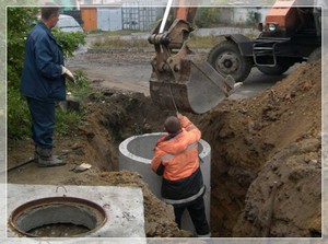
SNiP, which describes water supply and sewerage, also regulates repair work related to the restoration of the functions and operational and technical characteristics of the relevant systems. So, if it is necessary to carry out repair measures at the intersections of highways for various purposes, of course, you will have to dig a trench. Digging with an excavator is possible only until one meter remains from the surface of the bottom of the trench to the pipe. In the future, employees will have to personally get to the point of repair. In addition, in the process of self-digging, in no case should you use scrap or other tools that can harm a section of the highway.
Regulatory documentation says that between the sewer system with water supply and, in fact, the house, you need to leave a distance of one and a half meters or more.
The theoretical aspect is important
Remember that SNiP is only a source of the theoretical aspect of the installation of water supply systems. During the installation process, many factors will be revealed to you, the influence of which is obvious, but not always clear. Understanding and ability to take into account all the factors in full is a thing that will come with time, which means it will come to you mostly with experience. Meanwhile, good theoretical preparation allows you to properly understand the specifics of the upcoming construction activities. We should not forget that all communication systems at home are very closely related to each other. So, external water supply will never be effective enough, provided that the internal one functions poorly.
By designing the future system and installing it in full compliance with the requirements of regulatory documentation (SNiP), you can avoid a number of negative consequences of unprofessional installation:
- short operating period of systems;
- site pollution;
- water pollution;
- the need for frequent repairs at hard-to-reach pipe crossing points.
A competent and responsible approach to work, support from professionals and theoretical knowledge - all this minimum set, which guarantees you the successful implementation of the planned plans for the organization of sewerage and water supply systems according to SNiP.
SNiP "Water supply and sewerage": basic requirements for different types systems and their installation updated: July 2, 2017 by: Lesy
USSR STATE COMMITTEE FOR CONSTRUCTION
BUILDING REGULATIONS
Internal water supply and sewerage of buildings SNiP 2.04.01-85*
GPI Santekhproekt of Gosstroy of the USSR (Yu. N. Sargin), TsNIIEP of engineering equipment of Gosgrazhdanstroy (Candidate of Technical Sciences L. A. Shopensky), MNIITEP GlavAPU of the Moscow City Executive Committee (Candidate of Technical Sciences N. N. Chistyakov; I. B. Pokrovskaya) ), Donetsk Industrial Construction Project of the State Construction Committee of the USSR (E. M. Zaitseva), SKTB Rostrubplast of the Roskolkhozstroyobedinenie (Candidate of Technical Sciences A. Ya. Dobromyslov), Research Institute Mosstroy (Candidate of Technical Sciences Ya. B. Alesker), NPO "Stroypolymer" ( Prof. V. S. Romeiko, V. A. Ustyugov), Moscow State University of Civil Engineering (Prof. V. N. Isaev), Mosvodokanalproekt (A. S. Verbitsky).
INTRODUCED GPI Santekhproekt Gosstroy USSR.
PREPARED FOR APPROVAL by the Glavtekhnormirovaniye of the Gosstroy of the USSR (Gosstroy of the USSR) - B.V. Tambovtsev, V.A. Glukharev.
AGREED BY the Ministry of Health of the USSR, GUPO of the Ministry of Internal Affairs of the USSR.
SNiP 2.04.01-85* is a reissue of SNiP 2.04.01-85 with amendments No. 1, 2, approved by the Decree of the USSR Gosstroy of November 28, 1991 No. 20, of July 11, 1996 No. 18-46 and amendments introduced by letter Gosstroy of the USSR dated May 6, 1987 No. ACh-2358-8.
Items and tables that have been amended are marked in these building codes and rules with an asterisk.
When using a regulatory document, one should take into account the approved changes in building codes and regulations and state standards published in the Bulletin of Construction Equipment magazine and the State Standards information index.
1. General Provisions
1.1 .These standards apply to the design of internal cold and hot water supply systems, sewerage and drains under construction and reconstructed. .
1.2. When designing systems for internal cold and hot water supply, sewerage and drains, it is necessary to comply with the requirements of other regulatory documents approved or agreed by the Ministry of Construction of Russia.
1 . 3. These standards do not apply to the design of:
fire water supply systems of enterprises producing or storing explosive, flammable and combustible substances, as well as other objects, the requirements for the internal fire water supply of which are established by the relevant regulatory documents;
automatic fire extinguishing systems;
thermal points;
hot water treatment plants;
hot water supply systems supplying water for the technological needs of industrial enterprises (including medical procedures) and water supply systems within the technological equipment;
systems of special industrial water supply (deionized water, deep cooling, etc.).
1.4. Internal water supply - a system of pipelines and devices that provides water supply to sanitary appliances, fire hydrants and technological equipment, serving one building or a group of buildings and structures and having a common water meter from the water supply network of a settlement or industrial enterprise.
In the case of water supply from the system for external fire extinguishing, the design of pipelines laid outside buildings must be carried out in accordance with SNiP 2.04.02-84 *.
Internal sewerage - a system of pipelines and devices in a volume limited by the outer surfaces of the enclosing structures and outlets to the first manhole, providing wastewater from sanitary appliances and process equipment and, if necessary, local treatment facilities, as well as rain and melt water to the sewerage network the corresponding purpose of the settlement or industrial enterprise.
Notes: 1. Hot water preparation should be provided at the units in accordance with the guidelines for the design of heating points and heating units.
2. Installations for local wastewater treatment should be designed in accordance with SNiP 2.04.03-85 and departmental building codes.
1.5. In all types of buildings erected in sewered areas, internal water supply and sewerage systems should be provided.
In non-sewered areas of settlements, internal water supply and sewerage systems with the installation of local sewage treatment facilities must be provided in residential buildings with a height of more than two floors, hotels. nursing homes (in rural areas), hospitals, maternity hospitals, polyclinics, outpatient clinics, dispensaries, sanitary and epidemiological stations, sanatoriums, rest homes, boarding houses, pioneer camps, nurseries, kindergartens, boarding schools, educational institutions, secondary schools, cinemas, clubs , public catering establishments, sports facilities, baths and laundries.
Notes: 1. In industrial and auxiliary buildings, internal water supply and sewage systems may not be provided in cases where the enterprise does not have a centralized water supply system and the number of employees is no more than 25 people. in shift.
2. In buildings equipped with internal domestic drinking or industrial water supply, it is necessary to provide an internal sewerage system.
1.6. In non-sewered areas of settlements, it is allowed to equip the following buildings (structures) with backlash closets or cesspools (without plumbing inlets):
production and auxiliary buildings of industrial enterprises with the number of employees up to 25 people. in shift;
residential buildings with a height of 1-2 floors;
dormitories with a height of 1-2 floors for no more than 50 people;
pioneer camps for no more than 240 places, used only in the summer;
type I clubs;
open planar sports facilities;
enterprises Catering no more than 25 seats.
Note. Backlash closets are allowed to be provided when designing buildings for I-III climatic regions.
1.7 . The need for internal drains is established by the architectural and construction part of the project.
1.8. Pipes, fittings, equipment and materials used in the construction of internal systems of cold and hot water supply, sewerage and drains must comply with the requirements of these norms, state standards, norms and specifications approved in the prescribed manner.
When transporting and storing drinking water, pipes, materials and anti-corrosion coatings approved by the Glavsanepidnadzor of Russia for use in the practice of drinking water supply should be used.
1.9. The main technical decisions taken in the projects and the sequence of their implementation must be justified by comparing the indicators of possible options. Technical and economic calculations should be carried out for those options, the advantages (disadvantages) of which cannot be established without calculation.
The optimal calculation option is determined by the smallest value of the reduced costs, taking into account the reduction in the consumption of material resources, labor costs, electricity and fuel.
1.10. When designing, it is necessary to provide for the use of progressive technical solutions and methods of work: mechanization of labor-intensive work, automation of technological processes and the maximum industrialization of construction and installation work through the use of prefabricated structures, standard and standard products and parts manufactured in factories and procurement workshops.
1.11. The main letter designations adopted in these standards are given in mandatory Appendix 1.
For device outdoor sewerage and plumbing assign initial design, approve layouts and further development. Workflow projects are typically developed concurrently on water supply network and sewage, while calculating the optimal balance of water consumption of the object and filling sewer facilities for the treatment and disposal of used effluents.
The arrangement of external water supply and sewerage at large facilities is provided so that it is possible to connect them as much as possible with other treatment facilities and existing pipelines. The possibility of using treated wastewater for irrigation and watering, as well as for filling production processes with the necessary process water is necessarily considered.
In addition to design developments, when building centralized highways, reconstructing and expanding existing networks, one should be guided by the provisions of SNiP, take into account other rules and regulations, standards and other departmental documents that have been approved in accordance with the norms of SNiP 1.01.01–1983.
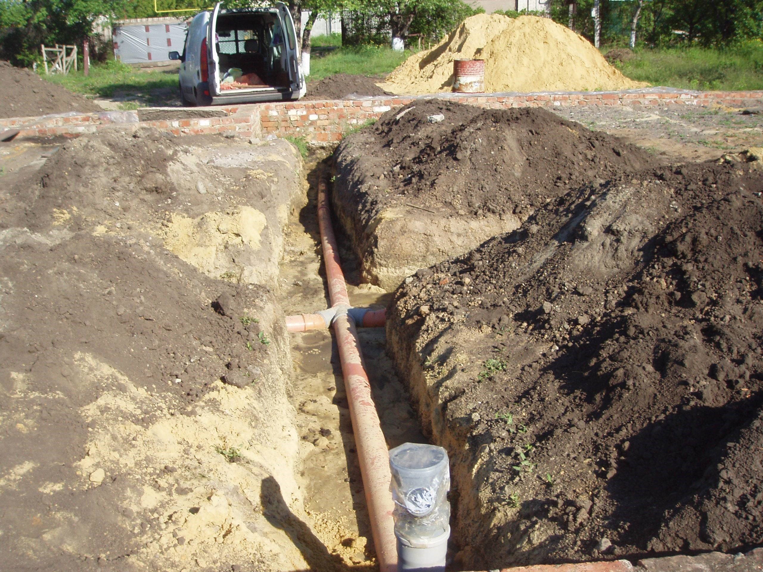
For the acceptance of work into operation at the end of construction and there are requirements set out in SNiP 3.01.04–1987. Digging trenches, excavation, backfilling after laying the pipeline is regulated by SNiP 3.02.01–1987.
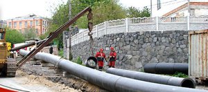
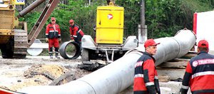
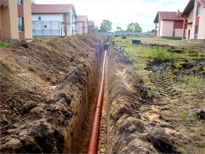
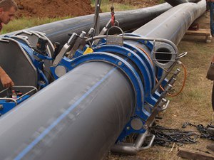
Laying of external pipelines
 To prevent damage to the anti-corrosion layer of the top coating of pipes and assembled finished sections, sparing grips made of soft materials are used that cannot harm the surface layer.
When laying out and connecting pipes intended for the supply of drinking water and hygiene procedures, they try prevent any external sewage from entering and other surface liquids. All pipes and fittings must be cleaned internally before being installed in the installation position.
Work on the installation of external pipelines must be detailed in the work book, which describes the volumes performed every day, indicating compliance with the project, the depth of the foundation, the degree of strengthening of the walls of the trench.
 If a slope of the pipeline with non-pressure movement of liquid is provided, then pipes with welded sockets are laid along it with a wide part upwards. By doing straight sections from one well to another using a mirror check the view to the light. Such checks are carried out until backfill, while the displayed gap should be a round outline. A horizontal deviation of no more than 5 cm in each direction is allowed. There should be no vertical deviations.
Small deviations from the design axis of external pipelines under pressure are allowed, which should not be more than 10 cm in plan, and the marks of non-pressure trays should not exceed 0.5 cm. in accordance with SNiP, and if special conditions are required, they are indicated in the working drafts.
When laying the pipeline along a slight curvature of the route, products with welded sockets should be used and rubber gaskets should be installed. WITH Turning movement is allowed only 2º for pipes with a diameter of up to 60 cm and 1º when laying with a diameter of more than 60 cm. The installation of a pipeline in rough terrain is regulated by the provisions and rules of SNiP III-42–1980.
 The connections of the socket pipes in straight sections are made so that the equal width of the socket gap is centered along the diameter for grouting. During breaks in laying, the ends of the pipes and various mounting holes are buried with plugs and plugs. When installing in frosty conditions, the rubber seals are first defrosted.
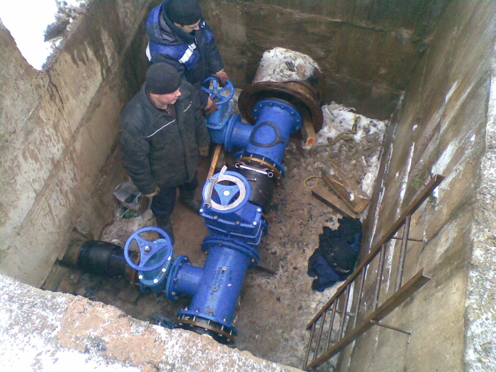
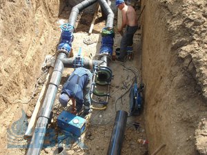
Joint sealants and sealing materials are used by those that are developed and laid down in the project. When connecting with flanges, several rules are observed:
- flange connections are placed strictly perpendicular to the central pipe axis;
- when installing bolts, their heads are placed on one side, the hardware is strengthened gradually according to the principle of a cross;
- the planes of the flanges must be even, without distortions, their alignment with the help of gaskets is not allowed;
- all adjacent welding joints are performed after the installation of the flange.
 If the wall of the pit is used as a support, then its structure should not be disturbed by digging. Slots obtained from the installation of an external pipeline on prefabricated supports, must be sealed with concrete or cement mortar. The insulation of steel and reinforced concrete elements of the pipeline is carried out in accordance with the project or the provisions of SNiP 3.04.03-1985.
All work performed, which will be hidden by a layer of soil, is necessarily reflected in the acts for hidden work. Subject to verification:
- preparation and arrangement of the base;
- installation of stops;
- fixed gaps of butt joints, method of sealing;
- construction and installation of wells;
- implementation of corrosion protection;
- a method of isolating pipe passages through the side walls of wells;
- trench backfilling and ramming method.
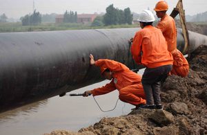
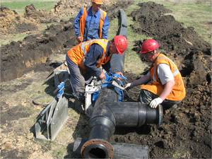
The device of external pipelines from steels
 Before starting welding work, the joints are cleaned of contamination, the conformity of the geometric dimensions of the edges is checked, and they are cleaned until a shine appears. After welding is completed all damaged areas must be insulated according to old scheme according to the design guidelines.
In order to weld two pipes with a longitudinal or spiral assembly seam, the ends of the pipes should be positioned so that the offset of the joints is no more than 10 cm. If factory products with a longitudinal joint are used, then alignment does not play a role. Transverse welding seams have:
- no closer than 20 cm from the edge of the outer pipeline;
- no closer than 30 cm from the enclosing surface of the main structure, passing the pipeline or from the case edge;
- no closer than 10 cm from the welded branch pipe.
 When installing the pipeline, centralizers are used, it is allowed to straighten dents on the walls up to 3.5% of the diameter. Curves with a large size are cut out of the route. The nicks at the ends of the pipes more than 0.5 cm are cut off with a section of the pipe.
Welders are allowed to perform welding with documents authorizing welding work, who have passed the certification of welders according to the rules of the State Technical Supervision Service. To recognize the master at a distance of 40 cm from the joint on the visible side a red-hot personal brand of each welder is put.
 If welding is used in several layers, then each seam must be cleaned from slag and metal splashes before the next one is applied. Those areas on which a seam with craters and shells is applied are cut down to the base metal, and the cracks in the seam are boiled a second time. Outdoors, contact with workplace wet precipitation and gusts of wind. When conducting a control review of welding, the following is carried out:
- control over each welding and pipeline assembly operation according to SNiP 3.01.01–1985;
- checking the continuity of the welded joint and detecting defects by radiographic control method (X-ray or ultrasound).
 All received joints are subjected to external inspection. When constructing a pipeline from pipes over 100 cm measure the outer and inner diameters. Before starting the inspection, the surface on both sides of the seam is cleaned of slag and metal splashes, scale.
If an external examination did not reveal metal cracks in the seam and the adjacent area, deviations from the dimensions and the required shape, sagging, burns and sagging with inside, then the quality of welding is considered satisfactory. Unsatisfactory seams are to be knocked down and performed again.
Welding quality is checked by X-ray and ultrasound at a system pressure of up to 10 atmospheres, in an amount of at least 2%, but at least one weld per welder, up to 20 atmospheres, in a volume of 5%, but at least two welds per welder. An increase in pressure above 20 atmospheres increases the amount of welding material to be checked up to three seams per welding worker. Welded joints selected for control are checked under the control of the customer, who notes in the work log information about the location of the joint and the name of the welder.
If, when determining the quality of the seam, fistulas, cracks, poorly welded areas are found, then such a seam is rejected, redone and a second quality control is performed. When viewing with physical devices, elements of marriage are allowed:
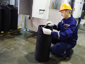
Installation of cast iron pipes
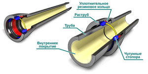 Cast iron pipes are exposed and connected by means of socket joints, which are compacted with resin hemp or strands impregnated with bitumen. On top they arrange a lock made of asbestos cement. If the pipes are made without a socket, then they are connected using rubber cuffs, which are supplied in parallel with the pipes. The composition of the mixture components is described in the project, the name and quality of the sealant are also indicated there.
For control correct installation gap for the stop surface of the socket and the pipe end to be connected is performed slot for pipes with a diameter of up to 30 cm, adopted 5 mm, and for a larger diameter, this figure is equal to a size of up to 10 mm.
Construction of external pipelines from asbestos cement
 Before making the connection, marks should be made on the end of the pipe, indicating the position of the coupling before installation and after the finished mounted joint. Connection of asbestos pipes with metal fittings or sections of steel pipes are produced by cast iron fittings or steel joints using rubber sealing rings.
The quality of sealing each seam is checked after connection, while paying attention to the correct installation of the rubber bands and the location of the couplings, as well as the uniformity of the tightening of the bolts.
Laying of concrete and reinforced concrete sections of the pipeline
For reinforced concrete pipes, the gap between the socket stop and the end is performed in millimeters:
The joints of pipes placed on the site without standard seals are sealed with tarred hemp or a strand impregnated with bitumen. The lock is treated with an asbestos-cement mixture or special sealants specified in the project with a description of the required embedment depth. Pipelines over 100 cm are closed at the joints cement mortar of the brand defined in the project. If the brand is not separately indicated in the diagrams and documents, then they are sealed with a composition solution of 7.5.
The sealing of joints with folds when arranging a non-pressure version for pipes made of concrete with smooth ends is carried out strictly according to the instructions of the project. When arranging joints of reinforced concrete products, metal inserts and shaped elements according to the project.
Ceramic outdoor piping
 The value of the end gap is taken for pipes with a diameter of up to 30 cm - 6–7 mm, bigger size- up to 10 mm. The joints are insulated with tarred hemp or bitumen in contact with the strand and further coating with cement mortar, bituminous mastic or sealants. Suitable for use with asphalt mix, if the temperature of the water flow does not exceed 40ºС, and it does not contain chemical wastes that dissolve bitumen. The pipes entering the well or chambers should be sealed in such a way that water tightness and tightness of the joints are ensured.
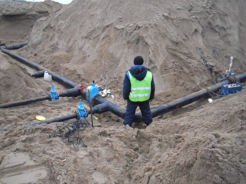
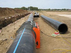
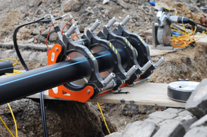
Installation of lightweight plastic pipelines
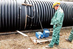
Pipes are made of low and high pressure polyethylene, which are connected to each other and insert elements by butt-welding the ends or using socket pipes. Only elements of the same material are welded, and the connection of different materials is not allowed.
 For the performance of work, people who have the right to weld, confirmed by documents, are allowed. Ensuring the efficiency of the process, various installations are used, providing compliance with the specified technology parameters. Welding polyethylene pipes allowed at a temperature not lower than 10ºС frost, moisture and dust ingress to the welding work area is not allowed.
It is allowed, according to the norms of SNiP, to glue the same type of pipes made of polyethylene using a special glue, which is used when installing rubber cuffs that come to the facility along with the products. Do not expose mechanical stress joints within 20 minutes, and hydraulic effects can take place only after a day from the moment of gluing. The ambient temperature should not exceed 35ºС and be not lower than 5ºС, gluing is carried out in a place protected from rain and wind.
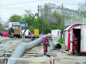
The device for the external passage of the pipeline through obstacles
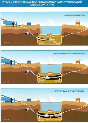 Fluid supply lines often encounter natural obstacles on their way: rivers, lakes, ravines, quarries. In places of previously laid roads, tram and train tracks, subways also have to equip specialized crossing points. To work on the construction of transitions workers of specialized organizations are allowed, which have a license to puncture under roads and other places.
The procedure for arranging passage under roads and natural barriers is necessarily described in detail in the project with the preparation of special drawings and takes place with constant technical supervision of each stage of the implementation. At the same time, special attention is paid to the installation of through-hole cases and pipeline marks.
Permissible deviations are provided for the height marks of the cases:
- with slope hold in accordance with the project, the vertical deviation can be no more than 0.6% of the size of the case for non-pressure and 1% pressure lines;
- offset is allowed in the plan only 1% of the shell size of systems without pressure and 1.5% for pressure options.
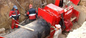
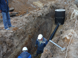
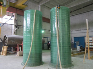
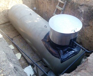
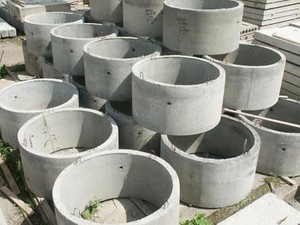
Rules for the installation of collecting tanks
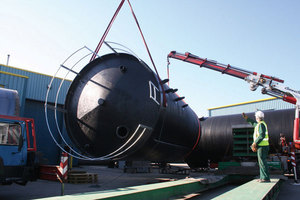 To facilitate compliance with the rules for arranging prefabricated containers made of concrete and reinforced concrete, one should be guided by the provisions specified in SNiP 3.03.01–1987. The backfilling of the earth is done by mechanisms after the completion of the laying of pipelines to and from the treatment tanks. A preliminary test is carried out by supplying working pressure to the line, but only after the concrete structures have gained all the prescribed strength.
Installation drainage systems and their distribution units is carried out after testing the mounted container for tightness. Drilling holes in pipelines is carried out according to the terms of the project. Deviations from the design size of the holes should not exceed 1–3 mm. Offset from the design position of the axes of caps, couplings is allowed only 4 mm, and in height should not be more than the design mark.
The edge marks of the trays and drains are made according to the liquid level and are guided by the project data. When punching triangular overflows, the bottom of the hole should not be 3 mm higher or lower than the design. The line of trays and gutters should not have sections with an inclination opposite to the movement of drains, on the surface of the channel there should not be bumps and build-ups that prevent the natural flow of water.
 All filters with filling are added to the design of the treatment plant only after the completion of hydraulic testing activities, and during repair work - after flushing and cleaning the supply pipelines and locking devices.
The filter components used to pass the liquid are selected subject to the requirements of SNiP 2.04.02–1984. The descriptions indicate the thickness of the filter layer, the deviation from the dimensions of which is allowed within no more than 2 cm.
Welding work is completed before the installation of the wooden structural components of the treatment plant.
Technology for the construction of water supply and sewerage in difficult climatic conditions
 Special points that must be taken into account when constructing highways in difficult natural conditions are described in a separate section in the project. Temporary water supply pipelines are laid above the ground, and the requirements are observed as when carrying out work on the installation of a permanent branch.
The construction of water supply and sewerage on frozen soils, as a rule, is carried out with negative figures air temperature. The provisions of SNiP provide for the requirement preserve the frozen soil of the base in its original form. The same applies to construction on frozen ground, but already at temperatures above 0ºС, it is impossible to change the soil parameters adopted in the basis of the project.
If soils abundantly saturated with ice inclusions enter the development, they are thawed to the design freezing depth and compacted. Sometimes it is planned to replace the soil with compacted thawed masses. The movement of auxiliary and main vehicles is carried out along special access roads, which are carried out in strict accordance with the working drawings.
 Construction of water and sewer mains in the conditions of the area with high seismic hazard is produced according to the standard terrain method, but additional measures are taken to protect buildings from destruction during tremors.
Docking sections are performed by electric arc welding, and their verification is carried out by 100% by the method of physical control. Plasticizers are added to cement joint and insulating mortars to reduce damage. Measures to reduce the impact on structures of a seismic situation are mandatory recorded in the work log and acts for work hidden by the ground.
When backfilling trenches, the internal cleanliness of expansion joints is maintained. The seam gap must be continuous and cleared of layers of earth, concrete splashes and influx of mortar along the entire length from the sole of the base to the top of the aerial part. Remains of formwork and shields are removed from them.
 Works on the device of expansion and expansion joints, gaps for sliding, reinforcement, installation of hinged fasteners and spacers, arrangement of the passage of pipes through hard surfaces must be certified by supporting documents.
When laying water supply and sewerage in a swampy area, before laying the pipe in a trench, liquid is pumped out of it. Sometimes in the description design work laying into a water-filled trench, but in this case, the methods specified in the documents must be followed to prevent the pipe from surfacing. It is necessary to move such pipes by swimming with necessarily muffled ends.
The construction of a water supply and sewerage route on the surface of the dam is permitted only when the soil is compacted to the design state, which is verified by research. When laying pipes on soil with a high coefficient of subsidence, in places where supports for connections are installed, soils are also compacted using internal vibrators.
Test activities
Pipelines with working pressure
 For some systems, the work plan specifies how the test is to be carried out. If there is no such data, then verification is being done in a standard way
, which consists in testing for tightness and strength by the hydraulic method. In some cases, the pneumatic method is allowed:
For some systems, the work plan specifies how the test is to be carried out. If there is no such data, then verification is being done in a standard way
, which consists in testing for tightness and strength by the hydraulic method. In some cases, the pneumatic method is allowed:
- for underground pipelines made of asbestos-cement, cast iron and reinforced concrete pipes at a design pressure of not more than 5 atmospheres;
- for pipelines in the soil with a design pressure of not more than 16 atmospheres made of steel;
- ground steel lines with a pressure of not more than 0.3 atmospheres.
All pipelines without exception are tested twice. The first stage involves a control test by a construction company without an invitation from a customer representative. This action documented by a special act, the form of which is accepted in the construction company. The test is carried out by backfilling the trench to half the level of the pipe. In this case, all connecting joints remain open for visual inspection. Methods for such a preliminary test are regulated in the provisions of SNiP 3.02.01–1987.
The last final acceptance is carried out after the final backfilling of the pipeline and compaction of the soil. At this stage, a representative of the customer is present, and all actions are formalized by a standard act for such a case.
If the pipeline is laid in land conditions that allow visual inspection of the system, then no initial check. A preliminary check is not carried out in crowded conditions and if immediate backfilling is required, for example, in case of severe frosts.
![]() When arranging a water supply and sewerage route through natural obstacles, the test is carried out for the first time during assembly on site after the pipes are connected, but before anti-corrosion treatment is performed. The second stage involves testing the pipes laid in the working position without digging into the soil. The results of the check are reflected in the corresponding act.
When arranging a water supply and sewerage route through natural obstacles, the test is carried out for the first time during assembly on site after the pipes are connected, but before anti-corrosion treatment is performed. The second stage involves testing the pipes laid in the working position without digging into the soil. The results of the check are reflected in the corresponding act.
Highways laid in places under railways and highways, they are checked for the first time when laying in a working position, but already in a protective casing. The cavities between the walls of the casing and the pipe are not filled. The second time is tested after complete backfilling and compaction of the soil.
The size of the test pressure and the value of the calculated pressure of the liquid in the line are indicated in the provisions of the working draft, guided by the data of SNiP 2.04.02–1984.
Reinforced concrete, asbestos-cement, cast iron and steel lines are tested in sections 1 km long at a time. It is permitted to increase the size of the test area beyond 1 km if the volume of pumped water is calculated as for a length of 1 km. Water pipelines made of polystyrene, polyethylene, polyvinyl chloride are checked sequentially in sections of no more than 0.5 km. If the volume of pumped liquid is the same as for a section of 0.5 km, then it is allowed to take a length of 1 km for testing. If the project for the production of works does not contain data on the value of the allowable pressure for testing, then it is calculated according to special tables.
Before the test begins, the following work must first be completed:
 The specialist in charge of the test is issued a permit for carrying out high-risk work, indicating in it the coordinates and dimensions of the space being checked. This document is filled out according to the established pattern, which is determined by the norms of SNiP III-4-1980.
Measuring instruments in the test process are pressure gauges, which must meet certain parameters:
- accuracy class should not be lower than 1.5;
- the diameter of the device (case) is not less than 16 cm;
- the scale of the instrument should be 1/3 higher than the limit indication of the test pressure.
 The measurement of the volume of water used during the test is carried out with measuring containers or temporary water meters are installed, which are certified in the standard manner.
The arrival of water and filling the test section of the highway should be carried out with the intensity specified in the project, which in standard cases is:
- for pipes with a diameter of up to 40 cm - no more than 5 m3 per hour;
- for pipes with a diameter of up to 60 cm - no more than 10 m3 per hour;
- for pipes with a diameter of up to 100 cm - no more than 15 m3 per hour;
- for pipes with a diameter of up to 110 cm - no more than 20 m3 per hour.
Acceptance of the pressure line using hydraulics begins after filling the trench with soil in accordance with SNiP 3.02.01–1987. Before this, the system is filled with water and kept in a filled state. Reinforced concrete pipelines are kept for 72 hours, of which 12 hours are pressurized within the design value. Asbestos-cement and cast iron pipes are checked for 24 hours, half of the time is under pressure. Pipelines made of steel and polyethylene are not pre-filled with water; such a check is not provided for them. In the case of filling with liquid, the inspection time is counted from the moment the trench is filled with earth.
 The network is recognized as having passed the test if the volume of the lost liquid does not exceed the allowable flow rate of pumped water for a test section of 1 km. If the water flow rate is more than specified, the main is not recognized as serviceable, and measures are taken to identify defects in the desired area. After the leak is eliminated, the test is repeated.
Data on these parameters are given in special test tables. For cast iron pipes connected to each other with rubber rings, the allowable value is multiplied by a factor of 0.75. If the length of the desired gap is less than 1 km, then the allowable volume of pumped liquid is brought to a different value by multiplying it by the actual length of the pipeline.
For pipes made of polypropylene, polyethylene, welded together, and for sections of glued PVC elements, the allowable value of the flow rate of the pumped liquid is taken as for pipelines made of steels equal in diameter. PVC pipes connected rubber seals, are calculated for the flow rate of pumped water as for cast-iron elements of equal diameter.
The amount of hydraulic pressure for testing the pipeline for tightness and strength is usually indicated in the description of the working project. If there is no such data in the documents, then they take the standard value:
To check the steel line, before starting the test for strength and tightness, air is pumped into it. It must be in the pipeline section for a certain time to equalize the temperature of the soil and air mass. The time depends on the diameter of the pipes:
- pipe diameter up to 30 cm is subject to exposure for 2 hours;
- from 30 cm to 60 cm withstand 4 hours;
- diameter from 60 cm to 90 cm requires exposure to 8 hours;
- from 90 cm to 120 cm the temperature levels off within 16 hours;
- pipes from 120 cm to 140 cm in diameter withstand 24 hours;
- the line with a diameter of more than 140 cm is filled with air for 32 hours.
 For all pipe diameters, it is recommended to apply test pneumatic pressure for a period of 30 minutes, which is achieved by additional pumping of air mass. To inspect the pipeline in order to identify defects, the pressure is reduced. Steel pipes are inspected at a pressure of 0.3 MPa, reinforced concrete, cast iron and steel - with readings of 0.1 MPa. Connection defects will be indicated by bubbles appearing in the connecting places and the sound of passing air.
The elimination of leaks is carried out at zero pressure, after which the pipeline section is retested. The pipeline is considered accepted for operation if the inspection does not reveal any violation of the integrity of the pipe and weld joints.
Checking non-pressure pipelines
 Pipelines that will be operated without pressure are taken in two stages. The initial test is carried out before backfilling., and the final check is carried out after the implementation of the shelter in one of the ways, which is determined by the working draft:
the volume of liquid added to the desired section of the pipeline, laid in dry soil or in wet soil, is measured, if the mark ground water at the highest well is below the earth's surface by more than 0.5 of the depth of the laid pipes, measuring from the shelyga to the hatch;
the volume of fluid inflow into the line laid in wet soil is measured if the groundwater level is greater than 0.5 of the depth indicator.
Wells, in which moisture insulation is located inside, are checked for tightness by measuring the volume of added liquid, and structures in which waterproofing is provided outside, by measuring the volume of water inflow.
Those well designs that are equipped with waterproof walls and are insulated from moisture inside and out, tested by determining the volume of moisture inflow or measuring the added water at the same time as checking the line or a separate stage. If the well, according to the project, does not provide for waterproofing outside and inside, and the walls are made of permeable materials, then a check for tightness and strength is not provided.
 The tightness test is carried out on sections of the pipeline between adjacent wells. Sometimes the required amount of water for testing is not available or its supply is difficult, then it is allowed to test sample areas determined by the customer representative. According to the norms, with a length of the main line up to 5 km, several sections are checked, and if the length of the pipeline is more than 5 km, then several sections are tested so that their total length is 30% of the length of the route. If the test result of at least one of the wells is unsatisfactory, the entire pipeline is tested.
The value of water pressure must be determined in the working design. If there is no such data in the documents, then this indicator is determined by the volume of liquid excess in a well or riser above the main line or above the ground liquid mark, if it is above the device. For ceramic, reinforced concrete, concrete pipelines, this indicator is standardized to a value of 0.04 MPa.
The hydraulic pressure in the line is created by filling the riser located at the top with liquid, or by filling the upper well with moisture, if it is intended to be tested.
The first stage of the strength test is carried out with the pipeline open for 30 minutes. To do this, constantly add liquid to the well or riser so that the water level does not drop by more than 20 cm.
 The pipeline and wells are considered to have passed the tightness test if no areas of fluid leakage are detected during visual inspection. Allowed droplet formation at pipe joints, not merging into one stream, if the project does not provide for requirements for increased tightness of the pipeline. In this case, the total area of areas of misting with drops should not exceed 5% of the area of pipes in the section being checked.
The final acceptance test for tightness begins after filling with water and holding in this state. For wells and pipelines made of reinforced concrete and protected from moisture from the inside and outside, the exposure time is 72 hours, and for all other materials - 24 hours.
The tightness of the pipeline covered with soil during final acceptance is carried out in one of the following ways:
- first method allows you to determine in the upper well the volume of water added to the riser for 30 minutes of time so that the liquid level in the structure under test does not drop by more than 20 cm;
- second way involves measuring in the lower well the volume of ground moisture seeping into the well.
 A section of the main line is considered to have passed acceptance for tightness if the volume of added water in the first method and the influx of liquid in the second method does not exceed the norms presented in special tables, about which an acceptance certificate is drawn up in a mandatory form.
If the test time increases and is more than 30 minutes, then the indicator of the allowable volume of liquid, taken from the table, also increases proportionally.
Pipelines made of reinforced concrete with rubber seals at the joints allow the volume of added liquid or water inflow, indicated in the table, multiplied by a factor of 0.7.
To determine the allowable inflow rate or the volume of liquid through the enclosing structures in the well per 1 m of its depth, this value should be taken for pipes of the same material and equal diameter.
Rainwater drainage is checked according to the rules intended for testing free-flow pipelines preliminary and final testing, if specified in the working draft document.
 If the line is made of non-pressure roller or socket reinforced concrete elements with a diameter of more than 160 cm, which are designed by the project for lines with a working pressure of up to 0.05 MPa with external and internal waterproofing provided for by the project, they are checked for operability by a hydraulic test with a pressure specified in the project.
Testing of capacitive structures
 Collecting tanks made of concrete are subject to inspection only after the laid concrete reaches the strength provided for in the project. Before hydraulic testing of capacitive structures for tightness and strength, they are thoroughly cleaned from the influx of solution and debris. Isolation from moisture and backfilling of the trench with soil is carried out only after positive results of the hydraulic test, unless other conditions are prescribed in the working design of the work.
Prior to the start of work on hydraulic testing, the collecting container is filled with liquid in two stages. The first one involves pouring water to a height of 1 m and keeping it in the chamber for one day. The second stage replenishes the capacity to the mark of the design top. After that, the liquid is kept in the tank for at least 72 hours.
The collection container is considered to have passed the test if the outflow of water in it is not more than three liters per 1 m2 wet bottom and walls. Examine the seams, walls and base for water leakage. Permissible fogging and darkening of some places. If the container is open, then the effect of liquid evaporation from the water surface is additionally taken into account.
If water leaks are found on the walls and seams or wet soil in the base, the container is considered to have failed the test, even if the amount of liquid lost does not exceed the allowable limits. In such cases, all areas with defects are noted, which are then repaired. After carrying out work to eliminate the shortcomings, the collecting capacity is tested again.
When carrying out a leak test on containers that are supposed to contain aggressive liquids, the slightest leak is not allowed. The test is carried out before the application of the anti-corrosion layer.
 All prefabricated and monolithic filter channels and lighting contact chambers are subject to hydraulic checks with the design pressure specified in the working draft of the work. They are recognized as having passed the hydraulics test if, during visual inspection, no fluid leaks are detected in the side surfaces of the filter channels and above them, and the value of the control test pressure is not reduced by more than 0.002 MPa.
When testing the collection tank of the cooling tower and during its hydraulic check, darkening of places and even slight fogging of them is not allowed. Sumps and potable water containers pass hydraulic test after providing overlap, it is carried out in accordance with the norms and requirements of standard rules. Drinking containers are subjected to an additional test for vacuum and overpressure by excess air pressure in the amount of 0.0008 MPa for half an hour. They are considered fit if the pressure index decreases by no more than 0.0002 MPa, unless other requirements are specified in the design documents.
 Drainage and distribution caps of filter channels are tested for delivering fluid flow at a rate of 5–8 liters per second and air flow at a speed of 20 liters per second. This feed is carried out three times lasting up to 10 minutes. Caps with detected defects are replaced and re-checked.
The mains of the water supply and sewerage, before carrying out the acceptance measures, are mandatory washed and disinfected with a chlorine solution with further washing. Control chemical and bacteriological samples are taken, washing is carried out to positive results that meet the standard requirements of GOST and the instructions of the Ministry of Health for the control of drinking water disinfection and disinfection of water supply.
Measures for disinfection and flushing of pipes and structures of the utility and drinking main are carried out by a construction organization that lays pipelines with the participation of the customer and the controlling organization sanitary and epidemiological operational service in the standard manner set out in the relevant instructions. The results of the work carried out are recorded in an act of washing and disinfection in a standard form, which contains the signatures of all representatives of the executive and supervisory services.
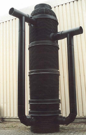
Structures on the main water supply and sewerage
Connections, bends and piping depth
 All docking points, turns of the route on the collectors are arranged in wells. The turning radius of the tray is taken not less than the diameter of the element in collectors with a size of 120 cm. Collectors with large diameters are arranged with a turn of at least 5 pipe diameters, while inspection wells are necessarily arranged at the beginning and end of the bend.
The angle of connection of the outlet pipe is taken not less than a straight one. If the connection is made with a height difference, then the angle between the connected route and the outgoing route is allowed to be of any size.
Docking of pipes of different diameters is carried out along the shelyg or at the level of the calculated liquid height. To determine the smallest pipe laying depth, a thermal calculation is performed or the standard laying depth in the working area is taken into account.
If it is impossible to perform calculations or there is no data on the depth of laying in a given area, then standard conditions are accepted. Pipeline with a diameter of less than 50 cm they are laid to a height of 30 cm, and pipes of larger diameter are laid to a depth that exceeds the freezing point of the soil by half a meter. This distance may not be less than 70 cm from the top of the pipe, starting from the ground surface or grade level, to prevent crushing by machines.
The maximum laying depth is determined by special calculations, which take into account the category of soil, the material of the pipes and their size, as well as the method of laying. Ready data are indicated in the project for the production of works.
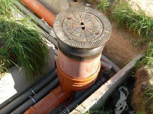
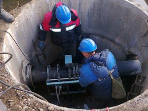
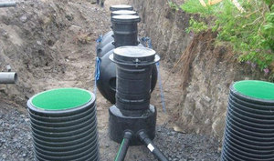
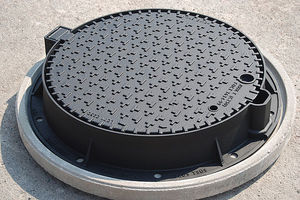
Construction of manholes
Manholes along the highway suit:
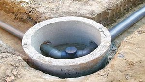
The dimensions of rectangular wells or sewer chambers in the plan are provided depending on the diameter of the pipes. Pipelines up to 60 cm in diameter require a size of 100 X 100 cm. Lines with a pipe diameter of more than 70 cm are equipped with wells 120 X 150 cm.
Round wells are arranged on tracks with a diameter of up to 60 cm and a size of 100 cm, with a diameter of up to 70 cm they put decks of 125 cm, more than 120 cm in diameter require a well of 200 cm.
 The dimensions of the rotary wells are calculated based on their design conditions for placing receiving and intermediate trays in them. On routes with a diameter of not more than 15 cm and a pipe laying depth of up to 1.2 m it is allowed to install wells, small in size, up to 60 cm in size. They are intended only for lowering cleaning mechanisms, people are not lowered.
In height, working wells are made to a height of 1.8 m (from the platform to the cover), if the working height of the well according to the project is less than 1.2 m, then their width is made from 30 to 100 cm. Shelves and platforms for manholes are arranged at the height of the upper surface pipes of the largest diameter.
 On highways of elements with a diameter of 70 cm or more, a working area is arranged in front and a shelf of at least 10 cm in size on the other side of the tray. In pipelines with a diameter of more than 200 cm, the working platform is performed on consoles, with an open tray of at least 200 X 200 cm.
For preventive maintenance of trays and descent of people, hinged ladders are provided in the working part of the well, which can be stationary or removable. Be sure to arrange a fence of the site for work to a height of one meter.
rain wells
Rain sewer wells are arranged in terms of dimensions on pipelines from 60 to 70 cm with a diameter of 1 m, and from 70 cm or more they are made rectangular in size 1 m X 1 m or round with a diameter equal to a large pipe, but not less than 1 m.
The height of wells on pipelines with a diameter of 70 cm to 140 cm depends on the largest tray, on highways with a diameter of more than 150 cm work sites are not included. Shelves in wells are arranged only in pipelines no more than 90 cm at the level of ½ half of the largest pipe.
The standard width of the manhole neck for all sizes is assumed to be 70 cm in diameter, it should allow lowering the equipment for cleaning the route on bends and straight sections.
Hatches are installed at the level of the road of the carriageway with ideal coverage. On lawns and in the green zone, the cover should be 7 cm above the surface, and in unequipped and undeveloped areas, the hatch cover mark is 20 cm from the ground. To prevent unauthorized entry hatches satisfied with locking devices. The design of the hatch must be strong and withstand the load from passing vehicles or other loads and allow the free entry of maintenance personnel.
If in the place of the well device high level groundwater, above the design bottom, then the walls and base of the chamber are waterproofed to a level above the water penetration mark.
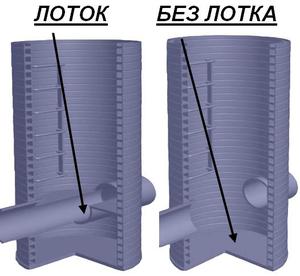
Elevation wells of the main
 The slopes of the route up to 3 m high are designed in the form of weirs from the working profile. If drops are provided up to 6 m high, then the connection is made in the form of a riser or walls for spreading a vertical arrangement. In this case, the specific flow rate of wastewater is determined at the rate of 0.3 m per second per linear meter of the width of the wall or the circumference of the section of the riser.
The riser is equipped with a receiving funnel on top and a metal plate at the base with a water pit below. Pits in risers with diameters less than 30 cm are not arranged; instead, a guide elbow is provided. Lines with a pipe diameter of up to 60 cm are equipped with a drain in the inspection chamber instead of installing a viewing well.
In the receiving collectors of rain sewers with a height difference of up to 100 cm, drop chambers are equipped according to the type of drain, a height difference of up to 300 cm requires a water pit with the installation of one grid made of slabs or beams, two grids are installed with a drain height difference of up to 400 cm.
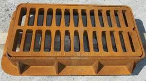
rainwater inlets
The construction of water intake chambers includes:
Storm water inlets are of a horizontal type, when gratings are installed on the surface of the street in the plane of the roadway. Vertical storm water inlets are practiced, the gratings of which are inserted into the side of the curb. Sometimes it is advisable to build mixed-type storm water inlets with vertical and horizontal gratings installed. They are not placed on the gentle slopes of the street terrain.
With a jagged, gently sloping street, the distance between the rainwater receivers is determined by calculation, taking into account the distance of the longitudinal slope and the depth of the liquid in the tray at the grate. Depth should not exceed 12 cm on a street with a straight gentle slope, the distance between atmospheric precipitation receivers is calculated from the condition that the width of the current in the flume should not exceed 2 m before entering the grate. For the calculation, the amount of precipitation of standard intensity for this area is taken.
![]() The data for calculating the distance from one storm water inlet to another are placed in special tables that take into account the conditions of the relief and the intensity of rainwater runoff. The length of the intermediate section from the manhole to the installed storm water inlet should not exceed 40 cm, on which it is allowed to install no more than one receiver. The diameter of the connecting pipe is determined from the intensity of the water flow to the grate at a slope of 0.02, but not more than 20 cm.
The data for calculating the distance from one storm water inlet to another are placed in special tables that take into account the conditions of the relief and the intensity of rainwater runoff. The length of the intermediate section from the manhole to the installed storm water inlet should not exceed 40 cm, on which it is allowed to install no more than one receiver. The diameter of the connecting pipe is determined from the intensity of the water flow to the grate at a slope of 0.02, but not more than 20 cm.
It is allowed to connect organized drains from the roof of buildings and drainage sewers to the installed storm water inlet. If the open tray should be brought to the closed highway, then this is done with the installation of settling wells. The grate in the head of the pit is made with gaps no larger than 5 cm, the diameter of the connecting pipes of the main is taken according to the calculation, but not less than 25 cm.
Road crossing device
For the intersection of automobile routes of the first and second categories and railway lines of the first, second and third values, pipelines are equipped with protective cases. Other categories of roads and rail links allow the laying of the water supply and sewerage line without a shell device. The intersection of pipelines with paths (under them) of pressure action must be laid from steel pipes. Non-pressure mains are allowed to be arranged with cast-iron elements.
A puncture under the roads must be coordinated with the city or regional special services in accordance with the established procedure. At the same time, the possibility of designing and laying additional roads and railways in this area is taken into account. All work on the arrangement of the intersection with artificial barriers is carried out in accordance with the provisions of SNiP 31.13330.
 To start carrying out measures to equip the crossing point, it is necessary to provide for the occurrence on the site under the road. Drainage is provided to the sewer. If there is no sewer line in the immediate vicinity, measures are being taken to prevent the confluence of wastewater with natural water bodies into the surrounding relief area. To do this, they arrange the switching of pipeline fittings, install additional collecting tanks and provide for an emergency shutdown of the pumps.
Preservation of the slope in the case is carried out by concreting platforms of a given height with the installation of retaining guide structures. On the upper surface of the case, it is allowed to lay electrical cables and communication wires in the design of pipes. In some cases, it is allowed, after laying the pipes, to fill the space between them and the walls of the case with cement mortar.
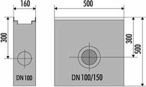 For cases that are laid by the installation method, the wall thickness is calculated depending on the degree of penetration, and thickness of the walls of the shell, which is laid by the puncture method or extrusion, is determined by the calculation, taking into account the amount of pressure of the jack, in order to avoid shape change and deformation.
Steel cases are necessarily treated inside and out with an anti-corrosion coating and insulation from moisture.
Pipe ventilation device
Household sewage is ventilated through the internal risers of the house sewer, but sometimes a device is provided forced ventilation sewer networks. Ventilation suit:
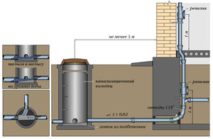
If the release of wastewater is envisaged in the area of sanitary or protected zones, residential areas and in places of accumulation of human flow, then they arrange treatment facilities for the neutralization and partial treatment of sewage.
Natural ventilation of external networks that drain wastewater with volatile poisonous and explosive components present in them is installed at each outlet from the house in the form of risers with a diameter of at least 20 cm. They should be placed in the heated area of the house, providing for them a connection with the hydraulic seal chamber. The outlet of the ventilation pipe is carried out above the roof of a residential building to a height of at least 70 cm.
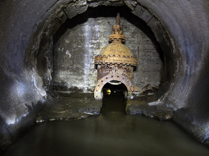 As for the ventilation of general sewer collectors and large-diameter channels, arranged by the shield or mining method, the design of the ventilation units is built according to special calculations, the drawings of which are given in the working draft.
The device of any type of pressure or non-pressure type of water supply and sewage lines requires a serious attitude. All work carried out construction organizations, are carried out in strict accordance with the provisions and standards prescribed in SNiP. This is the only way to avoid unpleasant moments associated with the pollution of drinking water and the deterioration of the ecology of the surrounding space.