Pipeline testing. All pressure pipelines after installation of the water pipeline are tested for strength and density by hydraulic and pneumatic methods.
The test of pressure pipelines laid in trenches is carried out twice: before backfilling the trenches and installing fittings (hydrants, safety valves, plungers) - a preliminary strength test and after backfilling the trenches and completing all work on this section of water pipes, but before installing hydrants, safety valves and plungers, instead of which plugs are installed for the duration of the test - the final density test.
It is allowed to conduct a preliminary test of the pipeline only after it has been fixed by tamping the sinuses with soil, powdering polyethylene pipes of the water supply system, installing stops, as well as other measures provided for by safety regulations. Preliminary testing of steel pipelines is carried out with positive results of quality control of welding and insulation.
welded joints and flange connections at a test pressure of less than 0.6 MPa, they must be without insulation at a distance of at least 100 mm from the axis of the joint in each direction and accessible for inspection.
Hydraulic strength test. The strength of pressure pipelines is checked by internal pressure. The working and test pressure of pressure pipelines is established by the project.
When conducting a preliminary hydraulic test of water pipes, the valves installed on this water pipe must be fully open. To disconnect the tested section of the water supply from the existing one, blind flanges or plugs are installed; the use of valves for this purpose is not permitted.
Pipelines made of cast iron and reinforced concrete pipes tested in sections no longer than 1 km, and pipelines made of polyethylene pipes no more than 0.5 km. test length sections of steel pipelines with the hydraulic test method, it is allowed to take more than 1 km.
Preliminary hydraulic testing of metal and reinforced concrete pipelines should last at least 10 minutes, and polyethylene - at least 30 minutes, after which the pressure is reduced to the working one and the pipelines are inspected. Maintaining the test, as well as working pressure in the pipeline for the period of its inspection and detection of defects during the preliminary test is allowed to be carried out by pumping water.
The pressure pipeline is considered to have passed the preliminary hydraulic test if, under test pressure, pipes and fittings did not break and sealing of butt joints was not violated, and no water leaks were detected under operating pressure.
The observed defects must be eliminated, after which the pipeline must be subjected to a preliminary test again.
Hydraulic tightness test. The final hydraulic test of pressure pipelines can be started if at least 24 hours have passed from the moment the trench was filled with soil and the pipeline was filled with water for metal and polyethylene pipes, and at least 72 hours for reinforced concrete pipes. If the pipeline was filled with water before the trenches were filled with soil, then the test pressure holding time is set from the moment of backfilling.
During the final test of pressure water supply pipelines, the actual leakage of water from the pipelines must be determined, while leakages must not exceed acceptable limits.
A section of a water supply system made of polyethylene pipes is considered to have passed the hydraulic test if, after successively holding the water supply under test and working pressure for 30 minutes, over the next 10 minutes of being under working pressure, the pressure drop in the water supply system did not exceed 0.01 MPa.
In a pipeline section that is fully accessible for inspection in working condition, a leak is not specifically determined, and it is considered to have passed the hydraulic test if its integrity is not violated at the test pressure, and no water leaks are detected in the pipeline at operating pressure.
Water leaks from the pipeline are determined by the formula, l / min:
q = Q/BT,
where T is the time from the start of the leak test until the pressure gauge needle returns to its original position (min) T=T1-T2; B - coefficient taken equal to 1 with a pressure drop of not more than 20% of the test pressure.
If within 10 minutes the pressure will drop below the working one, then the pipeline is considered to have failed the test and the volume of water Q required to restore pressure in it is not determined. If, after this time, the pressure drop is insufficient, then it should be increased to the required one by dumping water from the pipeline. Leaks are then calculated using the above formula. Water from the pipeline may be discharged before the expiration of the above period, but the discharge of water may be greater than the actual leakage.
If, when testing a pipeline made of reinforced concrete pipes, the actual leakage is greater than the permissible one, it is allowed to re-test the pipeline (without preliminary holding it). If, during the retest, the actual leakage does not exceed the allowable by more than 20%, the pipeline can be recognized as serviceable (with a guarantee that the builders will correct all defects within a year).
If, during the retest, the actual leakage exceeds the allowable by more than 20%, then it is recommended to keep the pipeline for 10 days under operating pressure in order to additionally saturate the pipe walls with water. After that, the pipeline test must be carried out again.
When filling the pipeline with water in winter conditions, the temperature difference between the pipe and water is allowed no more than 10 °C. The final hydraulic test of the pipeline in winter conditions should be carried out at a water temperature of at least 1°C.
The intended keeping of the pipeline with water without pressure must be carried out in the presence of a flow, that is, water must be pumped through the pipeline to warm it up. Testing of pipelines in winter can be allowed only if it is absolutely necessary to put them into operation during the current winter period.
All installed pipelines must be subjected to hydraulic tests. At a test pressure not exceeding 0.8 MPa, a pneumatic test method is allowed.
Testing of pipelines should be carried out in accordance with the requirements of SNiP "Rules for the production and acceptance of work. Water supply, sewerage and heat supply. External networks and structures”.
The test pressure is set by the project. In the absence of special instructions in the project, the hydraulic test pressure during preliminary and final tests should be equal to the working pressure plus 0.3 MPa.
The ends of the pipeline section before the hydraulic test must be hermetically sealed with plugs, the butt joints of which are recommended to be the same as on the main pipeline, that is, using rubber sealing rings. For plugs, steel connecting pipes can be used, designed for mounting fittings and fittings. When steel pipes are used as plugs, a blank flange with stainless steel pipes must be welded to the free end of the pipe. gas pipes for filling the pipeline with water and venting air.
To hold the end caps, it is advisable to use stops of a metal structure with hydraulic cylinders. The drive of these cylinders can be carried out from any tractor equipped with hydraulic system. The design of such an emphasis can be used repeatedly.
In the absence of stops of a metal structure, a concrete or reinforced stop can be used, which should have design strength by the time the pipeline is filled with water, therefore it is recommended to install such stops simultaneously with the laying of the pipeline. The design of temporary end stops must be provided for in the pipeline design.
By the time of the hydraulic test of the pipeline, all butt joints, both inside and outside, must be sealed with a cement-sand mortar, which must be aged for at least 2 days before testing the pipeline.
Gate valves installed on the pipeline must be fully open during testing. Gate valves that disconnect the pipeline from branches can be either open or closed for the test period, but in all cases, dry flanges must be installed after them. It is not allowed to use valves to disconnect the tested section of the pipeline from the existing networks.
The pipeline is filled with water from a lower section in order to ensure best conditions to remove air from the pipeline. The valves on the pipes through which air is vented should be closed only after complete venting.
The pipeline is considered to have passed the test if there is no decompression of butt joints and violation of the integrity of pipes, fittings and fittings, no unacceptable defects are found both in open places and in places where the sinuses of the trenches are covered with soil.
The pipeline is considered to have passed the final hydraulic test if there is no water leakage from the pipeline.
Pneumatic test are used at the discretion of the building organization in case of difficulties during the hydraulic test (winter time, lack of water at the test site, etc.). These tests are also carried out in two stages: preliminary - for strength, final - for density.
After filling the steel pipeline with air before testing, the external pipelines must be held for some time to equalize the air temperature in the pipeline with the ground temperature. The minimum holding time with a nominal diameter of the pipeline Dy=300 mm is 2 hours, Dy=600 mm -4 hours, Dy=900 mm -8 hours; Dy=1200 mm - 16 h and Dy=1400 mm -24 h.
The minimum holding time for reinforced concrete prestressed pipelines with a nominal diameter of the pipeline Dy=300 mm is 6 hours; Dy = 300-500 mm-12 h; Dy more than 500 mm -24 h.
Preliminary pneumatic testing of pipelines after their partial backfilling is carried out as follows:
- steel and polyethylene pipelines at operating pressure up to 0.5 MPa - test pressure 0.6 MPa;
- at a working pressure over 0.5 MPa - a test pressure equal to the working one, with a coefficient of 1.15;
- cast iron, reinforced concrete prestressed pipelines - with a test pressure of 0.15 MPa.
If it is impossible to create the test pressure specified for steel and polyethylene pipelines, the preliminary test may be carried out at the maximum pressure developed by the compressor, but not less than 0.6 MPa.
Pneumatic testing of pipelines should be carried out in sections no longer than 1 km. Defects are eliminated after the pressure in the pipeline is reduced to atmospheric, then the test is repeated.
In preparation for the pneumatic test, check the setting of the stops; sprinkle the pipeline with soil above the shelygi by at least 25 cm; clean the inner surface of the pipeline from soil, scale and remove other blockages by blowing or in another way; fix the protection zone with warning signs (red flags) during pneumatic testing of pipelines.
When testing pipelines laid on the streets, the boundaries of the zone are established taking into account local conditions and the adoption of additional protection measures.
It is allowed to inspect pipelines and mark defective places only after the pressure in the pipeline is reduced to 0.1 MPa, and defects should be eliminated at atmospheric pressure.
Pressing equipment. To test pipelines, industry produces pressure testing units and pumps.
7.1. If there is no indication in the project about the method of testing, pressure pipelines are subject to strength and tightness testing, as a rule, by hydraulic method. Depending on the climatic conditions in the construction area and in the absence of water, a pneumatic test method can be used for pipelines with an internal design pressure Рр, not more than:
underground cast iron, asbestos cement and reinforced concrete - 0.5 MPa (5 kgf / cm2);
underground steel - 1.6 MPa (16 kgf / cm2);
elevated steel - 0.3 MPa (3 kgf / cm2).
7.2. Testing of pressure pipelines of all classes should be carried out by a construction and installation organization, as a rule, in two stages:
the first is a preliminary test for strength and tightness, performed after backfilling the sinuses with soil tamping to half the vertical diameter and powdering pipes in accordance with the requirements of SNiP 3.02.01-87 with butt joints left open for inspection; this test can be performed without the participation of representatives of the customer and the operating organization with the drawing up of an act approved by the chief engineer of the construction organization;
the second - the acceptance (final) test for strength and tightness should be performed after the pipeline is completely backfilled with the participation of representatives of the customer and the operating organization with the preparation of an act on the test results in the form of mandatory annexes 1 or 3.
Both stages of the test must be carried out before the installation of hydrants, air vents, safety valves, instead of which flange plugs should be installed during the test. Preliminary testing of pipelines accessible for inspection in working condition or subject to immediate backfilling during the construction process (work in winter, in cramped conditions), with appropriate justification in the projects, may not be carried out.
7.3. Pipelines of underwater crossings are subject to preliminary testing twice: on a slipway or site after welding of pipes, but before applying anti-corrosion insulation to welded joints, and again - after laying the pipeline in a trench in the design position, but before backfilling with soil.
The results of preliminary and acceptance tests should be drawn up in an act in the form of mandatory Appendix 1.
7.4. Pipelines laid at crossings over railways and highways of categories I and II are subject to preliminary testing after laying the working pipeline in a case (casing) until the annular space of the case cavity is filled and before the working and receiving pits of the crossing are backfilled.
7.5. The values of the internal design pressure РР and test pressure Ри for carrying out preliminary and acceptance tests of the pressure pipeline for strength must be determined by the project in accordance with the requirements of SNiP 2.04.02-84 and indicated in the working documentation.
The value of the test pressure for tightness Рg for both preliminary and acceptance tests of the pressure pipeline must be equal to the value of the internal design pressure Рр plus the value Р, taken in accordance with Table. 4 depending on the upper limit of pressure measurement, accuracy class and division value of the pressure gauge scale. In this case, the value of Рg should not exceed the value of the acceptance test pressure of the pipeline for strength Pu.
7.6* Pipelines made of steel, cast iron, reinforced concrete and asbestos-cement pipes, regardless of the test method, should be tested at a length of less than 1 km - at one time; with a greater length - in sections of no more than 1 km. The length of the test sections of these pipelines with the hydraulic test method is allowed to be taken over 1 km, provided that the value of the allowable flow rate of pumped water should be determined as for a section 1 km long.
Pipelines made of LDPE, HDPE and PVC pipes, regardless of the test method, should be tested with a length of no more than 0.5 km at a time, with a longer length - in sections of no more than 0.5 km. With appropriate justification in the project, it is allowed to test these pipelines at one time with a length of up to 1 km, provided that the value of the allowable flow rate of pumped water should be determined as for a section with a length of 0.5 km.
Table 4
|
The value of the internal design pressure in the pipeline P p, MPa (kgf / cm 2) |
P for various values of the internal design pressure P p in the pipeline and the characteristics of the technical pressure gauges used |
|||||||||||||||||
|
division price, MPa (kgf / cm 2) |
R, MPa (kgf / cm 2) |
upper limit of pressure measurement, MPa (kgf / cm 2) |
division price, MPa (kgf / cm 2) |
R, MPa (kgf / cm 2) |
upper limit of pressure measurement, MPa (kgf / cm 2) |
division price, MPa (kgf / cm 2) |
R, MPa (kgf / cm 2) |
upper limit of pressure measurement, MPa (kgf / cm 2) |
division price, MPa (kgf / cm 2) |
R, MPa (kgf / cm 2) |
||||||||
|
Accuracy classes of technical pressure gauges |
||||||||||||||||||
|
Up to 0.4 (4) |
0,002 (0,02) |
0,02 (0,2) |
0,6(6) |
0,005 (0,05) |
0,03 (0,3) |
0,005 (0,05) |
0,05 (0,5) |
0,01 (0,1) |
0,07 (0,7) |
|||||||||
|
0.41 to 0.75 (from 4.1 to 7.5) |
(10) |
0,005 (0,05) |
0,04 (0,4) |
(16) |
0,01 (0,1) |
0,07 (0,7) |
(16) |
0,01 (0,1) |
(16) |
0,02 (0,2) |
0,14 (1,4) |
|||||||
|
0.76 to 1.2 (from 7.6 to 12) |
(16) |
0,005 (0,05) |
0,05 (0,5) |
(16) |
0,01 (0,1) |
0,09 (0,9) |
(25) |
0,02 (0,2) |
0,14 (1,4) |
(25) |
0,05 (0,5) |
0,25 (2,5) |
||||||
|
1.21 to 2.0 (from 12.1 to 20) |
(25) |
0,01 (0,1) |
(25) |
0,02 (0,2) |
0,14 (1,4) |
(40) |
0,05 (0,5) |
0,25 2,5) |
(40) |
|||||||||
|
2.01 to 2.5 (from 20.1 to 25) |
(40) |
0,02 (0,2) |
0,14 (1,4) |
(40) |
0,05 (0,5) |
0,25 (2,5) |
(40) |
0,05 (0,5) |
(60) |
|||||||||
|
2.51 to 3.0 (from 25.1 to 30) |
(40) |
0,02 (0,2) |
0,16 (1,6) |
(40) |
0,05 (0,5) |
0,25 (2,5) |
(60) |
0,05 (0,5) |
0,35 (3,5) |
(60) |
||||||||
|
3.01 to 4.0 (from 30.1 to 40) |
(60) |
0,02 (0,2) |
(60) |
0,05 (0,5) |
(60) |
0,05 (0,5) |
0,45 (4,5) |
(60) |
||||||||||
|
4.01 to 5.0 (from 40.1 to 50) |
(60) |
(0,2) |
0,24 (2,4) |
(60) |
0,05 (0,5) |
(100) |
(100) |
(10) |
||||||||||
7.7. If there are no indications in the project on the value of the hydraulic test pressure Pi to perform a preliminary test of pressure pipelines for strength, the value is taken in accordance with Table. 5*
Table 5
|
Pipeline characteristics |
The value of the test pressure during the preliminary test, MPa (kgf / cm 2) |
||
|
1. Steel I class* with butt joints for welding (including underwater) with an internal design pressure P p up to 0.75 MPa (7.5 kgf / cm 2) |
1,5 (15) |
||
|
2. The same, from 0.75 to 2.5 MPa (from 7.5 to 25 kgf / cm 2) |
Internal design pressure with a factor of 2, but not more than the factory test pressure of the pipes |
||
|
3. The same, St. 2.5 MPa (25 kgf / cm 2) |
Internal calculation pressure with a factor of 1.5, but not more than the factory test pressure of the pipes |
||
|
4. Steel, consisting of flanged sections with internal design pressure m R p up to 0.5 MPa (5 kgf / cm 2) |
0,6 (6) |
||
|
5. Steel of the 2nd and 3rd classes with butt joints welding pressure and internal design pressure R p up to 0.75 MPa (7.5 kgf / cm 2) |
1,0 (10) |
||
|
6. The same, from 0.75 to 2.5 MPa (from 7.5 to 25 kgf / cm 2) |
Internal design pressure with a factor of 1.5, but not more than the factory test pressure of the pipes |
||
|
7. The same, St. 2.5 MPa (25 kgf / cm 2) |
Internal calculation pressure with a factor of 1.25, but not more than the factory test pressure of the pipes |
||
|
8. Gravity steel water intake or sewer outlet |
Installed by a projector |
||
|
9. Cast iron with butt joints for caulking (according to GOST 9583-75 for pipes of all classes) with an internal design pressure of up to 1 MPa (10 kgf / cm 2) |
Internal design pressure plus 0.5 (5) but not less than 1 (10) and not more than 1.5 (15) |
||
|
10. The same, with butt joints on rubber cuffs for pipes of all classes |
Internal morning design pressure with a coefficient of 1.5, but not less than 1.5 (15) and not more than 0.6 of the factory test hydraulic pressure |
||
|
11. Reinforced concrete |
Internal design pressure with a factor of 1.3, but not more than the factory test pressure for watertightness |
||
|
12. Asbestos cement |
Internal design pressure with a coefficient of 1.3, but not more than 0.6 of the factory test pressure for watertightness |
||
|
13. Plastic |
Internal design pressure with a factor of 1.3 |
||
Piping classes are accepted according to SNiP 2.04.02-84.
7.8. Prior to the preliminary and acceptance tests of pressure pipelines, the following must be done:
all work on sealing butt joints, installation of stops, installation of connecting parts and fittings was completed, satisfactory results were obtained for quality control of welding and insulation of steel pipelines;
flange plugs were installed on the outlets instead of hydrants, air vents, safety valves and at the points of connection to the pipelines in operation;
means of filling, pressure testing and emptying the test area were prepared, temporary communications were installed and devices and valves necessary for testing were installed;
wells were drained and ventilated for preparatory work, duty was organized at the border of the plots security zone;
the tested section of the pipeline is filled with water (during the hydraulic test method) and air is removed from it.
The procedure for hydraulic testing of pressure pipelines for strength and tightness is set out in the recommended Appendix 2.
7.9. In order to test the pipeline, the responsible work contractor must be issued a work permit for the performance of high-risk work, indicating in it the size of the buffer zone. The form of the work permit and the procedure for issuing it must comply with the requirements of SNiP III-4-80*.
7.10. To measure hydraulic pressure during preliminary and acceptance testing of pipelines for strength and tightness, duly certified spring pressure gauges with an accuracy class of at least 1.5 with a body diameter of at least 160 mm and with a scale for nominal pressure of about 4/3 of the test pressure should be used.
To measure the volume of water pumped into and out of the pipeline during the test, measuring tanks or meters should be used. cold water(water meters) in accordance with GOST 6019-83, certified in the prescribed manner.
7.11. The filling of the tested pipeline with water should be carried out, as a rule, with an intensity, m3 / h, not more than: 4 - 5 - for pipelines with a diameter of up to 400 mm; 6 - 10 - for pipelines with a diameter of 400 to 600 mm; 10 - 15 - for pipelines with a diameter of 700 - 1000 mm and 15 - 20 - for pipelines with a diameter of more than 1100 mm.
When filling the pipeline with water, air must be removed through open taps and valves.
7.12. It is allowed to start the acceptance hydraulic test of the pressure pipeline after filling it with soil in accordance with the requirements of SNiP 3.02.01-87 and filling it with water for the purpose of water saturation, and if at the same time it was kept in the filled state for at least: 72 hours - for reinforced concrete pipes (including including 12 hours under internal design pressure Рр); asbestos-cement pipes - 24 hours (including 12 hours under internal design pressure Рр); 24 hours - for cast iron pipes. For steel and polyethylene pipelines, holding for the purpose of water saturation is not performed.
If the pipeline was filled with water before backfilling with soil, then the indicated duration of water saturation is set from the moment the pipeline is backfilled.
7.13. The pressure pipeline is recognized as having passed the preliminary and acceptance hydraulic tests for tightness, if the flow rate of pumped water does not exceed the allowable flow rate of pumped water for a test section 1 km long or more specified in Table. 6*.
If the flow rate of the pumped water exceeds the allowable one, then the pipeline is recognized as having failed the test and measures must be taken to detect and eliminate hidden defects in the pipeline, after which the pipeline must be retested.
Table 6
|
Internal diameter of the pipeline, mm |
Permissible flow rate of pumped water to a tested section of a pipeline 1 km long or more, l/min, at acceptance test pressure for pipes |
|||
|
steel |
cast iron |
asbestos-cement |
reinforced concrete |
|
|
0,28 |
0,70 |
1,40 |
||
|
0,35 |
0,90 |
1,56 |
||
|
0,42 |
1,05 |
1,72 |
||
|
0,56 |
1,40 |
1,98 |
||
|
0,70 |
1,55 |
2,22 |
||
|
0,85 |
1,70 |
2,42 |
||
|
0,90 |
1,80 |
2,62 |
||
|
1,00 |
1,95 |
2,80 |
||
|
1,05 |
2,10 |
2,96 |
||
|
1,10 |
2,20 |
3,14 |
||
|
1,20 |
2,40 |
|||
|
1,30 |
2,55 |
|||
|
1,35 |
2,70 |
|||
|
1,45 |
2,90 |
|||
|
1000 |
1,50 |
3,00 |
||
|
1100 |
1,55 |
|||
|
1200 |
1,65 |
|||
|
1400 |
1,75 |
|||
|
1600 |
1,85 |
|||
|
1800 |
1,95 |
|||
|
2000 |
2,10 |
|||
Notes: 1. For cast iron pipelines with butt joints on rubber seals the allowable flow rate of pumped water should be taken with a factor of 0.7.
2. If the length of the tested section of the pipeline is less than 1 km, the allowable flow rates of pumped water given in the table should be multiplied by its length, expressed in km; with a length of more than 1 km, the allowable flow of pumped water should be taken as for 1 km.
3. For LDPE and HDPE pipelines with welded joints and PVC pipelines with adhesive joints, the allowable flow rate of pumped water should be taken as for steel pipelines equivalent in outer diameter, determining this flow rate by interpolation.
4. For PVC pipelines with rubber cuff connections, the allowable flow rate of pumped water should be taken as for cast iron pipelines with the same connections, equivalent in outer diameter, determining this flow rate by interpolation.
7.14. The value of the test pressure when testing pipelines pneumatically for strength and tightness in the absence of data in the project should be taken:
for steel pipelines with design internal pressure Рр up to 0.5 MPa (5 kgf/cm2) incl. - 0.6 MPa (6 kgf/cm2) during preliminary and acceptance testing of pipelines;
for steel pipelines with a design internal pressure of Pp 0.5 - 1.6 MPa (5 - 16 kgf / cm2) - 1.15 Pp during preliminary and acceptance tests of pipelines;
for cast iron, reinforced concrete and asbestos-cement pipelines, regardless of the design internal pressure - 0.15 MPa (1.5 kgf / cm2) - during preliminary and 0.6 MPa (6 kgf / cm2) - acceptance tests.
7.15. After filling the steel pipeline with air, before testing it, the air temperature in the pipeline and the soil temperature should be equalized. Minimum exposure time depending on the diameter of the pipeline, h, at Dy:
Up to 300 mm - 2
From 300 to 600 "- 4
« 600 « 900 « - 8
« 900 « 1200 « - 16
« 1200 «1400 « - 24
St. 1400 "- 32
7.16. When conducting a preliminary pneumatic strength test, the pipeline should be kept under test pressure for 30 minutes. Air must be pumped in to maintain the test pressure.
7.17. Inspection of the pipeline in order to identify defective places is allowed to be carried out with a decrease in pressure: in steel pipelines - up to 0.3 MPa (3 kgf / cm2); in cast iron, reinforced concrete and asbestos-cement - up to 0.1 MPa (1 kgf / cm2). In this case, the detection of leaks and other defects in the pipeline should be carried out by the sound of leaking air and by the bubbles that form at the places of air leaks through butt joints coated on the outside with a soapy emulsion.
7.18. Defects identified and noted during the inspection of the pipeline should be eliminated after reducing the excess pressure in the pipeline to zero. After the defects are eliminated, the pipeline must be retested.
7.19. The pipeline is recognized as having passed the preliminary pneumatic strength test if a thorough inspection of the pipeline does not reveal a violation of the integrity of the pipeline, defects in the joints and welded joints.
7.20. The pneumatic acceptance test of pipelines for strength and tightness must be carried out in the following sequence:
the pressure in the pipeline should be brought to the value of the test pressure for strength specified in clause 7.14, and the pipeline should be kept under this pressure for 30 minutes; if there is no violation of the integrity of the pipeline under the test pressure, then the pressure in the pipeline is reduced to 0.05 MPa (0.5 kgf / cm2) and the pipeline is kept under this pressure for 24 hours;
after the expiration of the holding period of the pipeline under a pressure of 0.05 MPa (0.5 kgf / cm2), a pressure equal to 0.03 MPa (0.3 kgf / cm2) is set, which is the initial test pressure of the pipeline for tightness Рn, the start time of the test for tightness, as well as barometric pressure RBn, mm Hg. Art., corresponding to the start of the test;
test the pipeline under this pressure for the time specified in Table. 7;
after the time specified in the table. 7, measure the final pressure in the pipeline Pk, mm w.c. Art., and the final barometric pressure Rbk, mm Hg;
the magnitude of the pressure drop P, mm of water. Art., determined by the formula
P \u003d (P n - P k) + 13.6 (P b n - P b k).
Table 7
|
Internal diameter of pipes, mm |
Pipelines |
|||||
|
steel |
cast iron |
asbestos cement and reinforced concrete |
||||
|
test duration, h - min |
allowable pressure drop during the test, mm of water. Art. |
test duration, h-min |
allowable pressure drop during the test, mm of water. Art. |
|||
|
0-30 |
0-15 |
0-15 |
||||
|
125 |
0-30 |
0-15 |
0-15 |
|||
|
1-00 |
0-15 |
0-15 |
||||
|
1-00 |
0-30 |
0-30 |
||||
|
25 0 |
1-00 |
0-30 |
0-30 |
|||
|
2-00 |
1-00 |
1-00 |
||||
|
2-00 |
1-00 |
1-00 |
||||
|
2-00 |
1-00 |
2-00 |
||||
|
4-00 |
2-00 |
3-00 |
||||
|
4-00 |
2-00 |
3-00 |
||||
|
4-00 |
2-00 |
3-00 |
||||
|
6-00 |
3-00 |
5-00 |
||||
|
6-00 |
3-00 |
5-00 |
||||
|
6-00 |
4-00 |
6-00 |
||||
|
1000 |
12-00 |
4-00 |
6-00 |
|||
|
1200 |
12-00 |
|||||
|
1400 |
12-00 |
|||||
When used in a pressure gauge as a working fluid, water \u003d 1, kerosene - = 0,87.
Note. By agreement with the design organization, the duration of pressure reduction can be reduced by half, but not less than 1 hour; in this case, the value of the pressure drop should be taken in a proportionally reduced size.
7.21. The pipeline is recognized as having passed the acceptance (final) pneumatic test if its integrity is not violated and the value of the pressure drop P, determined by formula (1), does not exceed the values \u200b\u200bspecified in Table 7. In this case, the formation of air bubbles on the outer wetted surface of reinforced concrete pressure pipes is allowed.
7.22. A non-pressure pipeline should be tested for tightness twice: preliminary - before backfilling and acceptance (final) after backfilling in one of the following ways:
the first is to determine the volume of water added to the pipeline laid in dry soils, as well as in wet soils, when the level (horizon) of groundwater at the upper well is located below the earth's surface by more than half the depth of the pipes, counting from the hatch to the shelyga;
the second is to determine the inflow of water into a pipeline laid in wet soils, when the level (horizon) of groundwater at the upper well is located below the earth's surface by less than half the depth of the pipes, counting from the hatch to the shelyga. The pipeline testing method is established by the project.
7.23. Wells of non-pressure pipelines with waterproofing with inside, should be tested for tightness by determining the volume of added water, and wells with waterproofing from the outside - by determining the inflow of water into them.
Wells that have waterproof walls, internal and external insulation according to the project, can be tested for the addition of water or inflow ground water, in accordance with paragraph 7.22, together with pipelines or separately from them.
Wells that do not have waterproof walls, internal or external waterproofing according to the project, are not subjected to an acceptance test for tightness.
7.24. Leak testing of non-pressure pipelines should be carried out between adjacent wells.
In case of difficulties with the delivery of water, justified in the project, it is allowed to test non-pressure pipelines selectively (as directed by the customer): with a total length of the pipeline up to 5 km - two or three sections; with a pipeline length of more than 5 km - several sections with a total length of at least 30%.
If the results of selective testing of pipeline sections are unsatisfactory, then all sections of the pipeline are subject to testing.
7.25. Hydrostatic pressure in the pipeline during its preliminary test must be created by filling the riser installed at its upper point with water, or by filling the upper well with water, if the latter is to be tested. In this case, the value of the hydrostatic pressure at the top of the pipeline is determined by the magnitude of the excess of the water level in the riser or well above the pipeline rack or above the groundwater horizon, if the latter is located above the rack. The value of the hydrostatic pressure in the pipeline during its testing must be indicated in the working documentation. For pipelines laid from non-pressure concrete, reinforced concrete and ceramic pipes, this value, as a rule, should be equal to 0.04 MPa (0.4 kgf / cm2).
7.26. Preliminary testing of pipelines for tightness is carried out with the pipeline not sprinkled with earth for 30 minutes. The value of the test pressure must be maintained by adding water to the riser or to the well, preventing the water level in them from dropping by more than 20 cm.
The pipeline and the well are recognized as having passed the preliminary test if no water leaks are found during their inspection. If there are no increased requirements for the tightness of the pipeline on the surface of pipes and joints in the project, sweating is allowed with the formation of drops that do not merge into one stream with the amount of sweating not more than 5% of the pipes in the test section.
7.27. The acceptance test for tightness should begin after soaking in the water-filled state of the reinforced concrete pipeline and wells with waterproofing on the inside or watertight walls according to the design - for 72 hours and pipelines and wells from other materials - 24 hours.
7.28. The tightness during the acceptance test of the backfilled pipeline is determined by the following methods:
the first - according to the volume measured in the upper well, added to the riser or well of water for 30 minutes; while lowering the water level in the riser or in the well is allowed no more than 20 cm;
the second - according to the volume of groundwater flowing into the pipeline measured in the lower well.
The pipeline is recognized as having passed the acceptance test for tightness, if the volumes of added water determined during the test according to the first method (groundwater inflow according to the second method) will not exceed those indicated in Table. 8*, about which an act must be drawn up in the form of a mandatory annex 4.
Table 8
|
Nominal pipeline diameter D y, mm |
Permissible volume of water added to the pipeline (water inflow) per 10 m of the length of the tested pipeline during the test of 30 minutes, l, for pipes |
||
|
reinforced concrete and concrete |
ceramic |
asbestos-cement |
|
|
4,2 |
|||
Notes: 1. If the duration of the test is increased by more than 30 minutes, the value of the allowable volume of added water (water inflow) should be increased in proportion to the increase in the duration of the test.
2. The value of the allowable volume of added water (water inflow) into a reinforced concrete pipeline with a diameter of more than 600 mm should be determined by the formula
q = 0.83 (D + 4), l, per 10 m of pipeline length during the test, 30 min, (2)
where D is the internal (conditional) diameter of the pipeline, dm.
3. For reinforced concrete pipelines with butt joints on rubber seals, the allowable volume of added water (water inflow) should be taken with a factor of 0.7.
4. The allowable volumes of added water (water inflow) through the walls and bottom of the well per 1 m of its depth should be taken equal to the allowable volume of added water (water inflow) per 1 m of pipe length, the diameter of which is equal in area to the inner diameter of the well.
5. The allowable volume of added water (water inflow) to a pipeline constructed from prefabricated reinforced concrete elements and blocks should be taken the same as for pipelines made of reinforced concrete pipes that are equal in cross-sectional area.
6. Permissible volume of water added to the pipeline (water inflow) per 10 m of the length of the tested pipeline during the test of 30 minutes for LDPE and HDPE pipes with welded joints and pressure pvc pipes with adhesive joints should be determined for diameters up to 500 mm inclusive. according to the formula q \u003d 0.03D, with a diameter of more than 500 mm - according to the formula q \u003d 0.2 + 0.03D, where D is the outer diameter of the pipeline, dm; q - the value of the allowable volume of added water, l.
7. The allowable volume of water added to the pipeline (water inflow) per 10 m of the length of the pipeline under test during the test period of 30 minutes for PVC pipes with rubber collar joints should be determined by the formula q \u003d 0.06 + 0.01D, where D is the outer diameter pipeline, dm; q - the value of the allowable volume of added water, l.
7.29. Rain sewer pipelines are subject to preliminary and acceptance testing for tightness in accordance with the requirements of this subsection, if provided for by the project.
7.30. Pipelines made of non-pressure reinforced concrete socket, seam and smooth-ended pipes with a diameter of more than 1600 mm, designed according to the project for pipelines that constantly or periodically operate under pressure up to 0.05 MPa (B m of water column) and have a special waterproof outer or inner lining are subject to a hydraulic pressure test specified in the project.
7.31. Hydraulic testing for water tightness (tightness) of capacitive structures must be carried out after the concrete reaches the design strength, they are cleaned and washed.
Waterproofing and soiling of capacitive structures should be carried out after obtaining satisfactory results of hydraulic testing of these structures, unless other requirements are justified by the project.
7.32. Before carrying out a hydraulic test, the capacitive structure should be filled with water in two stages:
the first - filling to a height of 1 m with exposure for a day;
the second - filling up to the design mark.
A capacitive structure filled with water to the design mark should be kept for at least three days.
7.33. A capacitive structure is recognized as having passed the hydraulic test if the loss of water in it per day does not exceed 3 liters per 1 m2 of the wetted surface of the walls and bottom, no signs of leakage are found in the seams and walls, and soil moisture in the base is not established. Only darkening and slight sweating of individual places is allowed.
When testing the watertightness of capacitive structures, the loss of water by evaporation from the open water surface should be taken into account additionally.
7.34. In the presence of jet leaks and water leaks on the walls or soil moisture at the base, the capacitive structure is considered to have failed the test, even if the water loss in it does not exceed the normative ones. In this case, after measuring the loss of water from the structure with a full flood, the places to be repaired should be fixed.
After elimination of the identified defects, a re-test of the capacitive structure should be carried out.
7.35. When testing tanks and containers for storing aggressive liquids, water leakage is not allowed. The test should be carried out before applying the anti-corrosion coating.
7.36. The pressure channels of filters and contact clarifiers (prefabricated and monolithic reinforced concrete) are subjected to hydraulic testing with the design pressure specified in the working documentation.
7.37. The pressure channels of filters and contact clarifiers are recognized as having passed the hydraulic test if, during visual inspection, no water leaks are found in the side walls of the filters and above the channel and if within 10 minutes the test pressure does not decrease by more than 0.002 MPa (0.02 kgf / cm2) .
7.38. The water-collecting reservoir of the cooling towers must be watertight and during the hydraulic test of this reservoir on the inner surface of its walls, darkening or slight sweating of individual places is not allowed.
7.39. Drinking water tanks, sedimentation tanks and other capacitive structures after the installation of floors are subject to a hydraulic test for water tightness in accordance with the requirements of paragraphs. 7.31-7.34.
The drinking water reservoir before the waterproofing device and backfilling with soil is subject to an additional test for vacuum and overpressure, respectively, with vacuum and overpressure air in the amount of 0.0008 MPa (80 mm of water column) for 30 minutes and is recognized as having passed the test if the values, respectively vacuum and gauge pressures will not decrease by more than 0.0002 MPa (20 mm of water column) in 30 minutes, unless other requirements are justified by the project.
7.40. The methane tank (cylindrical part) should be subjected to a hydraulic test in accordance with the requirements of paragraphs. 7.31-7.34, and the overlap, the metal gas cap (gas collector) should be tested for tightness (gas tightness) pneumatically at a pressure of 0.005 MPa (500 mm water column).
The methane tank is maintained under test pressure for at least 24 hours. If defective places are found, they must be eliminated, after which the structure must be tested for pressure drop for an additional 8 hours. The methane tank is recognized as having passed the tightness test if the pressure in it does not decrease in 8 hours more than 0.001 MPa (100 mm water column).
7.41. The caps of the drainage-distribution system of filters after their installation before loading the filters should be tested by supplying water with an intensity of 5-8 l / (s × m2) and air with an intensity of 20 l / (s × m2) three times with a frequency of 8-10 minutes. The defective caps found at the same time are subject to replacement.
7.42. Completed construction pipelines and facilities for domestic and drinking water supply before acceptance into operation are subject to washing (cleaning) and disinfection by chlorination, followed by washing until satisfactory control physical, chemical and bacteriological analyzes of water are obtained that meet the requirements of GOST 2874-82 and "Instructions for monitoring the disinfection of household - drinking water and for the disinfection of waterworks with chlorine for centralized and local water supply” of the USSR Ministry of Health.
7.43. Flushing and disinfection of pipelines and facilities for domestic and drinking water supply should be carried out by the construction and installation organization that performed the laying and installation of these pipelines and structures, with the participation of representatives of the customer and the operating organization under control carried out by representatives of the sanitary and epidemiological service. The procedure for flushing and disinfecting pipelines and utility water supply facilities is set out in the recommended Appendix 5.
7.44. An act must be drawn up on the results of the flushing and disinfection of pipelines and facilities for domestic and drinking water supply in the form given in the mandatory Appendix 6.
The test results of capacitive structures should be formalized in an act signed by representatives of the construction and installation organization, the customer and the operating organization.
7.45. Pressure pipelines for water supply and sewerage, constructed in conditions of subsiding soils of all types outside the territory of industrial sites and settlements, are tested in sections no longer than 500 m; on the territory of industrial sites and settlements, the length of the test sections should be assigned taking into account local conditions, but not more than 300 m.
7.46. Checking the water resistance of capacitive structures built on subsiding soils of all types should be carried out after 5 days after they are filled with water, while the loss of water per day should not exceed 2 liters per 1 m2 of the wetted surface of the walls and bottom.
If a leak is detected, water from the structures should be released and discharged to the places specified by the project, excluding flooding of the built-up area.
7.47. Hydraulic testing of pipelines and capacitive structures erected in areas of permafrost should be carried out, as a rule, at an ambient temperature of at least 0 ° C, unless other test conditions are justified by the project.
PRESSURE PIPING
7.1. If there is no indication in the project about the method of testing, pressure pipelines are subject to strength and tightness testing, as a rule, by hydraulic method. Depending on the climatic conditions in the construction area and in the absence of water, a pneumatic test method can be used for pipelines with an internal design pressure P p, not more than:
underground cast iron, asbestos cement and reinforced concrete - 0.5 MPa (5 kgf / cm 2);
underground steel - 1.6 MPa (16 kgf / cm 2);
elevated steel - 0.3 MPa (3 kgf / cm 2).
7.2. Testing of pressure pipelines of all classes should be carried out by a construction and installation organization, as a rule, in two stages:
first- preliminary test for strength and tightness, performed after filling the sinuses with soil tamping to half the vertical diameter and powdering pipes in accordance with the requirements SNiP 3.02.01-87 with butt joints left open for inspection; this test can be performed without the participation of representatives of the customer and the operating organization with the drawing up of an act approved by the chief engineer of the construction organization;
second- acceptance (final) testing for strength and tightness should be carried out after the pipeline is completely backfilled with the participation of representatives of the customer and the operating organization with the preparation of an act on the test results in the form of mandatory or.
Both stages of the test must be carried out before the installation of hydrants, air vents, safety valves, instead of which flange plugs should be installed during the test. preliminary pipeline testing, available for inspection in working order or subject to immediate backfilling during the construction process (work in winter, in cramped conditions), with appropriate justification in the projects, it is allowed not to produce.
7.3. Pipelines of underwater crossings are subject to preliminary testing twice: on a slipway or site after welding pipes, but before applying anti-corrosion insulation to welded joints, and again - after laying the pipeline in a trench in the design position, but before backfilling with soil.
The results of preliminary and acceptance tests must be drawn up in an act in the form of a mandatory one.
7.4. Pipelines laid at crossings over railways and highways of categories I and II are subject to preliminary testing after laying the working pipeline in a case (casing) until the annular space of the case cavity is filled and before the working and receiving pits of the crossing are backfilled.
7.5. The values of the internal design pressure Р Р and test pressure Р and for carrying out preliminary and acceptance tests of the pressure pipeline for strength must be determined by the project in accordance with the requirements SNiP 2.04.02-84 and specified in the working documentation.
The value of the test pressure for tightness Р g for both preliminary and acceptance tests of the pressure pipeline must be equal to the value of the internal design pressure Р р plus the value ∆Р, taken in accordance with tab. 4 depending on the upper limit of pressure measurement, accuracy class and division value of the pressure gauge scale. In this case, the value of Р g should not exceed the value of the acceptance test pressure of the pipeline for strength Р and.
7.6* Pipelines made of steel, cast iron, reinforced concrete and asbestos-cement pipes, regardless of the test method, should be tested at a length of less than 1 km - at one time; with a greater length - in sections of no more than 1 km. The length of the test sections of these pipelines with the hydraulic test method is allowed to be taken over 1 km, provided that the value of the allowable flow rate of pumped water should be determined as for a section 1 km long.
Pipelines made of LDPE, HDPE and PVC pipes, regardless of the test method, should be tested with a length of no more than 0.5 km at a time, with a longer length - in sections of no more than 0.5 km. With appropriate justification in the project, it is allowed to test these pipelines at one time with a length of up to 1 km, provided that the value of the allowable flow rate of pumped water should be determined as for a section with a length of 0.5 km.
Table 4
|
The value of the internal design pressure in the pipeline P p, MPa (kgf / cm 2) |
∆Р for various values of the internal design pressure Р р in the pipeline and the characteristics of the technical pressure gauges used |
|||||||||||
| division price, MPa (kgf / cm 2) |
∆Р, MPa (kgf / cm 2) |
division price, MPa (kgf / cm 2) |
∆Р, MPa (kgf / cm 2) |
upper limit of pressure measurement, MPa (kgf / cm 2) |
division price, MPa (kgf / cm 2) |
∆Р, MPa (kgf / cm 2) |
upper limit of pressure measurement, MPa (kgf / cm 2) |
division price, MPa (kgf / cm 2) |
∆Р, MPa (kgf / cm 2) |
|||
|
Accuracy classes of technical pressure gauges |
||||||||||||
| Up to 0.4 (4) | 0,6(6) | |||||||||||
| 0.41 to 0.75 | ||||||||||||
| (from 4.1 to 7.5) | ||||||||||||
| 0.76 to 1.2 | ||||||||||||
| (from 7.6 to 12) | ||||||||||||
| 1.21 to 2.0 | ||||||||||||
| (from 12.1 to 20) | ||||||||||||
| 2.01 to 2.5 | ||||||||||||
| (from 20.1 to 25) | ||||||||||||
| 2.51 to 3.0 | ||||||||||||
| (from 25.1 to 30) | ||||||||||||
| 3.01 to 4.0 | ||||||||||||
| (from 30.1 to 40) | ||||||||||||
| 4.01 to 5.0 | ||||||||||||
| (from 40.1 to 50) | ||||||||||||
7.7. If there are no indications in the project on the value of the hydraulic test pressure P and to perform a preliminary test of pressure pipelines for strength, the value is taken in accordance with tab. 5*
Table 5
| Pipeline characteristics | The value of the test pressure during the preliminary test, MPa (kgf / cm 2) |
| 1. Steel class I * with butt joints for welding (including underwater) with an internal design pressure P p up to 0.75 MPa (7.5 kgf / cm 2) | 1,5 (15) |
| 2. The same, from 0.75 to 2.5 MPa (from 7.5 to 25 kgf / cm 2) | Internal design pressure with a factor of 2, but not more than the factory test pressure of the pipes |
| 3. The same, St. 2.5 MPa (25 kgf / cm 2) | |
| 4. Steel, consisting of separate sections connected on flanges, with internal design pressure R p up to 0.5 MPa (5 kgf / cm 2) | 0,6 (6) |
| 5. Steel of the 2nd and 3rd classes with butt joints for welding and with internal design pressure R p up to 0.75 MPa (7.5 kgf / cm 2) | 1,0 (10) |
| 6. The same, from 0.75 to 2.5 MPa (from 7.5 to 25 kgf / cm 2) | Internal design pressure with a factor of 1.5, but not more than the factory test pressure of the pipes |
| 7. The same, St. 2.5 MPa (25 kgf / cm 2) | Internal design pressure with a factor of 1.25, but not more than the factory test pressure of the pipes |
| 8. Steel gravity water intake or sewer outlet | Installed by the project |
| 9. Cast iron with butt joints for caulking (according to GOST 9583-75 for pipes of all classes) with an internal design pressure of up to 1 MPa (10 kgf / cm2) | Internal design pressure plus 0.5 (5) but not less than 1 (10) and not more than 1.5 (15) |
| 10. The same, with butt joints on rubber cuffs for pipes of all classes | Internal design pressure with a factor of 1.5, but not less than 1.5 (15) and not more than 0.6 of the factory test hydraulic pressure |
| 11. Reinforced concrete | Internal design pressure with a factor of 1.3, but not more than the factory test pressure for watertightness |
| 12. Asbestos cement | Internal design pressure with a coefficient of 1.3, but not more than 0.6 of the factory test pressure for watertightness |
| 13. Plastic | Internal design pressure with a factor of 1.3 |
* Classes of pipelines are accepted according to SNiP 2.04.02-84.
7.8. Prior to the preliminary and acceptance tests of pressure pipelines, the following must be done:
all work on sealing butt joints, installation of stops, installation of connecting parts and fittings was completed, satisfactory results were obtained for quality control of welding and insulation of steel pipelines;
flange plugs were installed on the outlets instead of hydrants, air vents, safety valves and at the points of connection to the pipelines in operation;
means of filling, pressure testing and emptying the test area were prepared, temporary communications were installed and devices and valves necessary for testing were installed;
drained and ventilated wells for the production of preparatory work, organized duty on the border of the protected zone;
the tested section of the pipeline is filled with water (during the hydraulic test method) and air is removed from it.
The procedure for conducting a hydraulic test of pressure pipelines for strength and tightness is set out in the recommended one.
7.9. In order to test the pipeline, the responsible work contractor must be issued a work permit for the performance of high-risk work, indicating in it the size of the buffer zone. The form of the work permit and the procedure for issuing it must comply with the requirements SNiP III-4-80*.
7.10. To measure hydraulic pressure during preliminary and acceptance tests of pipelines for strength and tightness, duly certified spring pressure gauges with an accuracy class of at least 1.5 with a body diameter of at least 160 mm and with a scale for a nominal pressure of about 4/3 of the test P and .
To measure the volume of water pumped into and out of the pipeline during the test, measuring tanks or cold water meters (water meters) according to GOST 6019-83, certified in the prescribed manner, should be used.
7.11. The filling of the tested pipeline with water should be carried out, as a rule, with an intensity, m 3 / h, not more than: 4 - 5 - for pipelines with a diameter of up to 400 mm; 6 - 10 - for pipelines with a diameter of 400 to 600 mm; 10 - 15 - for pipelines with a diameter of 700 - 1000 mm and 15 - 20 - for pipelines with a diameter of more than 1100 mm.
When filling the pipeline with water, air must be removed through open taps and valves.
7.12. It is allowed to start the acceptance hydraulic test of the pressure pipeline after filling it with soil in accordance with the requirements SNiP 3.02.01-87 and filling with water for the purpose of water saturation, and if at the same time it was kept in a filled state for at least: 72 hours - for reinforced concrete pipes (including 12 hours under internal design pressure P p); asbestos-cement pipes - 24 hours (including 12 hours under internal design pressure P p); 24 hours for cast iron pipes. For steel and polyethylene pipelines, holding for the purpose of water saturation is not performed.
If the pipeline was filled with water before backfilling with soil, then the indicated duration of water saturation is set from the moment the pipeline is backfilled.
7.13. The pressure pipeline is recognized as having passed the preliminary and acceptance hydraulic leak tests if the pumped water flow rate does not exceed the allowable pumped water flow rate for a test section 1 km long or more specified in tab. 6*.
If the flow rate of the pumped water exceeds the allowable one, then the pipeline is recognized as having failed the test and measures must be taken to detect and eliminate hidden defects in the pipeline, after which the pipeline must be retested.
Table 6*
|
Internal diameter of the pipeline, mm |
Permissible flow rate of pumped water to a tested section of a pipeline 1 km long or more, l/min, at acceptance test pressure for pipes |
|||
|
steel |
cast iron |
asbestos-cement |
reinforced concrete |
|
|
0,28 |
0,70 |
1,40 |
||
|
0,35 |
0,90 |
1,56 |
||
|
0,42 |
1,05 |
1,72 |
||
|
0,56 |
1,40 |
1,98 |
||
|
0,70 |
1,55 |
2,22 |
||
|
0,85 |
1,70 |
2,42 |
||
|
0,90 |
1,80 |
2,62 |
||
|
1,00 |
1,95 |
2,80 |
||
|
1,05 |
2,10 |
2,96 |
||
|
1,10 |
2,20 |
3,14 |
||
|
1,20 |
2,40 |
|||
|
1,30 |
2,55 |
|||
|
1,35 |
2,70 |
|||
|
1,45 |
2,90 |
|||
|
1000 |
1,50 |
3,00 |
||
|
1100 |
1,55 |
|||
|
1200 |
1,65 |
|||
|
1400 |
1,75 |
|||
|
1600 |
1,85 |
|||
|
1800 |
1,95 |
|||
|
2000 |
2,10 |
|||
Notes: 1. For cast iron pipelines with butt joints on rubber seals, the allowable flow rate of pumped water should be taken with a factor of 0.7.
2. If the length of the tested section of the pipeline is less than 1 km, the allowable flow rates of pumped water given in the table should be multiplied by its length, expressed in km; with a length of more than 1 km, the allowable flow of pumped water should be taken as for 1 km.
3. For LDPE and HDPE pipelines with welded joints and PVC pipelines with adhesive joints, the allowable flow rate of pumped water should be taken as for steel pipelines equivalent in outer diameter, determining this flow rate by interpolation.
4. For PVC pipelines with rubber cuff connections, the allowable flow rate of pumped water should be taken as for cast iron pipelines with the same connections, equivalent in outer diameter, determining this flow rate by interpolation.
7.14. The value of the test pressure when testing pipelines pneumatically for strength and tightness in the absence of data in the project should be taken:
for steel pipelines with a design internal pressure P p up to 0.5 MPa (5 kgf / cm 2) incl. - 0.6 MPa (6 kgf / cm 2) during preliminary and acceptance tests of pipelines;
for steel pipelines with a design internal pressure P p 0.5 - 1.6 MPa (5 - 16 kgf / cm 2) - 1.15 P p during preliminary and acceptance tests of pipelines;
for cast iron, reinforced concrete and asbestos-cement pipelines, regardless of the design internal pressure - 0.15 MPa (1.5 kgf / cm 2) - during preliminary and 0.6 MPa (6 kgf / cm 2) - acceptance tests.
7.15. After filling the steel pipeline with air, before testing it, the air temperature in the pipeline and the soil temperature should be equalized. Minimum exposure time depending on the diameter of the pipeline, h, at D y:
Up to 300 mm - 2
From 300 to 600 "- 4
« 600 « 900 « - 8
« 900 « 1200 « - 16
« 1200 «1400 « - 24
St. 1400 "- 32
7.16. When conducting a preliminary pneumatic strength test, the pipeline should be kept under test pressure for 30 minutes. Air must be pumped in to maintain the test pressure.
7.17. Inspection of the pipeline in order to identify defective places is allowed to be carried out with a decrease in pressure: in steel pipelines - up to 0.3 MPa (3 kgf / cm 2); in cast iron, reinforced concrete and asbestos-cement - up to 0.1 MPa (1 kgf / cm 2). In this case, the detection of leaks and other defects in the pipeline should be carried out by the sound of leaking air and by the bubbles that form at the places of air leaks through butt joints coated on the outside with a soapy emulsion.
7.18. Defects identified and noted during the inspection of the pipeline should be eliminated after reducing the excess pressure in the pipeline to zero. After the defects are eliminated, the pipeline must be retested.
7.19. The pipeline is recognized as having passed the preliminary pneumatic strength test if a thorough inspection of the pipeline does not reveal a violation of the integrity of the pipeline, defects in the joints and welded joints.
7.20. The pneumatic acceptance test of pipelines for strength and tightness must be carried out in the following sequence:
the pressure in the pipeline should be brought to the value of the test pressure for strength specified in clause 7.14, and maintain the pipeline under this pressure for 30 minutes; if there is no violation of the integrity of the pipeline under the test pressure, then reduce the pressure in the pipeline to 0.05 MPa (0.5 kgf / cm 2) and maintain the pipeline under this pressure for 24 hours;
after the end of the holding period of the pipeline under a pressure of 0.05 MPa (0.5 kgf / cm 2), a pressure equal to 0.03 MPa (0.3 kgf / cm 2) is set, which is the initial test pressure of the pipeline for tightness P n , the start time of the tightness test is noted, as well as the barometric pressure P B n , mmHg Art., corresponding to the start of the test;
test the pipeline under this pressure for the time specified in tab. 7;
after the time specified in tab. 7, measure the final pressure in the pipeline P k, mm of water. Art., and the final barometric pressure P b to , mmHg.;
the magnitude of the pressure drop P, mm of water. Art., determined by the formula
P =γ (R n - R c) + 13.6 (R b n - R b c). (1)
Table 7
|
Internal diameter of pipes, mm |
Pipelines |
|||||
|
steel |
cast iron |
asbestos cement and reinforced concrete |
||||
|
test duration, h - min |
allowable pressure drop during the test, mm of water. Art. |
test duration, h-min |
allowable pressure drop during the test, mm of water. Art. |
|||
When used in a pressure gauge as a working fluid, water \u003d 1, kerosene - = 0,87.
Note. By agreement with the design organization, the duration of pressure reduction can be reduced by half, but not less than 1 hour; in this case, the value of the pressure drop should be taken in a proportionally reduced size.
7.21. The pipeline is recognized as having passed the acceptance (final) pneumatic test if its integrity and the magnitude of the pressure drop are not violated R, defined by formula (1), will not exceed the values specified in tab. 7. In this case, the formation of air bubbles on the outer wetted surface of reinforced concrete pressure pipes is allowed.
NON-PRESSURE PIPING
7.22. A non-pressure pipeline should be tested for tightness twice: preliminary - before backfilling and acceptance (final) after backfilling in one of the following ways:
first - determination of the volume of water added to the pipeline laid in dry soils, as well as in wet soils, when the level (horizon) of groundwater at the upper well is located below the earth's surface by more than half the depth of the pipes, counting from the hatch to the shelyga;
second - determination of the inflow of water into a pipeline laid in wet soils, when the level (horizon) of groundwater at the upper well is located below the surface of the earth by less than half the depth of the pipes, counting from the hatch to the shelyga. The pipeline testing method is established by the project.
7.23. Wells of non-pressure pipelines with waterproofing on the inside should be tested for tightness by determining the volume of added water, and wells with waterproofing on the outside - by determining the inflow of water into them.
Wells designed to have watertight walls, internal and external insulation, can be tested for the addition of water or groundwater inflow, in accordance with 7.22, together with pipelines or separately from them.
Wells that do not have waterproof walls, internal or external waterproofing according to the project, are not subjected to an acceptance test for tightness.
7.24. Leak testing of non-pressure pipelines should be carried out between adjacent wells.
In case of difficulties with the delivery of water, justified in the project, it is allowed to test non-pressure pipelines selectively (as directed by the customer): with a total length of the pipeline up to 5 km - two or three sections; with a pipeline length of more than 5 km - several sections with a total length of at least 30%.
If the results of selective testing of pipeline sections are unsatisfactory, then all sections of the pipeline are subject to testing.
7.25. Hydrostatic pressure in the pipeline during its preliminary test must be created by filling the riser installed at its upper point with water, or by filling the upper well with water, if the latter is to be tested. In this case, the value of the hydrostatic pressure at the top of the pipeline is determined by the magnitude of the excess of the water level in the riser or well above the pipeline rack or above the groundwater horizon, if the latter is located above the rack. The value of the hydrostatic pressure in the pipeline during its testing must be indicated in the working documentation. For pipelines laid from non-pressure concrete, reinforced concrete and ceramic pipes, this value, as a rule, should be equal to 0.04 MPa (0.4 kgf / cm 2).
7.26. Preliminary testing of pipelines for tightness is carried out with the pipeline not sprinkled with earth for 30 minutes. The value of the test pressure must be maintained by adding water to the riser or to the well, preventing the water level in them from dropping by more than 20 cm.
The pipeline and the well are recognized as having passed the preliminary test if no water leaks are found during their inspection. If there are no increased requirements for the tightness of the pipeline on the surface of pipes and joints in the project, sweating is allowed with the formation of drops that do not merge into one stream with the amount of sweating not more than 5% of the pipes in the test section.
7.27. The acceptance test for tightness should begin after holding the reinforced concrete pipeline and wells in the water-filled state, having waterproofing on the inside or watertight walls according to the project, for 72 hours and pipelines and wells made of other materials - 24 hours.
7.28. The tightness during the acceptance test of the backfilled pipeline is determined by the following methods:
first - according to the volume measured in the upper well, added to the riser or well of water for 30 minutes; while lowering the water level in the riser or in the well is allowed no more than 20 cm;
second - according to the volume of groundwater flowing into the pipeline measured in the lower well.
The pipeline is recognized as having passed the acceptance test for tightness if the volumes of added water determined during the test according to the first method (groundwater inflow according to the second method) will not exceed those specified in tab. 8*, about which an act must be drawn up in the form of a mandatory applications 4.
Table 8*
|
Nominal pipeline diameter D y, mm |
Permissible volume of water added to the pipeline (water inflow) per 10 m of the length of the tested pipeline during the test of 30 minutes, l, for pipes |
||
|
reinforced concrete and concrete |
ceramic |
asbestos-cement |
|
Notes: 1. If the duration of the test is increased by more than 30 minutes, the value of the allowable volume of added water (water inflow) should be increased in proportion to the increase in the duration of the test.
2. The value of the allowable volume of added water (water inflow) into a reinforced concrete pipeline with a diameter of more than 600 mm should be determined by the formula
q = 0.83 (D + 4), l, per 10 m of pipeline length during the test, 30 min, (2)
where D is the internal (conditional) diameter of the pipeline, dm.
3. For reinforced concrete pipelines with butt joints on rubber seals, the allowable volume of added water (water inflow) should be taken with a factor of 0.7.
4. The allowable volumes of added water (water inflow) through the walls and bottom of the well per 1 m of its depth should be taken equal to the allowable volume of added water (water inflow) per 1 m of pipe length, the diameter of which is equal in area to the inner diameter of the well.
5. The allowable volume of added water (water inflow) to a pipeline constructed from prefabricated reinforced concrete elements and blocks should be taken the same as for pipelines made of reinforced concrete pipes that are equal in cross-sectional area.
6. The allowable volume of water added to the pipeline (water inflow) per 10 m of the length of the tested pipeline during the test period of 30 minutes for LDPE and HDPE pipes with welded joints and PVC pressure pipes with adhesive joints should be determined for diameters up to 500 mm inclusive. by the formula q = 0.03D, with a diameter of more than 500 mm - according to the formula q \u003d 0.2 + 0.03D, where D is the outer diameter of the pipeline, dm; q is the value of the allowable volume of added water, l.
7. The allowable volume of water added to the pipeline (water inflow) per 10 m of the length of the pipeline under test during the test period of 30 minutes for PVC pipes with rubber collar joints should be determined by the formula q = 0.06 + 0.01D, where D is the outer diameter pipeline, dm; q is the value of the allowable volume of added water, l.
7.29. Rain sewer pipelines are subject to preliminary and acceptance testing for tightness in accordance with the requirements of this subsection, if provided for by the project.
7.30. Pipelines made of non-pressure reinforced concrete socket, seam and smooth-ended pipes with a diameter of more than 1600 mm, designed according to the project for pipelines that constantly or periodically operate under pressure up to 0.05 MPa (B m of water column) and have a special waterproof outer or inner lining are subject to a hydraulic pressure test specified in the project.
CAPACITY FACILITIES
7.31. Hydraulic testing for water tightness (tightness) of capacitive structures must be carried out after the concrete reaches the design strength, they are cleaned and washed.
Waterproofing and soiling of capacitive structures should be carried out after obtaining satisfactory results of hydraulic testing of these structures, unless other requirements are justified by the project.
7.32. Before carrying out a hydraulic test, the capacitive structure should be filled with water in two stages:
first - filling to a height of 1 m with exposure for a day;
second - filling up to design mark.
A capacitive structure filled with water to the design mark should be kept for at least three days.
7.33. A capacitive structure is recognized as having passed the hydraulic test if the loss of water in it per day does not exceed 3 liters per 1 m 2 of the wetted surface of the walls and bottom, there are no signs of leakage in the seams and walls and no soil moisture is found at the base. Only darkening and slight sweating of individual places is allowed.
When testing the watertightness of capacitive structures, the loss of water by evaporation from the open water surface should be taken into account additionally.
7.34. In the presence of jet leaks and water leaks on the walls or soil moisture at the base, the capacitive structure is considered to have failed the test, even if the water loss in it does not exceed the normative ones. In this case, after measuring the loss of water from the structure with a full flood, the places to be repaired should be fixed.
After elimination of the identified defects, a re-test of the capacitive structure should be carried out.
7.35. When testing tanks and containers for storing aggressive liquids, water leakage is not allowed. The test should be carried out before applying the anti-corrosion coating.
7.36. The pressure channels of filters and contact clarifiers (prefabricated and monolithic reinforced concrete) are subjected to hydraulic testing with the design pressure specified in the working documentation.
7.37. The pressure channels of filters and contact clarifiers are recognized as having passed the hydraulic test if, during visual inspection, no water leaks are found in the side walls of the filters and above the channel and if within 10 minutes the test pressure does not decrease by more than 0.002 MPa (0.02 kgf / cm 2) .
7.38. The water-collecting reservoir of the cooling towers must be watertight and during the hydraulic test of this reservoir on the inner surface of its walls, darkening or slight sweating of individual places is not allowed.
7.39. Drinking water tanks, sedimentation tanks and other capacitive structures after the installation of ceilings are subject to a hydraulic test for water tightness in accordance with the requirements pp. 7.31-7.34.
The drinking water reservoir before the waterproofing device and backfilling with soil is subject to an additional test for vacuum and overpressure, respectively, with vacuum and overpressure air in the amount of 0.0008 MPa (80 mm of water column) for 30 minutes and is recognized as having passed the test if the values, respectively vacuum and gauge pressures will not decrease by more than 0.0002 MPa (20 mm of water column) in 30 minutes, unless other requirements are justified by the project.
7.40. The methane tank (cylindrical part) should be subjected to a hydraulic test in accordance with the requirements pp. 7.31-7.34, and the overlap, the metal gas cap (gas collector) should be tested for tightness (gas tightness) pneumatically at a pressure of 0.005 MPa (500 mm water column).
The methane tank is maintained under test pressure for at least 24 hours. If defective places are found, they must be eliminated, after which the structure must be tested for pressure drop for an additional 8 hours. The methane tank is recognized as having passed the tightness test if the pressure in it does not decrease in 8 hours more than 0.001 MPa (100 mm water column).
7.41. The caps of the drainage distribution system of filters after they are installed before loading the filters should be tested by supplying water with an intensity of 5-8 l / (s × m 2) and air with an intensity of 20 l / (s × m 2) three times with a frequency of 8-10 minutes. The defective caps found at the same time are subject to replacement.
7.42. Completed construction pipelines and facilities for domestic and drinking water supply before acceptance into operation are subject to washing (cleaning) and disinfection by chlorination, followed by washing until satisfactory control physical, chemical and bacteriological analyzes of water that meet the requirements are obtained. GOST 2874-82 and “Instructions for Controlling the Disinfection of Domestic and Drinking Water and the Disinfection of Waterworks with Chlorine for Centralized and Local Water Supply” of the USSR Ministry of Health.
7.43. Flushing and disinfection of pipelines and facilities for domestic and drinking water supply should be carried out by the construction and installation organization that performed the laying and installation of these pipelines and structures, with the participation of representatives of the customer and the operating organization under control carried out by representatives of the sanitary and epidemiological service. The procedure for flushing and disinfecting pipelines and utility water supply facilities is set out in the recommended Annex 5.
7.44. An act must be drawn up on the results of the washing and disinfection of pipelines and facilities for domestic and drinking water supply in the form given in the mandatory Annex 6.
The test results of capacitive structures should be formalized in an act signed by representatives of the construction and installation organization, the customer and the operating organization.
ADDITIONAL REQUIREMENTS FOR TESTING PRESSURE PIPELINES AND WATER SUPPLY AND SEWERAGE FACILITIES CONSTRUCTED IN SPECIAL NATURAL AND CLIMATIC CONDITIONS
7.45. Pressure pipelines for water supply and sewerage, constructed in conditions of subsiding soils of all types outside the territory of industrial sites and settlements, are tested in sections no longer than 500 m; on the territory of industrial sites and settlements, the length of the test sections should be assigned taking into account local conditions, but not more than 300 m.
7.46. Checking the water resistance of capacitive structures built on subsiding soils of all types should be carried out after 5 days after they are filled with water, while the loss of water per day should not exceed 2 liters per 1 m 2 of the wetted surface of the walls and bottom.
How to properly install a bathroom faucet into the wallBUILDING REGULATIONS
OUTDOOR NETWORKS AND FACILITIES
WATER SUPPLY AND SEWERAGE
SNiP 3.05.04-85*
USSR STATE CONSTRUCTION COMMITTEE
Moscow 1990
DEVELOPED VNII VODGEO Gosstroy of the USSR (candidate of technical sciences IN AND. gotovtsev- theme leader VC. Andriadi), with the participation of the Soyuzvodokanalproekt of the Gosstroy of the USSR ( P.G. Vasiliev And A.S. Ignatovich), Donetsk Promstroyniiproekt Gosstroy USSR ( S.A. Svetnitsky), NIIOSP them. Gresevanova Gosstroy of the USSR (candidate of technical sciences V. G. Galician And DI. Fedorovich), Giprorechtrans of the Ministry of River Fleet of the RSFSR ( M.N. Domanevsky), Research Institute of Communal Water Supply and Water Purification of the AKH them. K.D. Pamfilov of the Ministry of Housing and Communal Services of the RSFSR (Doctor of Technical Sciences ON THE. Lukinykh, cand. tech. Sciences V.P. Krishtul), Institute of the Tula Promstroyproekt of the Ministry of Tyazhstroy of the USSR. INTRODUCED VNII VODGEO Gosstroy USSR. PREPARED FOR APPROVAL by the Glavtekhnormirovaniye Gosstroy USSR N. A. Shishov). SNiP 3.05.04-85* is a reissue of SNiP 3.05.04-85 with Amendment No. 1, approved by Decree of the USSR Gosstroy of May 25, 1990 No. 51. The change was developed by VNII VODGEO of Gosstroy of the USSR and TsNIIEP of engineering equipment of the State Committee for Architecture. Sections, paragraphs, tables in which changes have been made are marked with an asterisk. Agreed with the Main Sanitary and Epidemiological Directorate of the Ministry of Health of the USSR by letter dated November 10, 1984 No. 121212/1600-14. When using a regulatory document, one should take into account the approved changes in building codes and regulations and state standards published in the Bulletin of Construction Equipment magazine of the USSR Gosstroy and the information index "State Standards of the USSR" of the State Standard.* These rules apply to the construction of new, expansion and reconstruction of existing external networks 1 and water supply and sewerage facilities in settlements of the national economy. _________* Reissue as amended July 1, 1990 1 External networks - in the following text "pipelines".
1. GENERAL PROVISIONS
1.1. When building new, expanding and reconstructing existing pipelines and water supply and sewerage facilities, in addition to the requirements of projects (working projects) 1 and these rules, the requirements of SNiP 3.01.01-85 *, SNiP 3.01.03-84, SNiP III-4-80 must also be observed * and other norms and rules, standards and departmental regulations approved in accordance with SNiP 1.01.01-83. _________ 1 Projects (working projects) - in the following text "projects". 1.2. Completed pipelines and water supply and sewerage facilities should be put into operation in accordance with the requirements of SNiP 3.01.04-87.2. EARTHWORKS
2.1. Earthworks and work on devices at the bases during the construction of pipelines and water supply and sewerage facilities must be carried out in accordance with the requirements of SNiP 3.02.01-87.3. PIPING INSTALLATION
GENERAL PROVISIONS
3.1. When moving pipes and assembled sections with anti-corrosion coatings, soft tongs, flexible towels and other means should be used to prevent damage to these coatings. 3.2. When laying pipes intended for domestic and drinking water, do not allow surface or waste water to enter them. Before installation, pipes and fittings, fittings and finished units must be inspected and cleaned from inside and outside from dirt, snow, ice, oils and foreign objects. 3.3. The installation of pipelines must be carried out in accordance with the project for the production of works and technological maps after checking the compliance with the project of the dimensions of the trench, fixing the walls, bottom marks and overhead laying - supporting structures. The results of the check should be reflected in the work log. 3.4. Flare-type pipes of non-pressure pipelines should, as a rule, be laid with a flare up the slope. 3.5. The straightness of sections of free-flow pipelines between adjacent wells, provided for by the project, should be controlled by viewing "into the light" using a mirror before and after backfilling the trench. When viewing a pipeline of circular cross section, the circle visible in the mirror must have the correct shape. The permissible horizontal deviation from the circle shape should be no more than 1/4 of the pipeline diameter, but not more than 50 mm in each direction. Deviations from the correct form of the circle vertically are not allowed. 3.6. The maximum deviations from the design position of the axes of pressure pipelines should not exceed ± 100 mm in plan, the marks of the trays of non-pressure pipelines - ± 5 mm, and the marks of the top of pressure pipelines - ± 30 mm, unless other standards are justified by the project. 3.7. Laying pressure pipelines along a gentle curve without the use of fittings is allowed for socket pipes with butt joints on rubber seals with an angle of rotation in each joint of no more than 2 ° for pipes with a nominal diameter of up to 600 mm and no more than 1 ° for pipes with a nominal diameter over 600 mm. 3.8. When installing water supply and sewerage pipelines in mountainous conditions, in addition to the requirements of these rules, the requirements of Sec. 9 SNiP III-42-80. 3.9. When laying pipelines on a straight section of the route, the connected ends of adjacent pipes must be centered so that the width of the socket gap is the same around the entire circumference. 3.10. The ends of pipes, as well as openings in the flanges of shut-off and other fittings, during breaks in laying, should be closed with plugs or wooden plugs. 3.11. Rubber seals for the installation of pipelines at low outdoor temperatures are not allowed to be used in a frozen state. 3.12. To seal (seal) the butt joints of pipelines, sealing and “locking” materials, as well as sealants according to the project, should be used. 3.13. Flange connections of fittings and fittings should be mounted in compliance with the following requirements: flange connections should be installed perpendicular to the pipe axis; the planes of the connected flanges must be even, the nuts of the bolts must be located on one side of the connection; bolts should be tightened evenly crosswise; elimination of distortions of flanges by installing beveled gaskets or tightening bolts is not allowed; welding of joints adjacent to a flange connection should be carried out only after uniform tightening of all bolts on the flanges. 3.14. When using soil for the construction of a stop, the supporting wall of the pit must be with an undisturbed soil structure. 3.15. The gap between the pipeline and the prefabricated part of the concrete or brick stops must be tightly filled with concrete mixture or cement mortar. 3.16. Protection of steel and reinforced concrete pipelines against corrosion should be carried out in accordance with the design and requirements of SNiP 3.04.03-85 and SNiP 2.03.11-85. 3.17. On the pipelines under construction, the following stages and elements of hidden work are subject to acceptance with the preparation of certificates of examination of hidden work in the form given in SNiP 3.01.01-85 *: preparation of the base for pipelines, arrangement of stops, the size of the gaps and the performance of sealing butt joints, the installation of wells and chambers , anti-corrosion protection of pipelines, sealing of places where pipelines pass through the walls of wells and chambers, backfilling of pipelines with a seal, etc.STEEL PIPING
3.18. Welding methods, as well as types, structural elements and dimensions of welded joints of steel pipelines must comply with the requirements of GOST 16037-80. 3.19. Before assembling and welding pipes, they should be cleaned of dirt, check the geometric dimensions of the groove, clean the edges and adjacent inner and outer edges to a metallic sheen. outer surface pipes with a width of at least 10 mm. 3.20. Upon completion of welding work, the outer insulation of pipes in the places of welded joints must be restored in accordance with the project. 3.21. When assembling pipe joints without a backing ring, the offset of the edges should not exceed 20% of the wall thickness, but not more than 3 mm. For butt joints assembled and welded on the remaining cylindrical ring, the offset of the edges from the inside of the pipe should not exceed 1 mm. 3.22. Assembly of pipes with a diameter of more than 100 mm, made with a longitudinal or spiral weld, should be carried out with a displacement of the seams of adjacent pipes by at least 100 mm. When assembling the joint of pipes in which the factory longitudinal or spiral seam is welded on both sides, the displacement of these seams can be omitted. 3.23. Transverse welded joints should be located at a distance of at least: 0.2 m from the edge of the pipeline support structure; 0.3 m from the outer and inner surfaces of the chamber or the surface of the enclosing structure through which the pipeline passes, as well as from the edge of the case. 3.24. The connection of the ends of the joined pipes and sections of pipelines with a gap between them exceeding the permissible value should be carried out by inserting a "coil" with a length of at least 200 mm. 3.25. The distance between the circumferential weld of the pipeline and the seam of the branch pipes welded to the pipeline must be at least 100 mm. 3.26. Assembly of pipes for welding must be carried out using centralizers; it is allowed to straighten smooth dents at the ends of pipes with a depth of up to 3.5% of the pipe diameter and adjust the edges using jacks, roller bearings and other means. Sections of pipes with dents greater than 3.5% of the pipe diameter or with tears should be cut out. The ends of pipes with nicks or chamfers with a depth of more than 5 mm should be cut off. When applying the root seam, the tacks must be completely digested. The electrodes or welding wire used for tacks must be of the same grade as for welding the main seam. 3.27. Welders are allowed to weld joints of steel pipelines if they have documents for the right to carry out welding work in accordance with the Rules for the certification of welders approved by the USSR Gosgortekhnadzor. 3.28. Before being allowed to work on welding joints of pipelines, each welder must weld a tolerance joint under production conditions (at the construction site) in the following cases: if he first started welding pipelines or had a break in work for more than 6 months; if pipes are welded from new steel grades, using new grades of welding materials (electrodes, welding wire, fluxes) or using new types of welding equipment. On pipes with a diameter of 529 mm or more, it is allowed to weld half of the tolerance joint. The tolerance joint is subjected to: external inspection, in which the weld must meet the requirements of this section and GOST 16037-80; radiographic control in accordance with the requirements of GOST 7512-82; mechanical tensile and bending tests in accordance with GOST 6996-66. In case of unsatisfactory results of checking the tolerance joint, welding and re-inspection of two other tolerance joints are carried out. In the event that unsatisfactory results are obtained during repeated control at least at one of the joints, the welder is recognized as having failed the test and may be allowed to weld the pipeline only after additional training and repeated tests. 3.29. Each welder must have a brand assigned to him. The welder is obliged to knock out or build up a brand at a distance of 30 - 50 mm from the joint from the side accessible for inspection. 3.30. Welding and tacking of butt joints of pipes is allowed to be carried out at an outdoor temperature of up to minus 50 °C. At the same time, welding work without heating of the welded joints is allowed to be performed: at an outside air temperature of up to minus 20 ° C - when using pipes made of carbon steel with a carbon content of not more than 0.24% (regardless of the pipe wall thickness), as well as low-alloy steel pipes with a wall thickness of not more than 10 mm; at an outside temperature of up to minus 10 °C - when using pipes made of carbon steel with a carbon content of more than 0.24%, as well as pipes made of low-alloy steel with a wall thickness of more than 10 mm. When the outside air temperature is below the above limits, welding work should be carried out with heating in special cabins, in which the air temperature should be maintained not lower than the above, and whether the ends of the pipes to be welded should be heated in the open air for a length of at least 200 mm to a temperature of at least below 200 °C. After welding is completed, it is necessary to ensure a gradual decrease in the temperature of the joints and adjacent areas of the pipes by covering them after welding with an asbestos towel or in another way. 3.31. In multi-layer welding, each layer of the seam must be cleaned of slag and metal spatter before applying the next seam. Weld metal sections with pores, pits and cracks should be cut down to the base metal, and weld craters welded. 3.32. In manual arc welding, individual layers of the seam must be superimposed so that their closing sections in adjacent layers do not coincide with one another. 3.33. When performing welding work outdoors during precipitation, the welding points must be protected from moisture and wind. 3.34. When controlling the quality of welded joints of steel pipelines, the following should be performed: operational control during assembly and welding of the pipeline in accordance with the requirements of SNiP 3.01.01-85*; checking the continuity of welded joints with the detection of internal defects by one of the non-destructive (physical) control methods - radiographic (X-ray or gammagraphic) according to GOST 7512-82 or ultrasonic according to GOST 14782-86. The use of the ultrasonic method is allowed only in combination with the radiographic method, which must be used to check at least 10% of the total number of joints to be controlled. 3.35. During operational quality control of welded joints of steel pipelines, it is necessary to check the compliance with the standards of structural elements and dimensions of welded joints, welding method, quality of welding consumables, edge preparation, gap size, number of tacks, as well as serviceability of the welding equipment. 3.36. All welded joints are subject to external inspection. On pipelines with a diameter of 1020 mm or more, welded joints welded without a backing ring are subjected to external inspection and measurement of dimensions outside and inside the pipe, in other cases - only outside. Before inspection, the weld and adjacent surfaces of pipes to a width of at least 20 mm (on both sides of the weld) must be cleaned of slag, splashes of molten metal, scale and other contaminants. The quality of the welded seam according to the results of the external examination is considered to be satisfactory, if it is not found: cracks in the seam and the adjacent zone; deviations from the allowable dimensions and shape of the seam; undercuts, sinkings between the rollers, sagging, burns, unwelded craters and pores emerging on the surface, lack of penetration or sagging at the root of the seam (when examining the joint from inside the pipe); pipe edge displacements exceeding the allowable dimensions. Joints that do not meet the listed requirements are subject to correction or removal and re-control of their quality. 3.37. The quality of welds is checked by physical control methods for water supply and sewage pipelines with a design pressure of: up to 1 MPa (10 kgf / cm 2) in a volume of at least 2% (but at least one joint for each welder); 1 - 2 MPa (10-20 kgf / cm 2) - in a volume of at least 5% (but at least two joints for each welder); over 2 MPa (20 kgf / cm 2) - in a volume of at least 10% (but at least three joints for each welder). 3.38. Welded joints for control by physical methods are selected in the presence of a representative of the customer, who writes down in the work log information about the joints selected for control (location, welder's brand, etc.). 3.39. 100% of welded joints of pipelines laid at crossings under and over railway and tram tracks, through water barriers, under automobile roads, in urban sewers for communications when combined with other engineering communications should be subjected to physical control methods. The length of controlled sections of pipelines at crossing sections should be taken not less than the following dimensions: for railways- the distance between the axes of the extreme tracks and 40 m from them in each direction; for highways - the width of the embankment along the sole or excavation along the top and 25 m from them in each direction; for water barriers - within the boundaries of the underwater crossing, determined by Sec. 6 SNiP 2.05.06-85; for other engineering communications - the width of the crossed structure, including its drainage devices, plus at least 4 m on each side from the extreme boundaries of the crossed structure. 3.40. Welded seams should be rejected if cracks, unwelded craters, burns, fistulas, as well as lack of penetration at the root of the seam made on the backing ring are found during physical inspection. When checking welds by radiographic method, the following are considered acceptable defects: pores and inclusions, the dimensions of which do not exceed the maximum allowable according to GOST 23055-78 for the 7th class of welded joints; lack of penetration, concavity and excess penetration at the root of the weld, made by electric arc welding without a backing ring, the height (depth) of which does not exceed 10% of the nominal wall thickness, and the total length is 1/3 of the inner perimeter of the joint. 3.41. If unacceptable defects in welded seams are detected by physical methods of control, these defects should be eliminated and a second quality control of the doubled number of welds compared to that specified in clause 3.37 should be carried out. If unacceptable defects are detected during the re-inspection, all joints made by this welder should be checked. 3.42. Weld sections with unacceptable defects are subject to correction by local sampling and subsequent welding (as a rule, without re-welding the entire welded joint), if the total length of the samples after removing the defective sections does not exceed the total length specified in GOST 23055-78 for class 7 . Correction of defects in the joints should be done by arc welding. Undercuts should be corrected by surfacing thread rollers with a height of not more than 2 - 3 mm. Cracks less than 50 mm long are drilled at the ends, cut out, carefully cleaned and welded in several layers. 3.43. The results of checking the quality of welded joints of steel pipelines by physical control methods should be documented in an act (protocol).CAST IRON PIPING
3.44. Installation of cast-iron pipes manufactured in accordance with GOST 9583-75 should be carried out with sealing of socket joints with a hemp resin or bituminized strand and an asbestos-cement lock device, or only with a sealant, and pipes manufactured in accordance with TU 14-3-12 47-83, rubber cuffs supplied complete with pipes without a lock device. The composition of the asbestos-cement mixture for the lock device, as well as the sealant, is determined by the project. 3.45. The gap between the stop surface of the socket and the end of the pipe to be connected (regardless of the material of the joint seal) should be taken, mm, for pipes with a diameter of up to 300 mm - 5, over 300 mm - 8-10. 3.46. The dimensions of the elements for sealing the butt joint of cast-iron pressure pipes must correspond to the values \u200b\u200bgiven in Table. 1.Table 1
ASBESTOS-CEMENT PIPING
3.47. The values at the gap between the ends of the pipes to be joined should be taken, mm: for pipes with a diameter of up to 300 mm - 5, over 300 mm - 10. 3.48. Before starting the installation of pipelines, at the ends of the pipes to be connected, depending on the length of the couplings used, marks should be made corresponding to the initial position of the coupling before the installation of the joint and the final position - in the mounted joint. 3.49. Connection of asbestos-cement pipes with fittings or metal pipes should be carried out using cast iron fittings or steel welded pipes and rubber seals. 3.50. After completing the installation of each butt joint, it is necessary to check the correct location of the couplings and rubber seals in them, as well as the uniformity of tightening the flange joints of the cast-iron couplings.REINFORCED CONCRETE AND CONCRETE PIPING
3.51. The size of the gap between the stop surface of the socket and the end of the pipe to be connected should be taken, mm: for reinforced concrete pressure pipes, rubles with a diameter of up to 1000 mm - 12-15, with a diameter of more than 1000 mm - 18-22; for reinforced concrete and concrete non-pressure socket pipes with a diameter of up to 700 mm - 8-12, over 700 mm - 15-18; for seam pipes - no more than 25. 3.52. Butt joints of pipes supplied without rubber rings should be sealed with hemp resin or bituminized strand, or bituminized sisal strand with asbestos-cement mixture sealing the lock, as well as polysulfide (thiokol) sealants. The embedment depth is given in Table. 2, while deviations in the depth of embedding of the strand and lock should not exceed ± 5 mm. The gaps between the stop surface of the sockets and the ends of the pipes in pipelines with a diameter of 1000 mm or more should be sealed from the inside with cement mortar. The brand of cement is determined by the project. For drainage pipelines, it is allowed to seal the socket working gap to the full depth with cement mortar grade B7.5, unless other requirements are provided for by the project.table 2
|
Nominal diameter, mm |
Embedding depth, mm |
||
|
when using hemp or sisal strand |
when making a lock |
using only sealants |
|
PIPING FROM CERAMIC PIPES
3.55. The size of the gap between the ends of the laid ceramic pipes (regardless of the material for sealing the joints) should be taken, mm: for pipes with a diameter of up to 300 mm - 5 - 7, for large diameters - 8 - 10. 3.56. Butt joints of pipelines made of ceramic pipes should be sealed with a hemp or sisal bituminized strand, followed by a lock made of B7.5 cement mortar, asphalt (bitumen) mastic and polysulfide (thiokol) sealants, if other materials are not provided for by the project. The use of asphalt mastic is allowed at a temperature of the transported waste liquid of not more than 40 ° C and in the absence of bitumen solvents in it. The main dimensions of the elements of the butt joint of ceramic pipes must correspond to the values \u200b\u200bgiven in table. 3.Table 3
3.57. The sealing of pipes in the walls of wells and chambers should ensure the tightness of the connections and the water tightness of wells in wet soils.PIPING FROM PLASTIC PIPES*
3.58. Connection of polyethylene pipes high pressure(LDPE) and low-pressure polyethylene (HDPE) between each other and with fittings should be carried out with a heated tool using the contact method. - butt welding butt or socket. Welding between pipes and fittings made of polyethylene of various types (HDPE and LDPE) is not allowed. 3. 59. For welding, installations (devices) should be used that ensure the maintenance of the parameters of technological modes in accordance with OST 6-19-505-79 and other regulatory and technical documentation approved in the prescribed manner. 3.60. Welders are allowed to weld pipelines from LDPE and HDPE if they have documents for the right to carry out work on welding plastics. 3.61. Welding of pipes made of LDPE and HDPE is allowed to be carried out at an outside air temperature of at least minus 10 °C. At lower outside air temperatures, welding should be carried out in insulated rooms. When performing welding work, the place of welding must be protected from the effects of atmospheric precipitation and dust. 3.62. The connection of pipes made of polyvinyl chloride (PVC) between themselves and with fittings should be carried out by gluing the socket into the socket (using glue grade G IPK-127 in accordance with TU 6-05-251-95-79) and using rubber cuffs supplied complete with pipes. 3.63. Glued joints should not be subjected to mechanical stress for 15 minutes. Pipelines with adhesive joints within 24 hours should not be subjected to hydraulic tests. 3.64. Bonding work should be carried out at an outdoor temperature of 5 to 35 °C. The place of work must be protected from the effects of precipitation and dust.4. PIPELINE CROSSINGS THROUGH NATURAL AND ARTIFICIAL OBSTACLES
4.1. Construction of crossings of pressure pipes for water supply and sewerage pipelines through water barriers (rivers, lakes, reservoirs, canals), underwater pipelines of water intakes and sewer outlets within the channel of reservoirs, as well as underpasses through ravines, roads (road and railway, including metro lines and tram tracks) and urban passages must be carried out by specialized organizations in accordance with the requirements of SNiP 3.02.01-87, SNiP III-42-80 (section 8) and this section. 4.2. Methods for laying pipeline crossings through natural and artificial barriers are determined by the project. 4.3. The laying of underground pipelines under the roads should be carried out with constant mine surveying and geodetic control of the construction organization for compliance with the planned and high-altitude positions of the cases and pipelines provided for by the project. 4.4. Deviations of the axis of protective cases of transitions from the design position for gravity free-flow pipelines should not exceed: vertically - 0.6% of the case length, provided that the design slope is ensured; horizontally - 1% of the length of the case. For pressure pipelines, these deviations should not exceed 1 and 1.5% of the case length, respectively.5. WATER SUPPLY AND SEWERAGE FACILITIES
SURFACE WATER INTAKE FACILITIES
5.1. Construction of structures for the fence surface water from rivers, lakes, reservoirs and canals should be carried out, as a rule, by specialized construction and installation organizations in accordance with the project. 5.2. Prior to the construction of the foundation for the channel water intakes, their center axes and marks of temporary benchmarks should be checked.WATER WELLS
5.3. In the process of drilling wells, all types of work and key indicators (driving, diameter of the drilling tool, fastening and extraction of pipes from the well, grouting, water level measurements and other operations) should be reflected in the drilling log. At the same time, the name of the rocks passed, color, density (strength), fracturing, granulometric composition of rocks, water content, the presence and size of a “plug” during the sinking of quicksand, the appeared and established water level of all encountered aquifers, absorption of flushing fluid should be noted. Measurement of the water level in wells during drilling should be done before the start of each shift. In flowing wells, water levels should be measured by extending pipes or measuring water pressure. 5.4. In the process of drilling, depending on the actual geological section, it is allowed, within the limits of the aquifer established by the project, to adjust the depth of the well, the diameters and the depth of landing of technical columns by the drilling organization without changing the operating diameter of the well and without increasing the cost of work. Changes to the design of the well should not worsen its sanitary condition and productivity. 5.5. Samples should be taken one by one from each rock layer, and in case of a homogeneous layer - every 10 m. By agreement with the design organization, rock samples may not be taken from all wells. 5.6. Isolation of the exploited aquifer in the well from unused aquifers should be carried out using the drilling method: rotary - by annulus and annulus grouting of casing strings to the marks provided by the project: impact - by crushing and driving the casing string into a layer of natural dense clay to a depth of at least 1 m or carrying out sub-shoe cementation by creating a cavity with an expander or an eccentric bit. 5.7. To ensure the granulometric composition of the well filter bedding material provided for by the project, clay and fine sand fractions should be removed by washing, and the washed material should be disinfected before backfilling. 5.8. The exposure of the filter during its backfilling should be carried out by raising the casing string each time by 0.5 - 0.6 m after backfilling the well by 0.8 - 1 m in height. The upper boundary of the backfill must be at least 5 m higher than the working part of the filter. 5.9. After completion of drilling and installation of a filter, water wells must be tested by pumping performed continuously during the time provided for by the project. Before starting pumping, the well must be cleaned of cuttings and pumped, as a rule, by an airlift. In fractured rock and gravel-pebble aquifers, pumping should begin with the maximum design drawdown, and in sandy rocks, from the minimum design drawdown. The value of the minimum actual decrease in the water level should be within 0.4 - 0.6 of the maximum actual. In the event of a forced shutdown of water pumping operations, if the total shutdown time exceeds 10% of the total design time for one lowering of the water level, the pumping of water for this lowering should be repeated. In the case of pumping from wells equipped with a packed filter, the shrinkage of the packing material should be measured during the pumping process once a day. 5.10. The flow rate (productivity) of wells should be determined by measuring capacity with the time of its filling at least 45 s. It is allowed to determine the flow rate using weirs and water meters. The water level in the well should be measured with an accuracy of 0.1% of the depth of the measured water level. The flow rate and water levels in the well should be measured at least every 2 hours during the entire pumping time specified by the project. Control measurements of the depth of the well should be made at the beginning and at the end of pumping in the presence of a representative of the customer. 5.11. In the process of pumping out, the drilling organization must measure the water temperature and take water samples in accordance with GOST 18963-73 and GOST 4979-49 with their delivery to the laboratory to check the water quality in accordance with GOST 2874-82. The quality of cementation of all casing strings, as well as the location of the working part of the filter, should be checked by geophysical methods. The mouth of a self-flowing well at the end of drilling must be equipped with a valve and a fitting for a pressure gauge. 5.12. Upon completion of drilling a water well and testing it by pumping water, the top of the production pipe must be welded with a metal cover and have a threaded hole for a plug bolt to measure the water level. The design and drilling numbers of the well, the name of the drilling organization and the year of drilling should be marked on the pipe. In order to operate the well, in accordance with the project, it must be equipped with instruments for measuring water levels and flow rates. 5.13. Upon completion of drilling and pumping testing of a water well, the drilling organization must transfer it to the customer in accordance with the requirements of SNiP 3.01.04-87, as well as samples of the rocks passed and documentation (passport), including: a geological and lithological section with a well design, corrected according to the data geophysical surveys; certificates for laying a well, installing a filter, cementing casing strings; a summary log with the results of its interpretation, signed by the organization that performed the geophysical work; a log of observations of pumping water from a water well; data on the results of chemical, bacteriological analyzes and organoleptic indicators of water in accordance with GOST 2874-82 and the conclusion of the sanitary and epidemiological service. Documentation prior to delivery by the customer must be agreed with the design organization.CAPACITY FACILITIES
5.14. When installing concrete and reinforced concrete monolithic and prefabricated capacitive structures, in addition to the requirements of the project, the requirements of SNiP 3.03.01-87 and these rules should also be met. 5.15. Backfilling near the soil into the sinuses and backfilling of capacitive structures must be carried out, as a rule, by a mechanized method after laying communications to capacitive structures, conducting a hydraulic test of structures, eliminating identified defects, waterproofing walls and floors. 5.1 6. After the completion of all types of work and the concrete gaining design strength, a hydraulic test of capacitive structures is carried out in accordance with the requirements of Sec. 7.5.17. Installation of drainage and distribution systems of filtering structures is allowed to be carried out after a hydraulic test of the structure's capacity for tightness. 5.18. Round holes in pipelines for the distribution of water and air, as well as for the collection of water, should be drilled in accordance with the class indicated in the project. Deviations from the design width of the slotted holes in polyethylene pipes should not exceed 0.1 mm, and from the design length of the gap in the light ± 3 mm. 5.19. Deviations in the distances between the axes of the couplings of the caps in the distribution and discharge systems of filters should not exceed ± 4 mm, and in the marks of the top of the caps (along the cylindrical projections) - ± 2 mm from the design position. 5.20. Weir edge marks in water distribution and collection devices (gutters, trays, etc.) must comply with the project and must be aligned with the water level. When installing overflows with triangular cutouts, the deviations of the marks of the bottom of the cutouts from the design ones should not exceed ± 3 mm. 5.21. On the inner and outer surfaces of the gutters and channels for collecting and distributing water, as well as for collecting precipitation, there should be no shells and growths. Trays of gutters and channels must have a slope specified by the project in the direction of water (or sediment) movement. The presence of sites with a reverse slope is not allowed. 5.22. It is allowed to lay the filter load in facilities for water purification by filtration after a hydraulic test of the tanks of these facilities, flushing and cleaning of the pipelines connected to them, individual testing of the operation of each of the distribution and assembly systems, measuring and locking devices. 5.23. The materials of the filtering load placed in water purification facilities, including biofilters, must comply with the design or the requirements of SNiP 2.04.02-84 and SNiP 2.04.03-85 in terms of particle size distribution. 5.24. The deviation of the layer thickness of each fraction of the filter load from the design value and the thickness of the entire load should not exceed ± 20 mm. 5.25. After completion of work on laying the loading of the drinking water supply filtration facility, the facility should be washed and disinfected, the procedure for which is presented in the recommended Appendix 5. 5.26. Installation of combustible structural elements of wooden sprinklers, water traps, air guide shields and partitions of fan cooling towers and spray ponds should be carried out after completion of welding work.6. ADDITIONAL REQUIREMENTS FOR THE CONSTRUCTION OF PIPELINES AND WATER SUPPLY AND SEWERAGE FACILITIES IN SPECIAL NATURAL AND CLIMATIC CONDITIONS
6.1. During the construction of pipelines and water supply and sewerage facilities in special natural and climatic conditions, the requirements of the project and this section should be observed. 6.2. Temporary water supply pipelines, as a rule, must be laid on the surface of the earth in compliance with the requirements for laying permanent water supply pipelines. 6.3. The construction of pipelines and structures on permafrost soils should be carried out, as a rule, at negative outdoor temperatures with the preservation of frozen foundation soils. In the case of the construction of pipelines and structures at positive outside air temperatures, it is necessary to keep the base soils in a frozen state and prevent violations of their temperature and humidity regime established by the project. Preparation of the base for pipelines and structures on ice-saturated soils should be carried out by thawing them to the design depth and compaction, as well as by replacing ice-saturated soils with thawed compacted soils in accordance with the design. The movement of vehicles and construction machines in the summer should be carried out on roads and access roads built in accordance with the project. 6.4. The construction of pipelines and structures in seismic areas should be carried out using the same methods and methods as in normal construction conditions, but with the implementation of the measures provided for by the project to ensure their seismic resistance. Joints of steel pipelines and fittings should be welded only by electric arc methods and the quality of welding should be checked by their physical control methods in the amount of 100%. During the construction of reinforced concrete capacitive structures, pipelines, wells and chambers, cement mortars with plasticizing additives should be used in accordance with the project. 6.5. All work to ensure the seismic resistance of pipelines and structures performed during the construction process should be reflected in the work log and in the certificates of survey of hidden works. 6.6. When backfilling the sinuses of capacitive structures under construction in undermined territories, the safety of expansion joints should be ensured. The gaps of the expansion joints at their entire height (from the base of the foundations to the top of the above-foundation part of the structures) must be cleared of soil, construction debris, concrete sags, mortar and formwork waste. All major special works, including: installation of compensators, arrangement of sliding joints in foundation structures and expansion joints, must be documented in certificates of inspection of hidden works; anchoring and welding in the places of the device of swivel joints of ties-struts; device for passing pipes through the walls of wells, chambers, capacitive structures. 6.7. Pipelines in swamps should be laid in a trench after the water has been drained from it or in a trench flooded with water, provided that the necessary measures against their floating are taken in accordance with the project. The pipeline strings should be dragged along the trench or moved afloat with plugged ends. Laying of pipelines on completely backfilled dams with compaction must be carried out as in normal soil conditions. 6.8. When constructing pipelines on subsiding soils, pits for butt joints should be made by compacting the soil.7. TESTING OF PIPING AND STRUCTURES
PRESSURE PIPING
7.1. If there is no indication in the project about the method of testing, pressure pipelines are subject to strength and tightness testing, as a rule, by hydraulic method. Depending on the climatic conditions in the construction area and in the absence of water, a pneumatic test method can be used for pipelines with an internal design pressure P p, not more than: underground cast iron, asbestos-cement and reinforced concrete - 0.5 MPa (5 kgf / cm 2); underground steel - 1.6 MPa (16 kgf / cm 2); elevated steel - 0.3 MPa (3 kgf / cm 2). 7.2. Testing of pressure pipelines of all classes should be carried out by a construction and installation organization, as a rule, in two stages: the first is a preliminary test for strength and tightness, performed after filling the sinuses with soil tamping to half the vertical diameter and powdering pipes in accordance with the requirements of SNiP 3.02. 01-87 with butt joints left open for inspection; this test can be performed without the participation of representatives of the customer and the operating organization with the drawing up of an act approved by the chief engineer of the construction organization; the second - the acceptance (final) test for strength and tightness should be carried out after the pipeline is completely backfilled with the participation of representatives of the customer and the operating organization with the drawing up of an act on the test results in the form of mandatory annexes 1 or 3. Both stages of the test must be carried out before the installation of hydrants, air vents, safety valves, which shall be replaced by blind flanges for the duration of the test. Preliminary testing of pipelines accessible for inspection in working condition or subject to immediate backfilling during the construction process (work in winter, in cramped conditions), with appropriate justification in the projects, may not be carried out. 7.3. Pipelines of underwater crossings are subject to preliminary testing twice: on a slipway or site after welding of pipes, but before applying anti-corrosion insulation to welded joints, and again - after laying the pipeline in a trench in the design position, but before backfilling with soil. The results of preliminary and acceptance tests should be documented in an act in the form of mandatory Appendix 1. 7.4. Pipelines laid at crossings over railways and highways of categories I and II are subject to preliminary testing after laying the working pipeline in a case (casing) until the annular space of the case cavity is filled and before the working and receiving pits of the crossing are backfilled. 7.5. The values of the internal design pressure Р Р and test pressure Р and for carrying out preliminary and acceptance tests of the pressure pipeline for strength must be determined by the project in accordance with the requirements of SNiP 2.04.02-84 and indicated in the working documentation. The value of the test pressure for tightness Р g for both preliminary and acceptance tests of the pressure pipeline must be equal to the value of the internal design pressure Р р plus the value Р, taken in accordance with Table. 4 depending on the upper limit of pressure measurement, accuracy class and division value of the pressure gauge scale. In this case, the value of Р g should not exceed the value of the acceptance test pressure of the pipeline for strength Р and. 7.6* Pipelines made of steel, cast iron, reinforced concrete and asbestos-cement pipes, regardless of the test method, should be tested at a length of less than 1 km - at one time; with a greater length - in sections of no more than 1 km. The length of the test sections of these pipelines with the hydraulic test method is allowed to be taken over 1 km, provided that the value of the allowable flow rate of pumped water should be determined as for a section 1 km long. Pipelines made of LDPE, HDPE and PVC pipes, regardless of the test method, should be tested with a length of no more than 0.5 km at a time, with a longer length - in sections of no more than 0.5 km. With appropriate justification, the project allows testing of these pipelines at one time with a length of up to 1 km, provided that the value of the allowable flow rate of pumped water should be determined as for a section 0.5 km long.Table 4
|
The value of the internal design pressure in the pipeline P p, MPa (kgf / cm 2) |
P for various values of the internal design pressure P p in the pipeline and the characteristics of the technical pressure gauges used |
|||||||||||||||||
|
division price, MPa (kgf / cm 2) |
R, MPa (kgf / cm 2) |
upper limit of pressure measurement, MPa (kgf / cm 2) |
division price, MPa (kgf / cm 2) |
R, MPa (kgf / cm 2) |
upper limit of pressure measurement, MPa (kgf / cm 2) |
division price, MPa (kgf / cm 2) |
R, MPa (kgf / cm 2) |
upper limit of pressure measurement, MPa (kgf / cm 2) |
division price, MPa (kgf / cm 2) |
R, MPa (kgf / cm 2) |
||||||||
|
Accuracy classes of technical pressure gauges |
||||||||||||||||||
| Up to 0.4 (4) | 0.41 to 0.75 (4.1 to 7.5) | 0.76 to 1.2 (7.6 to 12) | 1.21 to 2.0 (12.1 to 20) | 2.01 to 2.5 (20.1 to 25) | 2.51 to 3.0 (25.1 to 30) | 3.01 to 4.0 (30.1 to 40) | 4.01 to 5.0 (40.1 to 50) | |||||||||||
7.7. If there are no indications in the project about the value of the hydraulic test pressure P and to perform a preliminary test of pressure pipelines for strength, the value is taken in accordance with Table. 5*
Table 5
|
Pipeline characteristics |
The value of the test pressure during the preliminary test, MPa (kgf / cm 2) |
1. Steel class I * with butt joints in welding (including underwater) with an internal design pressure P p up to 0.75 MPa (7.5 kgf / cm 2) | 2. The same, from 0.75 to 2.5 MPa (from 7.5 to 25 kgf / cm 2) | Internal design pressure with a factor of 2, but not more than the factory test pressure of the pipes | 3. The same, St. 2.5 MPa (25 kgf / cm 2) | Internal design pressure with a factor of 1.5, but not more than the factory test pressure of the pipes | 4. Steel, consisting of separate sections, connected on flanges, with an internal design pressure Рр up to 0.5 MPa (5 kgf / cm 2) | 5. Steel of the 2nd and 3rd classes with butt joints for welding and with an internal design pressure Рр up to 0.75 MPa (7.5 kgf / cm 2) | 6. The same, from 0.75 to 2.5 MPa (from 7.5 to 25 kgf / cm 2) | Internal design pressure with a factor of 1.5, but not more than the factory test pressure of the pipes | 7. The same, St. 2.5 MPa (25 kgf / cm 2) | Internal design pressure with a factor of 1.25, but not more than the factory test pressure of the pipes | 8. Gravity steel water intake or sewer outlet | Installed by the project | 9. Cast iron with butt joints for caulking (according to GOST 9583-75 for pipes of all ex classes) with an internal design pressure of up to 1 MPa (10 kgf / cm 2) | Its internal design pressure plus 0.5 (5) but not less than 1 (10) and not more than 1.5 (15) | 10. The same, with butt joints on rubber cuffs for pipes of all classes | Its internal design pressure with a coefficient of 1.5, but not less than 1.5 (15) and not more than 0.6 of the factory test hydraulic pressure | 11. Reinforced concrete | Internal design pressure with a factor of 1.3, but not more than the factory test pressure for water tightness | 12. Asbestos cement | Internal design pressure with a factor of 1.3, but not more than 0.6 of the factory watertight test pressure | 13. Plastic | Design internal pressure with a factor of 1.3 |
Table 6*
|
Internal diameter of the pipeline, mm |
Permissible flow rate of pumped water to a tested section of a pipeline 1 km long or more, l/min, at acceptance test pressure for pipes |
|||
|
steel |
cast iron |
asbestos-cement |
reinforced concrete |
|
P \u003d (P n - P k) + 13.6 (P b n - P b k). (1)
Table 7
|
Internal diameter of pipes, mm |
Pipelines |
|||||
|
steel |
cast iron |
asbestos cement and reinforced concrete |
||||
|
test duration, h - min |
allowable pressure drop during the test, mm of water. Art. |
test duration, h-min |
allowable pressure drop during the test, mm of water. Art. |
|||
NON-PRESSURE PIPING
7.22. A non-pressure pipeline should be tested for tightness twice: preliminary - before backfilling and acceptance (final) after backfilling in one of the following ways: first - determining the volume of water added to the pipeline laid in dry soils, as well as in wet soils, when the level (horizon) groundwater at the upper well is located below the surface of the earth by more than half the depth of the pipes, counting from the hatch to the shelyga; the second is to determine the inflow of water into a pipeline laid in wet soils, when the level (horizon) of groundwater at the upper well is located below the earth's surface by less than half the depth of the pipes, counting from the hatch to the slats. The pipeline testing method is established by the project. 7.23. Wells of non-pressure pipelines with waterproofing on the inside should be tested for tightness by determining the volume of added water, and wells with waterproofing on the outside - by determining the inflow of water into them. Wells that have waterproof walls, internal and external insulation according to the project, can be tested for adding water or groundwater inflow, in accordance with clause 7.22, together with pipelines or separately from them. Wells that do not have waterproof walls, internal or external waterproofing according to the project, are not subjected to an acceptance test for tightness. 7.24. Leak testing of non-pressure pipelines should be carried out between adjacent wells. In case of difficulties with the delivery of water, justified in the project, it is allowed to test non-pressure pipelines selectively (as directed by the customer): with a total length of the pipeline up to 5 km - two or three sections; with a pipeline length of more than 5 km - several sections with a total length of at least 30%. If the results of selective testing of sections of the pipeline are unsatisfactory, then all sections of the pipeline are subject to testing. 7.25. Hydrostatic pressure in the pipeline during its preliminary test should be created by filling the riser installed at its upper point with water, or by filling the upper well with water, if the latter is to be tested. In this case, the value of hydrostatic pressure at the upper point of the pipeline is determined by the magnitude of the excess of the water level in the riser or well above the pipeline column or above the groundwater horizon, if the latter is located above the column. The value of the hydrostatic pressure in the pipeline during its testing must be indicated in the working documentation. For pipelines laid from non-pressure concrete, reinforced concrete and ceramic pipes, this value, as a rule, should be equal to 0.04 MPa (0.4 kgf / cm 2). 7.2 6. Preliminary testing of pipelines for tightness is carried out with the pipeline not sprinkled with earth for 30 minutes. The value of the test pressure must be maintained by adding water to the riser or to the well, not allowing the water level to drop in them by more than 20 cm. The pipeline and the well are recognized as having passed the preliminary test if no water leaks are found during their inspection. If there are no increased requirements for the tightness of the pipeline on the surface of pipes and joints in the project, sweating is allowed with the formation of drops that do not merge into one stream with the amount of sweating not more than 5% of the pipes in the test section. 7.27. The acceptance test for tightness should begin after holding the reinforced concrete pipeline and wells in the state filled with water, having waterproofing on the inside or watertight according to the project at the wall, for 72 hours and pipelines and wells made of other materials - 24 hours. 7.28. The tightness during the acceptance test of the backfilled pipeline is determined by the following methods: the first - by the volume measured in the upper well, the volume of water added to the riser or well for 30 minutes; while lowering the water level in the riser or in the well is allowed no more than 20 cm; the second - according to the volume of groundwater flowing into the pipeline measured in the lower well. The pipeline is recognized as having passed the acceptance test for tightness if the volumes of added water determined during the test according to the first method (groundwater inflow according to the second method) are not more than those indicated in Table. 8*, about which an act must be drawn up in the form of a mandatory annex 4.Table 8*
|
Nominal pipeline diameter D y, mm |
Permissible volume of water added to the pipeline (water inflow) per 10 m of the length of the tested pipeline during the test of 30 minutes, l, for pipes |
||
|
reinforced concrete and concrete |
ceramic |
asbestos-cement |
|
q = 0.83 (D + 4), l, per 10 m of pipeline length during the test, 30 min, (2)
where e D is the internal (conditional) diameter of the pipeline, dm.3. For reinforced concrete pipelines with butt joints on rubber seals, the allowable volume of added water (water inflow) should be taken with a coefficient of 0.7.4. Permissible volumes of added water (water inflow) through the walls and bottom of the well per 1 m of its depth should be taken equal to the permissible volume of added water (water inflow) per 1 m of pipe length, the diameter of which is equal in area to the inner diameter at the well.5. The allowable volume of added water (water inflow) into a pipeline constructed from prefabricated reinforced concrete elements and blocks should be taken the same as for pipelines made of reinforced concrete pipes that are equal in cross-sectional area .6. The allowable volume of water added to the pipeline (water inflow) per 10 m of the length of the tested pipeline during the test period of 30 minutes for LDPE and HDPE pipes with welded joints and PVC pressure pipes with adhesive joints should be determined for diameters up to 500 mm incl. according to the formulas e q = 0.03D, with a diameter of more than 500 mm - according to the formulas e q = 0.2 + 0.03D, where D is the outer diameter of the pipeline, dm; q - in the value of the allowable volume of added water, l.7. The allowable volume of water added to the pipeline (water inflow) per 10 m of the length of the tested pipeline during the test period of 30 minutes for PVC pipes with rubber sleeve joints should be determined by the formula q = 0.06 + 0.01D, where D is the outer diameter of the pipeline, dm; q - the value of the allowable volume of added water, l. 7.29. Rain sewer pipes are subject to preliminary and acceptance testing for tightness in accordance with the requirements of this subsection, if provided for by the project. 7.30. Pipelines made of non-pressure reinforced concrete socket, seam and smooth-ended pipes with a diameter of more than 1600 mm, designed according to the design for pipelines that constantly or periodically operate under pressure up to 0.05 MPa (B m of water column) and are made in accordance with the design of a special waterproof outer or inner lining are subject to a hydraulic pressure test specified in the project.
CAPACITY FACILITIES
7.31. Hydraulic testing for water tightness (tightness) of capacitive structures must be carried out after the concrete reaches the design strength, they are cleaned and washed. Waterproofing and soiling of capacitive structures should be carried out after obtaining satisfactory results of hydraulic testing of these structures, unless other requirements are justified by the project. 7.32. Before carrying out a hydraulic test, the capacitive structure should be filled with water in two stages: the first - filling to a height of 1 m with holding for a day; the second - filling up to the design mark. A capacitive structure filled with water to the design mark should be kept for at least three days. 7.33. A capacitive structure is recognized as having passed the hydraulic test if the loss of water in it per day does not exceed 3 liters per 1 m 2 of the wetted surface of the walls and bottom, there are no signs of leakage in the seams and walls and no soil moisture is found at the base. Only darkening and slight sweating of individual places is allowed. When testing the watertightness of capacitive structures, the loss of water by evaporation from the open water surface should be taken into account additionally. 7.34. In the presence of jet leaks and water leaks on the walls or soil moisture at the base, the capacitive structure is considered to have failed the test, even if the water loss in it does not exceed the normative ones. In this case, after measuring the loss of water from the structure with a full flood, the places to be repaired should be fixed. After elimination of the identified defects, a re-test of the capacitive structure should be carried out. 7.35. When testing tanks and containers for storing aggressive liquids, water leakage is not allowed. The test should be carried out before applying the anti-corrosion coating. 7.36. The pressure channels of filters and contact clarifiers (prefabricated and monolithic reinforced concrete) are subjected to hydraulic testing with the design pressure specified in the working documentation. 7.37. The pressure channels of filters and contact clarifiers are recognized as having passed the hydraulic test if, during visual inspection, no water leaks are found in the side walls of the filters and above the channel and if within 10 minutes the test pressure does not decrease by more than 0.002 MPa (0.02 kgf / cm 2 ). 7.38. The water-collecting reservoir of the cooling towers must be watertight and during the hydraulic test of this reservoir on the inner surface of its walls, darkening or slight sweating of individual places is not allowed. 7.39. Drinking water tanks, sedimentation tanks and other capacitive structures after the installation of floors are subject to a hydraulic test for water tightness in accordance with the requirements of paragraphs. 7.31-7.34. The reservoir of drinking water before the device for waterproofing and backfilling with soil is subject to additional testing for vacuum and overpressure, respectively, with vacuum and overpressure air in the amount of 0.0008 MPa (80 mm of water column) for 30 minutes and is recognized as having passed the test, if the values of the vacuum and excess pressures, respectively, do not decrease by more than 0.0002 MPa (20 mm of water column) in 30 minutes, unless other requirements are justified by the project. 7.40. The methane tank (cylindrical part) should be subjected to a hydraulic test in accordance with the requirements of paragraphs. 7.31-7.34, and the overlap, the metal gas cap (gas collector) should be tested for tightness (gas tightness) pneumatically at a pressure of 0.005 MPa (500 mm of water column). The methane tank is maintained under test pressure for at least 24 hours. If defective places are found, they must be eliminated, after which the structure must be tested for pressure drop for an additional 8 hours. The methane tank is recognized as having passed the tightness test if the pressure in it does not decrease in 8 hours more than 0.001 MPa (100 mm water column). 7.41. The caps of the drainage-distributing system of filters, after they are installed before loading the filters, should be tested by supplying water with an intensity of 5-8 l / (s × m 2) and air with an intensity of 20 l / (s × m 2) three times repeating for 8-10 minutes . The defective caps found at the same time are subject to replacement. 7.42. Completed construction pipelines and facilities for domestic and drinking water supply before acceptance into operation are subject to washing (cleaning) and disinfection by chlorination, followed by washing until satisfactory control physical, chemical and bacteriological analyzes of water are obtained that meet the requirements of GOST 2874-82 and "Instructions for monitoring the disinfection of household -drinking water and for the disinfection of waterworks with chlorine for centralized and local water supply” of the USSR Ministry of Health. 7.43. Washing and disinfection of pipelines and facilities for domestic and drinking water supply should be carried out by the construction and installation organization that performed the laying and installation of these pipelines and structures, with the participation of representatives of the customer and the operating organization under control carried out by representatives of the sanitary and epidemiological service. The procedure for flushing and disinfection of pipelines and domestic water supply facilities is set out in the recommended Appendix 5. 7.44. On the results of the flushing and disinfection of pipelines and facilities for domestic and drinking water supply, an act must be drawn up in the form given in mandatory Appendix 6. The results of testing capacitive structures should be documented in an act signed by representatives of the construction and installation organization, the customer and the operating organization.ADDITIONAL REQUIREMENTS FOR TESTING PRESSURE PIPELINES AND WATER SUPPLY AND SEWERAGE FACILITIES CONSTRUCTED IN SPECIAL NATURAL AND CLIMATIC CONDITIONS
7.45. Pressure pipelines for water supply and sewerage, constructed in conditions of subsiding soils of all types outside the territory of industrial sites and settlements, are tested in sections no longer than 500 m; on the territory of industrial sites and settlements, the length of the test sections should be determined taking into account local conditions, but not more than 300 m. 7.46. Checking the water resistance of capacitive structures built on subsiding soils of all types should be carried out after 5 days after they are filled with water, while the loss of water per day should not exceed 2 liters per 1 m 2 of the wetted surface of the walls and bottom. If a leak is detected, water from the structures should be released and discharged to the places specified by the project, excluding flooding of the built-up area. 7.47. Hydraulic testing of pipelines and capacitive structures erected in areas of permafrost should be carried out, as a rule, at an ambient temperature of at least 0 ° C, unless other test conditions are justified by the project.ANNEX 1
Mandatory
ACT City __________________ "______" _____________ 19 _____ Commission composed of representatives of: construction and installation organization _______________________________________________________________________________ (name of organization, position, surname, acting) ) operating organization _________________________________________________ (name of organization, position, surname _________________________________________________________________________ surname, acting) drew up this act on the acceptance hydraulic test for strength and tightness of the section of the pressure pipeline material of pipes and butt joints) The values \u200b\u200bof the calculated internal pressure of the tested pipeline R p \u003d _____ MPa (_____ kgf / cm 2) and test pressure P i \u003d ______ MPa (_____ kgf / cm 2) indicated in the working documentation. The measurement of pressure during testing was carried out with a technical pressure gauge of accuracy class ____ with an upper measurement limit of _____ kgf / cm 2. The price of division of the pressure gauge scale _____ kgf / cm 2. The pressure gauge was located above the axis of the pipeline at Z = ______ m. With the above values of the internal design and test pressures of the tested pipeline, the readings of the pressure gauge P r.m and P i.m should be respectively: |
PROCEDURE FOR HYDRAULIC TESTING OF PRESSURE PIPELINE FOR STRENGTH AND TIGHTNESS
1. Preliminary and acceptance hydraulic testing of the pressure pipeline for strength and tightness should be carried out in the following order. During the strength test: increase the pressure in the pipeline to the test P and maintain it by pumping water for at least 10 minutes, preventing the pressure from dropping by more than 0.1 MPa (1 kgf / cm 2); reduce the test pressure to the internal design pressure P p and, maintaining it by pumping water, inspect the pipeline in order to identify defects on it during the time necessary to perform this inspection; in case of detection of defects, eliminate them and re-test the pipeline. After the end of the pipeline strength test, it is necessary to start testing it for tightness, for this it is necessary: to increase the pressure in the pipeline to the value of the test pressure for tightness Р g; fix the start time of the test T n and measure the initial water level in the measuring tank h n; to monitor the pressure drop in the pipeline, while there can be three options for pressure drop: the first - if within 10 minutes the pressure drops by at least two divisions of the pressure gauge scale, but does not fall below the internal design pressure P p, then this stop pressure drop monitoring; the second - if within 10 minutes the pressure drops by less than two divisions of the pressure gauge scale, then monitoring the decrease in pressure to the internal design pressure P p should be continued until the pressure drops by at least two divisions of the pressure gauge scale; at the same time, the duration of observation should not be more than 3 hours for reinforced concrete and 1 hour for cast iron, asbestos-cement and steel pipelines. If after this time the pressure does not decrease to the internal design pressure P p, then the water should be discharged from the pipeline into a measuring tank (or measure the volume of discharged water in another way); third - if within 10 minutes the pressure drops below the internal design pressure Р р, then stop further testing of the pipeline and take measures to detect and eliminate hidden defects in the pipeline by keeping it under the internal design pressure Р р until defects that caused an unacceptable pressure drop in the pipeline will not be detected. After completing the monitoring of the pressure drop according to the first option and completing the discharge of water according to the second option, it is necessary to do the following: by pumping water from a measuring tank, increase the pressure in the pipeline to the value of the test pressure for tightness Pg, fix the end time of the tightness test T to and measure the final water level in the measuring tank h to; determine the duration of the pipeline test (Tc - Tn), min, the volume of water pumped into the pipeline from a measuring tank Q (for the first option), the difference between the volumes of water pumped into the pipeline and discharged from it or the volume of additional water pumped into the pipeline Q (for the second option) and calculate the value of the actual flow rate of the additional volume of pumped water q p, l / min, according to the formula2. Filling the pipeline with an additional volume of water during the leak test is required to replace the air that escaped through water-tight leaks in the joints; filling the volumes of the pipeline that have arisen with minor angular deformations of pipes in butt joints, movements of rubber seals in these joints and displacements of end caps; additional soaking under test pressure of the walls of asbestos-cement and reinforced concrete pipes, as well as to replenish possible hidden water infiltrations in places inaccessible to inspection of the pipeline.
APPENDIX 3
Mandatory
ACT City __________________ "_____" _____________ 19 _____ Commission composed of representatives of: construction and installation organization __________________________________________ (name of organization, _____________________________________________, technical supervision of the customer position, surname, acting) ___________________________________________________________________________ (name of organization, position, surname, acting .) operating organization _______________________________________________ (name of organization, position, surname _________________________________________________________________________ surname, acting) drew up this act on the pneumatic test for strength and tightness of the section of the pressure pipeline ________________________________ (name ____________________________________________________________________________ of the facility and numbers of pickets at its borders) Pipeline length _______ m, pipe material ___________, pipe diameter _______ mm, joint material _______ The value of the internal design pressure in the pipeline P p is _________ MPa (______ kgf / cm 2). For a strength test, the pressure in the pipeline was increased to ________ MPa (______ kgf / cm 2) and maintained for 30 minutes. No damage to the integrity of the pipeline was found. After that, the pressure in the pipeline was reduced to 0.05 MPa (0.5 kgf / cm 2) and the pipeline was held under this pressure for 24 hours. MPa (0.3 kgf / cm 2). This pressure corresponds to the reading of the connected liquid pressure gauge P n = _________ mm of water. Art. (or in mm kerosene - when filling the pressure gauge with kerosene). Test start time ____ h ____ min, initial barometric pressure P b n \u003d _______ mm Hg. Art. Under this pressure, the pipeline was tested for _____ hours. After this time, the test pressure in the pipeline was measured P k = ____ mm of water. Art. (___ mm ker. Art.). In this case, the final barometric pressure P b k \u003d ____ mm Hg. Art. The actual value of the pressure drop in the pipeline |
APPENDIX 4
Mandatory
ACT City __________________ "______" ______ 19 _____ Commission consisting of representatives of: construction and installation organization __________________________________________ (name of organization, ______________________________________________, technical supervision of the customer position, surname, acting) ___________________________________________________________________________ (name of organization, position, surname, acting .) operating organization _______________________________________________ (name of organization, position, surname _____________________________________________________________________________, surname, acting) drew up this act on the acceptance hydraulic test of the free-flow pipeline section the location of the upper well is at a distance of ________ m from the top of the pipe in it at a pipe laying depth (to the top) of ________ m. pipeline or groundwater inflow into it) Hydrostatic pressure of ______ m of water. Art. Created by filling with water ________________________________________________________________________________ (indicate the number of the well or the riser installed in it) In accordance with Table 8 * allowable volume added to pipeline water, groundwater inflow per 10 m of the length of the pipeline during the test of 30 minutes (cross out the unnecessary) is equal to ________ l. Actual during the test volume of added water, groundwater inflow amounted to __________ l, or in terms of 10 m of the length of the pipeline (cross out the unnecessary) (taking into account the test together with wells, chambers) and the duration of the test for 30 minutes amounted to ________ l, which is less than the allowable flow rate. |
PROCEDURE FOR WASHING AND DISINFECTION OF PIPELINES AND FACILITIES OF HOUSEHOLD AND DRINKING WATER SUPPLY
1. For the disinfection of pipelines and facilities for domestic and drinking water supply, it is allowed to use the following chlorine-containing reagents approved by the USSR Ministry of Health: dry reagents - bleach according to GOST 1692-85, calcium hypochlorite (neutral) according to GOST 25263-82 grade A; liquid reagents - sodium hypochlorite (sodium hypochlorite) according to GOST 11086-76 grades A and B; electrolytic sodium hypochlorite and liquid chlorine according to GOST 6718-86. 2. Cleaning of the cavity and flushing of the pipeline to remove remaining contaminants and random objects should be performed, as a rule, before conducting a hydraulic test by water-air (hydropneumatic) flushing or hydromechanically using elastic cleaning pistons (foam rubber and others) or only with water. 3. The speed of movement of the elastic piston during hydromechanical flushing should be taken within 0.3 - 1.0 m / s at an internal pressure in the pipeline of about 0.1 MPa (1 kgf / cm 2). Cleaning foam pistons should be used with a diameter within 1.2-1.3 of the pipeline diameter, a length of 1.5-2.0 of the pipeline diameter only in straight sections of the pipeline with smooth turns not exceeding 15 °, in the absence of ends protruding into the pipeline pipelines or other parts attached to it, as well as with fully open valves on the pipeline. The diameter of the outlet pipeline should be taken as one gauge less than the diameter of the pipeline to be flushed. 4. Hydropneumatic flushing should be carried out by supplying compressed air along with water through the pipeline in an amount of at least 50% of the water consumption. Air should be introduced into the pipeline at a pressure exceeding the internal pressure in the pipeline by 0.05 - 0.15 MPa (0.5 - 1.5 kgf / cm 2). The speed of movement of the water-air mixture is taken in the range from 2.0 to 3.0 m/s. 5. The length of the sections of pipelines to be flushed, as well as the places where water and the piston are introduced into the pipeline, and the procedure for carrying out work must be determined in the project for the production of works, including a working scheme, a route plan, a profile and detailing of wells. The length of the pipeline section for chlorination should, as a rule, be no more than 1 - 2 km. 6. After cleaning and washing, the pipeline is subject to disinfection by chlorination at an active chlorine concentration of 75 - 100 mg / l (g / m 3 with a contact time of chlorine water in the pipeline of 5 - 6 hours or at a concentration of 40 - 50 mg / l (g / m 3) with a contact time of at least 24 hours. The concentration of active chlorine is assigned depending on the degree of contamination of the pipeline. 7. Before chlorination, the following preparatory work should be carried out: install the necessary communications for the introduction of a solution of bleach (chlorine) and water, air outlet, sampling risers (with their removal above ground level), installation of pipelines for the discharge and disposal of chlorine water ( with security measures) ; prepare a working scheme of chlorination (route plan, profile and detailing of the pipeline with the application of the listed communications), as well as a work schedule; determine and prepare the required amount of bleach (chlorine), taking into account the percentage of active chlorine in the commercial product, the volume of the chlorinated section of the pipeline with the accepted concentration (dose) of active chlorine in the solution according to the formula![]() ,
,
Where T is the required mass of a commercial product of a chlorine-containing reagent, taking into account 5% for losses, kg; D and l - diameter and length of the pipeline, respectively, m; K - accepted concentration (dose) of active chlorine, g / m 3 (mg / l); A is the percentage of active chlorine in the commercial product, %. Example. For chlorination with a dose of 40 g / m 3 of a pipeline section with a diameter of 400 mm, a length of 1000 m using bleach containing 18% active chlorine, a marketable mass of bleach in the amount of 29.2 kg will be required. 8. To control the content of active chlorine along the length of the pipeline in the process of filling it with chlorine water, every 500 m, temporary sampling risers with shut-off valves should be installed above the ground, which are also used to release air as the pipeline fills up. Their diameter is taken as calculated, but not less than 100 mm. 9. The introduction of chlorine solution into the pipeline should be continued until water with an active (residual) chlorine content of at least 50% of the specified one begins to flow out at the points farthest from the place of bleach supply. From this moment on, further supply of chlorine solution must be stopped, leaving the pipeline filled with chlorine solution during the estimated contact time specified in paragraph 6 of this appendix. 10. After the end of contact, chlorine water should be discharged to the places indicated in the project, and the pipeline should be flushed clean water until the content of residual chlorine in the wash water drops to 0.3 - 0.5 mg/l. For chlorination of subsequent sections of the pipeline, chlorine water can be reused. After disinfection, the chlorine water discharged from the pipeline must be diluted with water to an active chlorine concentration of 2–3 mg/l or dechlorinated by introducing sodium hyposulfite in the amount of 3.5 mg per 1 mg of active residual chlorine in the solution. The places and conditions for the discharge of chlorine water and the procedure for monitoring its removal must be agreed with the local bodies of the sanitary and epidemiological service. 11. At the points of connection (tie-ins) of the newly constructed pipeline to the existing network, local disinfection of fittings and fittings with a bleach solution should be carried out. 12. Disinfection of water wells before putting them into operation is carried out in those cases when, after washing them, the water quality does not meet the requirements of GOST 2874-82 in terms of bacteriological indicators. Disinfection is carried out in two stages: first of the surface part of the well, then - underwater. To disinfect the above-water part in the well above the roof of the aquifer, it is necessary to install a pneumatic plug, above which the well should be filled with a solution of bleach or other chlorine-containing reagent with an active chlorine concentration of 50-100 mg / l, depending on the degree of expected pollution. After 3-6 hours of contact, the plug should be removed and, using a special mixer, the chlorine solution should be introduced into the underwater part of the well so that the concentration of active chlorine after mixing with water is at least 50 mg / l. After 3-6 hours of contact, pump out until the noticeable smell of chlorine disappears in the water, and then take water samples for control bacteriological analysis. Note. The calculated volume of the chlorine solution is assumed to be greater than the volume of the wells (in height and diameter y): when disinfecting the above water part - 1.2-1.5 times, the underwater part - 2-3 times. 13. Disinfection of capacitive structures should be carried out by irrigation with a solution of bleach or other chlorine-containing reagents with an active chlorine concentration of 200 - 250 mg/l. Such a solution must be prepared at the rate of 0.3 - 0.5 l per 1 m 2 of the inner surface of the tank and, by irrigation from a hose or hydraulic console, cover the walls and bottom of the tank with it. After 1-2 hours, rinse the disinfected surfaces with clean tap water, removing the spent solution through mud outlets. Work should be done in special clothing, rubber boots and gas masks; before entering the tank, a tank with a bleach solution should be installed to wash the boots. 14. Disinfection of filters after their loading, settling tanks, mixers and pressure tanks of small capacity should be carried out by volumetric method, filling them with a solution with a concentration of 75 - 100 mg/l of active chlorine. After contact for 5-6 hours, the chlorine solution must be removed through a mud pipe and the containers washed with clean tap water up to the content in the wash water of 0.3 - 0.5 mg / l of residual chlorine. 15. When chlorinating pipelines and water supply facilities, the requirements of SNiP III-4-80* and departmental regulatory documents on safety should be observed.
APPENDIX 6
Mandatory
ACT City __________________ "________" _____________ 19 _____ Commission composed of representatives of: Sanitary and Epidemiological Service (SES) __________________________________ (city, district, _______________________________________________________________________________ position, surname, acting) .o.) construction and installation organization __________________________________________ (name of organization, _________________________________________________________________________ position, surname, acting) operating organization _______________________________________________ (name of organization, _____________________________________________________________________________ position, surname, acting) drew up this act stating that pipeline, building(cross out as needed) ____________________________________________ was washed and disinfected (name of the object, length, diameter, volume) by chlorination ____________________________________________ at a concentration (indicate which reagent) of active chlorine _________ mg / l (g / m 3) and duration of contact _________ h. chemical and bacteriological analyzes of water on ______ sheets are attached. Representative of the Sanitary and Epidemiological Service (SES) ____________________ (signature) Representative of the customer ____________________ (signature) Representative of the construction and installation organization ____________________ (signature) Representative of the operating organization ____________________ (signature) Conclusion of the SES: Pipeline, building consider disinfected and (strike out the unnecessary) washed and allow it to be put into operation. Chief Physician of the SES: "______" ____________ _____________________________ (date) (surname, acting, signature) |
|
1. General Provisions. 1 2. Earthworks.. 2 3. Installation of pipelines. 2 General provisions. 2 Steel pipelines.. 3 Cast iron pipelines.. 6 Asbestos-cement pipelines.. 6 Reinforced concrete and concrete pipelines.. 6 Pipelines from ceramic pipes. 7 Pipelines made of plastic pipes*. 7 4. Pipeline crossings through natural and artificial barriers .. 8 5. Water supply and sewerage facilities. 8 Structures for abstraction of surface water.. 8 Water wells.. 8 Capacitive structures. 10 6. Additional requirements for the construction of pipelines and water supply and sewerage facilities in special natural and climatic conditions. eleven 7. Testing of pipelines and structures. eleven Pressure pipelines.. 11 Non-pressure pipelines.. 17 Capacitive structures. 19 Additional requirements for testing pressure pipelines and water supply and sewerage facilities built in special natural and climatic conditions. 21 Annex 1. Act on the acceptance hydraulic test of the pressure pipeline for strength and tightness. 22 Annex 2. The procedure for conducting a hydraulic test of a pressure pipeline for strength and tightness. 23 Appendix 3. Act on the pneumatic test of the pressure pipeline for strength and tightness. 24 Annex 4. Act on the acceptance hydraulic test of a non-pressure pipeline for tightness. 25 Appendix 5. Procedure for flushing and disinfection of pipelines and facilities for domestic and drinking water supply. 25 Annex 6. Act on the flushing and disinfection of pipelines (structures) of domestic and drinking water supply. 28 |
Upon completion of the installation of the pipeline, it is further tested for strength and tightness. A hydraulic or pneumatic method can be used, sometimes they are used in combination. Such a check is necessary in accordance with the requirements of sanitary norms and rules.
Preparatory work before strength
Before exercising hydraulic tests, careful preparatory work must be carried out. To do this, the design is divided into divisions, then its external inspection is carried out. At the next stage, it is checked. Drain valves are fixed to divisions, air valves and plugs are connected to them. A temporary pipeline line is installed from the pressing and filling devices. The tested section is disconnected from the remaining divisions of the pipe; for this, plugs with shanks are used.
Equipment and apparatus must also be disconnected. To do this, use the complex stop valves wires are not allowed. The strength test involves connecting the pipeline to hydraulics, among such devices should be highlighted:
- air networks;
- pumping stations;
- compressors.
All this allows you to provide the pressure you need for testing. Tests must be carried out under the guidance of a foreman or manufacturer, taking into account the requirements of technical documentation, design papers and instructions. It is important to comply with safety regulations and state technical supervision regulations.

For reference
Strength testing involves the use of test fixtures and pressure gauges. They must first pass expert review, be sure to be sealed. Pressure gauges must be of an accuracy class, the minimum level of which is kept within 1.5, which complies with state standards 2405-63. Case diameter should be 1.5 cm or more. The thermometers used must have a division value of up to 0.1 °C.
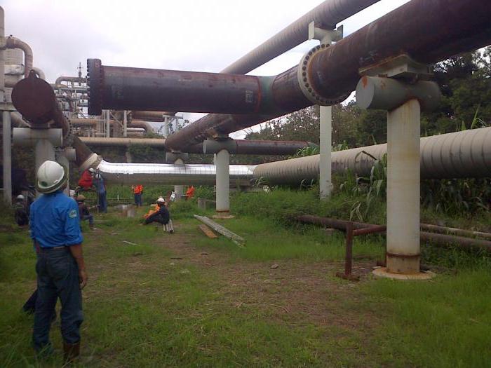
Work methodology
A hydraulic strength test is also carried out to determine the density. During test experiments, the pressure value is set in accordance with the design documentation in kgf/cm 2 . With regard to steel structures, their operating threshold should not exceed 4 kgf/cm 2 when the operating temperature of the system exceeds 400 °C. The pressure value in this case will be equal to the limit from 1.5 to 2.
If the working threshold of the steel structure exceeds 5 kgf / cm 2, then the pressure value will be equal to 1.25. Sometimes this value is determined by a formula that assumes the sum of the workload and the value of 3 kgf / cm 2. If we are talking about products made of cast iron or polyethylene, then the pressure value will be equal to 2 or more. As for non-ferrous metal alloys, the figure is equal to one. To obtain the desired loads, the following types of presses are used:
- operational;
- drive gear;
- mobile plunger;
- manual (piston);
- hydraulic.
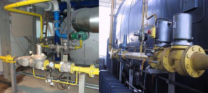
Testing
Strength and tightness tests by the hydraulic method are carried out in several stages. At the first, a press or a hydraulic pump is connected. Next, the brigade installs pressure gauges, and the structure itself is filled with water. It is important to ensure that air is expelled from the system; for this, the air vents are left open. If water got into them, then this means that there is no air left.
Once the system is completely filled with liquid, its surface should be inspected for cracks, leaks and flaws that may occur around the perimeter in the connecting elements. The strength and tightness test at the next stage involves the supply of pressure with its prolonged exposure. The load can be gradually reduced until the indicative values reach the standard level. This will allow you to examine the state of the system again. The pipeline at the next stage is freed from water, and the equipment can be disconnected and removed.
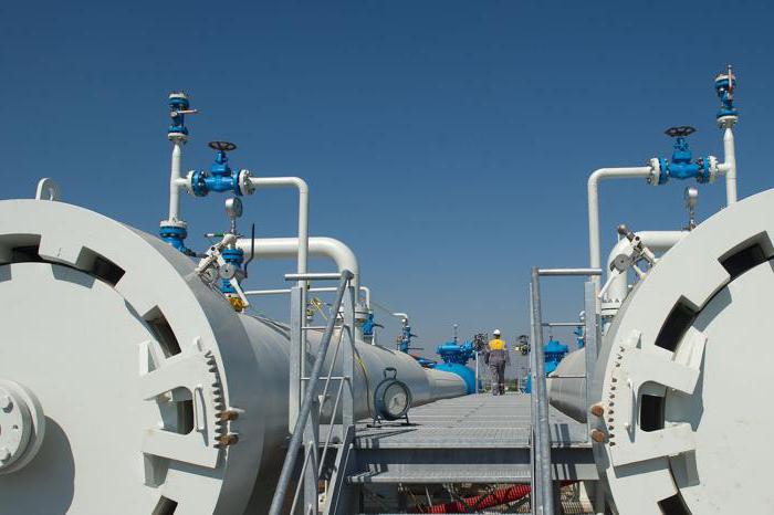
Secondary inspection and final work
If glass compounds are present in the system, then they must be subjected to loads for 20 minutes, but for other materials, 5 minutes will be enough. During the secondary inspection, attention should be paid to adhesions and welds. They should be tapped with a hammer weighing 1.5 kg or less. It is important to ensure access within 20 mm.
When testing elements made of non-ferrous metals, you should use a wooden hammer, the weight of which does not exceed 0.8 kg. Other materials are not subjected to such tapping, as they can be damaged. Hydraulic strength tests are considered successful if the pressure gauge showed no pressure drop, no leaks were recorded, and the welds and flanged connections worked stably, withstanding the load.
The check should be repeated if the results were unsatisfactory, but work should be carried out only after all errors have been eliminated. For hydraulic tests (at low temperatures), substances can be added to the liquid that reduce the crystallization temperature of water. The liquid can be heated, and the pipes can be additionally insulated.
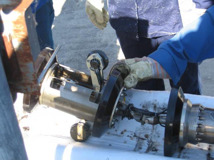
Pneumatic tests
Considering the methods of strength testing, pneumatic testing should be highlighted. It is used to test strength and/or density. Freon and ammonia products are not hydraulically tested; in this case, only pneumatic testing is used.
Sometimes it happens that hydraulic studies cannot be applied. This can happen when the air temperature drops below zero or there is no water in the area. If there is a requirement to use air or inert gases, then hydraulic tests cannot be applied.
Pneumatic testing should also be used when high stresses are observed in the supporting structures and pipelines due to the impressive mass of water. For the implementation of such tests, an inert gas or air is used. Mobile compressors or a compressed air network should be used.
Tests for strength and density require compliance with the pressure and the length of the divisions. Thus, if the diameter is 2 cm, then the pressure should be equal to 20 kgf / cm 2. If the diameter varies from 2 to 5, then the pressure should be 12 kgf / cm 2. When the diameter exceeds 5 cm, the pressure should be 6 kgf/cm 2 . If the project requires it, other values can be used.
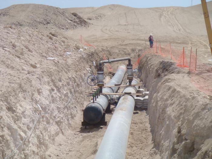
Helpful information
Above-ground structures made of glass and cast iron do not pass pneumatic tests. If the steel system has cast iron fittings, then inert gas or air can be used for testing, as an exception, parts from
Work procedure
Carrying out strength tests by the pneumatic method involves filling the pipeline with air or gas at the first stage. Then the pressure rises. When the level rises to 0.6, you can proceed to inspect the area to be checked. This is true for structures in which the working pressure indicator reaches 2 kgf / cm 2.
During the inspection, the load should be increased. However, tapping with a hammer those surfaces that are under load is unacceptable. On final stage the system is inspected under operating loads. Testing the tensile strength of welded joints and seams, flanges and glands involves the application of a soap solution.
If the system transports flammable, poisonous, toxic substances, then the tightness test is supplemented by a tightness test. To do this, the pressure drop is studied in parallel. It is important to check all equipment that is connected to the system. If, during the strength test, the pressure on the pressure gauge did not decrease, and sweating and leakage were not detected in the glands and connecting seams, then the result is considered satisfactory.
Information about test reports
When tests are carried out Building company or commission, the following documentation is submitted:
- executive scheme;
- test site design;
- welding log;
- journal of insulation works;
As an additional application, there are certificates for parts and pipes, as well as passports for equipment. The result of testing a separate section is an act.
Based on the results of the investigation of the leak, the commission draws up an act, materials are attached to it, which should contain:
- name of company;
- composition of the commission;
- information about test parameters;
- certificate for a broken (defective) pipe;
- information about the design of the pipeline;
- extract from the journal of welding works;
- elevation mark of the break point;
- act of production and acceptance of construction and installation works.
The act of testing the pipeline for strength is drawn up taking into account the current regulations. It necessarily implies an indication of the composition of the commission, the timing of the work and the conclusion, the signatures of the responsible persons. From these documents it will be possible to find out at what parameters the tightness test was carried out. This should include not only pressure, but also the total length of the system. The act of testing pipelines for strength will contain the name of the devices used, other equipment, as well as their installation locations and the length of the section from which water was removed after the test.
Conclusion
Testing of pipelines and evaluation of the results must be carried out exclusively by qualified personnel. They must receive job descriptions and have relevant skills. It is important to remember that testing the pipeline for strength and tightness should be carried out in a timely and thorough manner, because this is the only way to avoid accidents, losses and even accidents.


