Life is impossible without water. Water supply systems for settlements and individual buildings can be called methods of ensuring life support. And drainage is an integral part of them.
All plumbing fixtures and pipes that are used to remove human waste and recycled water form an internal sewer system. According to the network, it is limited by the walls of buildings, exits up to the first inspection well. Typically, wastewater is discharged by gravity, but, if necessary, pumps are used for transfer.
Building sewerage includes the following types:
- Household – K1.
- Industrial - K3.
- Stormwater (includes drains from the roofs of houses) - K2.
- United – K1+K3.
Household network K1
The entire sewerage complex of a residential building is called a utility-fecal, or utility-household, and is designated in design and regulatory literature as sewerage K1.
This network unites plumbing receivers, such as bathtubs, sinks, sinks, toilets, bidets, etc., used for sanitary and hygienic purposes. Receiving devices are used, such as funnels, trays, ladders, and sewer pipes connecting them.
A mandatory part of plumbing fittings is a hydraulic valve. This is a U-shaped siphon half filled with water. This simple technique creates a water barrier that prevents gases from flowing back into the room. Toilets and drains are structurally made with valves; they are connected to other appliances after the drain holes.
Plumbing receivers are connected to outlets through which household wastewater enters the sewer network.
Sewage scheme K1
The pipeline part includes horizontal sections laid with a slope. They flow into risers - vertical sections that combine drains and lead them to the collector. The connection of various sections is made using shaped parts that ensure a change in the direction of the pipelines and their deflection.
A collector is a pipeline laid horizontally with a large slope, connecting the sewage system of a building with the complex of a populated area.
Ventilation piping is an essential part of the plumbing system. They run vertically and are connected to the drainage system. Ventilation helps stabilize the pressure in the sewer system. When designing drainage in small areas, drainage ventilation is provided by air draft, which is a consequence of heating the risers by the internal heat of the premises.
For installation of a household drainage network can be used different types pipe products, the use of which is regulated by SNiP. In the case of waste disposal by gravity, cast iron, asbestos-cement, concrete, reinforced concrete, plastic, and glass pipes are recommended.
When implementing pressure discharge, cast iron, reinforced concrete, plastic or asbestos-cement pipes can be used. For the ventilation part, in addition to cast iron, SNiP allows the use of asbestos-cement pipes, polypropylene, and PVC pipes.
Sections of Ø 50 mm are used as outlets from appliances other than the toilet. Toilet outlets are made with Ø 110 mm. The dimensions of the elements of the entire network are determined by calculations carried out during the design of the sewer system.
Sewer K1 has its own outlet, which is arranged at an angle of 90⁰ to the outer walls, buried to a level slightly higher than the base of the foundation. If there is a basement, the release is performed above the basement floor.
The building's sewerage system is connected to the public sewer system. In the case of a country cottage, it is possible to organize a shambo sewer system, when waste is discharged into a receiving pit on the site and is periodically pumped out and removed. In this case, you should organize vehicle access to the drainage pit.
Compliance with all standards and high-quality installation of household wastewater disposal is a guarantee of reliable operation of the entire wastewater disposal unit.
Storm sewer K2
To drain rainwater, they arrange storm drainage– K2. It represents a plumbing system of funnels, gutters, pipes, filters for purifying wastewater from sand. Open type structures are most often used. Drainage is carried out using open gutters or channels.
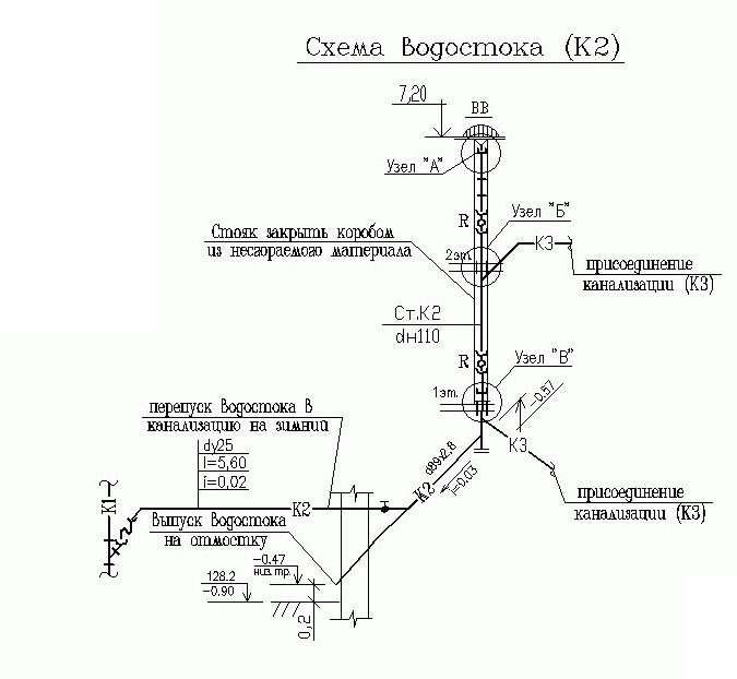
Sewage scheme K2
They transport water flows to the underground part of the complex. For drainage installation use PVC pipes, including corrugated pipes with a smooth inner surface, asbestos-cement pipes.
Properly arranged and designed in accordance with technical regulations, K2 sewerage will protect the building from subsidence and cracking of walls. Upon completion of installation, the system must be tested by an organization that has the appropriate license.
Industrial treatment and wastewater disposal K3
Sewerage K3, used for the removal of industrial waste, is called industrial. Unlike household water, it also contains the necessary treatment facilities. All process wastewater can be divided into two groups: lightly contaminated, which does not require treatment, and contaminated, which cannot be discharged into water bodies without preliminary treatment.
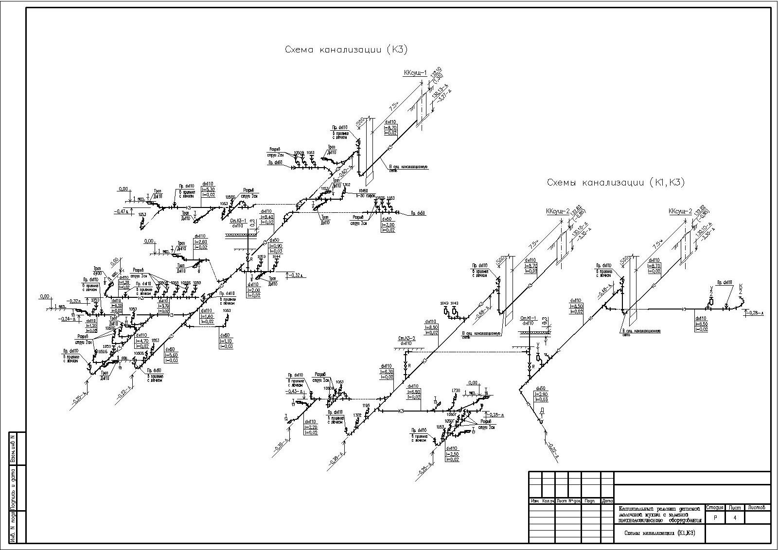
Sewage diagram k3
Since technological waste may have various inclusions depending on the type of production, it may contain salts heavy metals, phenols, toxic substances, etc. The presence of such inclusions determines the use of different structures of engineering communications. Such a structure may consist of:
- Plumbing receivers for drains.
- Diversion structures of industrial buildings.
- Treatment facilities.
- Pumping pumping unit.
- Release to the utility network.
When organizing this type of wastewater disposal, special attention is paid to treatment facilities. Depending on the degree and type of contamination, entire blocks or individual elements can be used. Wastewater treatment is regulated by regulatory technical documents.
Testing wastewater for the content of harmful substances and determining the permissible concentration is regulated by GOST requirements.
The sewerage system is a complex set of engineering equipment, including, in addition to plumbing fixtures, powerful pumping units and modern cleaning devices. Properly installed plumbing and waste disposal improves environmental situation settlements.
(Document)
n1.doc
Legend
– visible section of pipeline B1 (open installation).
– invisible section of pipeline K1 (hidden gasket).
– intersection of pipes.
– water tap.
– watering tap.
– float valve of the toilet cistern.
– faucet for sink or washbasin.
– mixer with shower net.
– common mixer for bath and washbasin.
– shut-off valve (diameter 15, 20, 25, 32, 40 mm).
– valve (diameter 50 mm or more).
- Check Valve.
– water meter (water flow meter).
– pressure gauge.
– centrifugal pump.
– vibration insert (reinforced rubber hose).
- kitchen sink.
- wash basin.
![]() - bath.
- bath.
- toilet with oblique outlet.
– floor drain with siphon (hydraulic seal).
– bell-type drainage funnel (for unused roofs).
– flat drain funnel (for roofs in use).
– bell-shaped sewer pipe.
– transition pipe (usually for transition from 50 mm to 100 mm).
– elbow (for turning sewerage pipelines by 90°).
– bend (for turning sewerage pipelines by 135°).
– straight tee (for risers).
– oblique tee (mainly for horizontal sections).
– straight cross (for risers).
– oblique cross (mainly for horizontal sections).
– crank type siphon (under washbasins and sinks).
– bottle-type siphon (under washbasins and sinks).
– bath siphon.
– revision.
Internal water supply of buildings
The internal water supply of buildings is a system of pipelines and devices that supply water inside buildings, including the water supply input that is located outside.
The internal water supply includes:
1) pipelines and connecting fittings (fittings);
2) fittings (taps, mixers, valves, gate valves, etc.);
3) instruments (pressure gauges, water meters);
4) equipment (pumps).
Symbols for internal water supply see above.
Classification of internal water supply systems
The classification of internal water supply systems is shown in Fig. 1.
Rice. 1
Thus, indoor plumbing is divided primarily into cold (C) and hot (T) water supply. On diagrams and drawings in domestic documentation, cold water pipes are designated by the letter of the Russian alphabet B, and hot water pipes by the letter of the Russian alphabet T.
Cold water pipes have the following varieties:
B1 - domestic drinking water supply;
B2 - fire water supply;
B3 - industrial water supply (general designation).
A modern hot water supply must have two pipes in the building: T3 - supply, T4 - circulation. In passing, we note that T1-T2 designate heating systems (heating networks), which do not relate directly to the water supply system, but are connected to it, which we will consider later.
Water pipes
All indoor water pipes usually have the following internal diameters:
15 mm (in apartments), 20, 25, 32, 40, 50 mm. In domestic practice, steel, plastic and metal-polymer pipes are used.
Galvanized steel water and gas pipes in accordance with GOST 3262-75* are still widely used for drinking water supply B1 and hot water supply T3-T4. Since September 1, 1996, amendment No. 2 of SNiP 2.04.01-85 recommended for the listed water supply systems to primarily use plastic pipes made of polyethylene, polypropylene, polyvinyl chloride, polybutylene, metal-polymer, and fiberglass. It is allowed to use copper, bronze, brass pipes, as well as steel pipes with internal and external protective coating against corrosion.
The service life of cold water supply pipes must be at least 50 years, and hot water supply pipes must be at least 25 years. Any pipe must withstand an excess (gauge) pressure of at least 0.45 MPa (or 45 m of water column).
Steel pipes are laid openly with a gap of 3-5 cm from building structure. Plastic and metal-polymer pipes should be laid hidden in baseboards, grooves, shafts and channels.
Methods for connecting water pipes:
1) Threaded connection. At the joints of pipes, shaped connecting parts (fittings) are used - see below. Threading on galvanized pipes is carried out after galvanizing. Pipe threads must be protected from corrosion by lubricant. Way threaded connection reliable, but labor-intensive;
2) Welded connection. Less labor-intensive, but destroys the protective zinc coating, which must be restored;
3) Flange connection. It is mainly used when installing equipment (pumps, etc.);
4) Adhesive connection. Mainly used for plastic pipes.
Shaped parts (fittings)
Shaped parts (fittings) are mainly used for threaded connections of water pipes. They are made of cast iron, steel or bronze. Here are the most commonly used fittings:
- couplings (butt connection of pipes of equal or different diameters);
Angles (rotate the pipe by 90);
Tees (lateral pipe connections);
Crosses (lateral pipe connections).
Plumbing fittings
Plumbing fittings are used:
Water taps (water taps, bath taps, float valves for toilet flush tanks);
Mixing unit (faucets for sink, washbasin, common for bathtub and washbasin, with shower net, etc.);
Shut-off (valves for pipe diameters 15-40 mm, valves for pipe diameters 50 mm and more);
Safety ( check valves- placed after the pumps).
For symbols of water fittings, see above.
Devices
Plumbing fixtures:
Pressure gauges (measure pressure and pressure);
Water meters (measure water flow).
For symbols of devices, see above.
Equipment
Pumps are the main equipment in the water supply system. They increase the pressure (pressure) inside the water pipes. The vast majority of water pumps are currently powered by electric motors. Pumps are most often used of the centrifugal type.
For pump symbols, see above.
DOMESTIC DRINKING WATER PIPELINE B1
Household drinking water supply B1 is a type of cold water supply. This is the main water supply in cities and towns, which is why it is given the number 1. In its name, the word “household” comes first, since the main volume of water - more than 95% - is used in buildings for household needs and only less than 5% - for a drink. For example, per inhabitant large city daily water consumption rate cold water, according to SNiP 2.04.01-85, is about 180 l/day, of which on average about 3 liters are spent on drinking.
SNiP 2.04.01-85 (as amended). Internal water supply and sewerage of buildings
Water quality requirements B1
Requirements for water quality in drinking water supply B1 can be divided into two groups:
Water must be potable, according to GOST 2874-82*;
The water should be cold, that is, with a temperature t +8 ... +11 С.
Standard for drinking water contains indicators of three types:
1) PHYSICAL: turbidity, color, smell, taste;
2) CHEMICAL: total mineralization (no more than 1 g/liter - this is fresh water), as well as the content of inorganic and organic substances no more than maximum permissible concentrations (MAC);
3) BACTERIOLOGICAL: no more than three bacteria per liter of water.
The water temperature within t +8 ... +11 С is achieved due to the contact of the underground pipes of the external water supply with the ground, for which these pipes are not thermally insulated underground. External water supply is always laid at depths below the soil freezing zone, where temperatures are positive all year round.
Elements B1
We will consider the elements of the drinking water supply system B1 using the example of a two-story building with a basement (Fig. 2).
Rice. 2. Elements of the drinking water supply system B1:
1 - water supply input;
2 - water metering unit;
3 - pumping unit (not always);
4 - water distribution network;
5 - water riser;
6 - floor-to-floor (apartment-by-apartment) water supply;
7 - water supply and mixing fittings.
Water supply inlet
The water supply inlet is a section of an underground pipeline with shut-off valves from the inspection well to external network to the outer wall of the building where water is supplied (see Fig. 2).
Each water supply inlet in residential buildings is designed for a number of apartments of no more than 400. On diagrams and drawings, the inlet is designated, for example, as follows:
Input B1-1.
This means that the input relates to the drinking water supply system B1 and the serial number of the input is No. 1.
The depth of the water supply pipe is taken according to SNiP 2.04.02-84 for external networks and is found by the formula:
H hall = H frozen + 0.5 m,
where H frozen is the standard depth of soil freezing in a given area; 0.5 m - half a meter margin.
Water metering unit
A water meter unit (water meter frame) is a section of a water pipe immediately after the water supply is introduced, which has a water meter, pressure gauge, shut-off valves and bypass line (Fig. 3).
The water metering unit should be installed near the outer wall of the building in a convenient and easily accessible room with artificial or natural lighting and an air temperature of at least +5 °C in accordance with SNiP 2.04.01-85.
The bypass line of the water metering unit is usually closed, and the fittings on it are sealed. This is necessary to measure water through a water meter. The reliability of the water meter readings can be checked using a control valve installed after it (see Fig. 3).
Pumping unit
A pump installation on the internal water supply is necessary when there is a constant or periodic lack of pressure, usually when water does not reach the upper floors of the building through the pipes. The pump adds the necessary pressure in the water supply. The most commonly used pumps are centrifugal pumps driven by an electric motor. The minimum number of pumps is two, of which one is a working pump and the other is a reserve pump. The pumping installation diagram for this case is shown in axonometry in Fig. 4.
Pipelines can be attached:
With support on walls and partitions in the areas of mounting holes;
With support on the basement floor through concrete or brick pillars;
Supported by brackets along walls and partitions;
Supported by hangers to the ceilings.
In basements and technical undergrounds, pipes 15, 20 or 25 mm are connected to the water distribution networks, supplying water to watering taps, which are usually led out into the niches of the basement walls at a height above the ground of about 30-35 cm. Along the perimeter of the building, watering taps are placed in increments 60-70 meters.
Water risers
Anyone is called a boner vertical pipeline. Water risers are placed and designed according to the following principles:
1) One riser for a group of nearby water distribution devices;
2) Mainly in bathrooms;
3) On one side of a group of closely located water fittings;
4) The gap between the wall and the riser is 3-5 cm;
5) At the base of the riser provide shut-off valve.
Floor connections B1
Floor-to-floor (apartment-by-apartment) supply lines supply water from risers to water dispensing and mixing fittings: taps, mixers, float valves of flush tanks. The diameters of the eyeliners are usually taken without calculation 15 mm. This is due to the same diameter of the water supply and mixing fittings.
A shut-off valve 15 mm and a VK-15 apartment water meter are installed directly next to the riser on the supply line. Next, the pipes are brought to the taps and mixers, and the pipes are laid at a height of 10-20 cm from the floor. In front of the flush tank, an additional valve is installed on the supply line to manually adjust the pressure in front of the float valve.
Water taps and mixing fittings
Water taps and mixing fittings are used to obtain water from the water supply. It is installed at the ends of the supply pipelines at a certain height above the floor, regulated by SNiP 3.05.01-85. For example, a common mixer for a washbasin and bathtub is installed at the level of the top of the washbasin at a height above the floor of 850 mm.
FIRE-PROOF WATER PIPELINE B2
Fire-fighting water supply system B2 is designed for extinguishing fires with water in buildings. According to SNiP 2.04.01-85, the following buildings must have the B2 system:
1) residential buildings of 12 or more floors;
2) office buildings of 6 or more floors;
3) clubs with a stage, theaters, cinemas, assembly and conference halls equipped with film equipment;
4) dormitories and public buildings with a volume of 5000 m3 or more;
5) administrative buildings of industrial enterprises with a volume of 5000 m3 or more.
Classification of fire-fighting water pipelines
Fire water supply is divided into three types (Fig. 5).

FEDERAL STATE EDUCATIONAL INSTITUTION
HIGHER PROFESSIONAL EDUCATION
"OMSK STATE AGRARIAN UNIVERSITY"
IN AND. Sologaev
SANITARY
BUILDING EQUIPMENT
Tutorial
Omsk
Publishing house OmSAU
Reviewers:
Doctor of Technical Sciences, Professor N.S. Galdin
(Siberian State Automobile and Highway Academy),
Candidate of Technical Sciences B.A. Kalashnikov
(Omsk State Technical University)
The work was approved by the editorial and publishing council of the university as a teaching aid for students in the specialty " Engineering systems agricultural water supply, watering and drainage." All copyrights reserved.
Sologaev V.I.
Sanitary equipment of buildings: Tutorial. – Omsk: OmSAU Publishing House, 2010. – 60 p.
The textbook contains the necessary minimum knowledge on sanitary equipment for residential, public, industrial and agricultural buildings. The internal systems of water supply, water disposal (sewerage) and gas supply are considered.
The manual is part of a comprehensive multivariate educational system on this subject, developed by the author. It can be used in traditional forms of training: with a teacher (face-to-face); independently (in absentia), as well as in the latest educational technologies: locally on personal computer; remotely in the corporate network of the university; remotely on the Internet.
The book is intended for teachers and students of full-time and part-time education. It can be useful to builders and installers, as well as workers in housing and communal services in cities and villages of our country.
Il. 19. Bibliography. 25. Adj. 2.
ISBN © Sologaev V.I., 2010
Preface ……………………………......................……………… 5
Introduction …………………………………….................……………… 7
Conventions and abbreviations ………...........…………….. 8
Internal water supply ………………………............……………. 11
Classification of internal water supply systems………….........…… 11
Water pipes…………………………………………….…….. 12
Shaped parts (fittings) ………………….........…….. 13
Plumbing fittings…………...................................………… 13
Instrumentation……...................................………. 13
Equipment on the water supply system……................................................……. 14
Domestic drinking water supply B1 ……….................................. 14
Requirements for water quality B1 ....................................................... 14
Elements B1…….................................................. .....…...……. 15
Input of water supply system…..................................…..……. 16
Water meter unit…………….....................................................… 16
Pumping unit…………..................................................... 17
Water distribution network………………………. 18
Water risers…………......................………. 18
Floor-to-floor connections…………...................................…… 19
Water dispensing and mixing fittings ........................ 19
Fire water supply B2…………........................….. 20
Classification of fire-fighting water pipelines……...… 20
B2 systems with fire hydrants ...................................... 21
Semi-automatic deluge units……….......… 21
Automatic sprinkler systems……..........……. 22
Industrial water supply B3…………………............….. 22
Water supply for agricultural buildings………........………. 24
Hot water supply T3-T4………………………..........…… 25
Requirements for water quality T3-T4 ………….................….. 25
Classification T3-T4 …………………………......…….. 25
Elements T3-T4 ……………........................………...……. 27
Installation of internal water pipes………………………... 28
Testing of internal water pipes………………...........….. 29
Operation of internal water supply systems……………..........….. 30
Reconstruction of internal water pipelines………….....…...….. 30
Hydraulic calculation of internal water pipelines…….....….. 31
Internal sewerage …………………………….........………. 34
Classification internal sewerage ……...........………… 34
Sanitary fixtures and wastewater receivers... 35
Siphons and hydraulic valves…………………........…..... 35
Sewage socket pipelines…….....…...…… 36
Connecting fittings ……….................................…. 37
Devices for cleaning the network……................................................……. 38
Domestic sewerage K1 ...................................................... .....….. 39
Elements K1…………................................................... ...………. 39
Rainwater drainage system K2 ............................................................... .......... 41
Elements K2………………….................................... ....... 41
Drainage of buildings……………………............................................ .42
Industrial sewerage system K3…………………….............. 44
Elements K3………………….................................... ....... 44
Sewage of agricultural buildings………………....... 45
Garbage chutes of buildings …………………………………………... 46
Elements of waste chutes…………......................………. 46
Installation of internal sewerage………………….................... 47
Testing internal sewerage………………………......48
Operation of internal sewerage……………........…….. 48
Reconstruction of internal sewerage………………......….. 49
Hydraulic calculation of internal sewerage……...…….. 50
Domestic gas supply …………………………......…………. 52
Classification of internal gas supply………….....…… 52
Elements of internal gas pipelines G1………...............…….. 53
Bottled gas supply……………………............…………. 53
Gas supply to agricultural buildings…………….…. 53
Installation of internal gas pipelines………………...….. 53
Testing of internal gas pipelines………………...........….. 54
Operation of internal gas supply……………..…….. 54
Reconstruction of internal gas supply………………….. 54
Hydraulic calculation of internal gas pipelines………..….. 55
Conclusion ……………………….................................……………. 55
Application ………………………….................................……...…. 56
Checklist ……….................................................. 56
Literature……………………………….................................……. 59
Preface
This book is intended as a training manual and, at the same time, as a reference to the regulatory literature on water supply, sewerage and gas supply of buildings. Her style is the short, telegraphic style of student notes. The main provisions for arranging sanitary equipment in buildings are set out in close intertwining with practice.
The training course “Sanitary equipment of buildings and agricultural production” consists of three sections:
1. Internal water supply.
2. Internal sewerage.
3. Internal gas supply.
In parallel with the lectures, practical classes are held on course design(course work).
After defending the course work, the student is examined for the entire course. The exam is taken on a computer. Within a period of no more than 10 minutes, the student must choose the correct answer options from 10 proposed questions in his opinion. Each question has 5 answer options. Only one of them is correct. If you answer without errors, you will be given an “excellent” rating. With one mistake - “good”. With two errors - “satisfactory”. Three or more errors are “unsatisfactory.”
This tutorial;
A manual for designing coursework;
Exam;
This material can be written in computer classes University at the Faculty of Water Engineering. Another (best) option is to record files via the Internet from the author’s website (the most recent information):
Having this minimum, with a thoughtful attitude towards studying, you can complete coursework and pass the exam with almost no reference to additional literature. The ideal option in this case is to have a home personal computer.
If you don’t have a personal computer yet, you can prepare in the computer classes of the university. They always have scheduled time for independent work.
As already mentioned, it is better to prepare for the exam in advance. The fact is that the electronic exam is not only an objective control of knowledge. It is a self-learning program.
Read this book carefully from beginning to end. Please note that there is a checklist at the end of the book (see appendix). After that, run the exam file. Initially, take the exam by reading the correct answer options from this book. Aim for an “excellent” answer. When you begin to pass the exam, put the book down and take it meaningfully from memory. This will be self-learning.
At the same time, make the most of the traditional method of teaching in the form of classroom lessons with a teacher. Learn through lectures and practical exercises. Bring additional literature, for example, etc. Do not forget about the latest teaching technologies:
Locally on a personal computer;
Remotely in the corporate network of the university;
Remotely on the Internet.
The first option distance learning is the use of the university's corporate network. For this purpose, the Lotus Notes electronic knowledge base is installed in computer classes. Enter your login password in small Latin letters:
After this, various e-courses will become available, including “Building Plumbing.” The advantage of working in Lotus Notes is the availability of a rich database (SNiPs, GOSTs, reference manuals, etc.).
The second option for distance learning uses the Internet. Training also takes place using Lotus Notes, which can be launched from the OmSAU website:
Introduction
Building plumbing is the devices and pipelines for supplying water and gas and discharging wastewater. In other words, this is the internal water supply, sewerage and gas supply of buildings. The above is the subject of our course “Sanitary equipment for buildings and agricultural production”. The short name is plumbing.
The relevance of studying this subject is undeniable. These are life support systems. Obtaining water, preparing food and draining wastewater is necessary for both people and animals. Plumbing is an integral part of most buildings. The goal of its development is to improve healthy living conditions in buildings.
The student’s tasks are to study the basics of plumbing, the features of its design, installation, operation and reconstruction. First of all, the student must know the regulatory requirements for sanitary equipment in our country.
It is quite difficult to read SNiPs and GOSTs on plumbing without preparation. It's better to read this book first. This will provide the reader with the necessary knowledge base on sanitary equipment. This book is in many ways a printed analogue of the author’s lectures. Therefore, it is the most intelligible and it is better to start studying plumbing with it.
The volume of this book is relatively small. However, the information in it is quite dense. Therefore, you need to read the book slowly and thoughtfully. At the very least, you should read it at least once. This especially applies to part-time students. Full-time students have larger lectures. But in any case, this book will provide the necessary assistance to both in preparing for the exam.
Let's start studying the material.
The author's many years of teaching practice have shown that it is better to start getting acquainted with plumbing with standard symbols and abbreviations (abbreviations). This allows you to achieve maximum mutual understanding of the text and illustrations of the book. Let's expand our horizons on plumbing with the help of standard abbreviations, visual drawings and diagrams that are understandable to everyone.
Conventions and abbreviations
GOST - state standard.
SNiP - building codes and regulations.
SanPiN - sanitary rules and regulations.
B0 - water supply (general designation).
B1 - utility and drinking water supply.
B2 - fire water supply.
B3 - industrial water supply.
K0 - sewerage (general designation).
K1 - domestic sewerage.
K2 - rainwater drainage (internal drains).
K3 - industrial sewerage.
D - drainage.
T3 - hot water supply pipeline.
T4 - hot water circulation pipeline.
G0 - gas pipeline (general designation).
G1 - gas pipeline low pressure up to 0.005 MPa.
St V1-1 - water supply riser B1 in numbering order 1st.
St K1-1 - sewer riser K1 in numbering order 1st.
KV1-1 - water supply well B1 in numbering order 1st.
KK1-1 - sewer well K1 in numbering order 1st.
B1 - visible pipeline B1 (open installation). K1 - invisible pipeline K1 (hidden gasket). D - drainage pipeline. - drainage pipeline (another version of the inscription). - connection of pipelines. - crossing of pipelines without connection. - water tap. - bath tap (cork). - watering tap. - float valve of the toilet cistern. - faucet for sink or washbasin. - mixer with shower net. - common mixer for bath and washbasin. - shut-off valve (diameter 15, 20, 25, 32, 40 mm). - valve (with a diameter of 50 mm or more). - Check Valve. - water meter (water flow meter). - pressure gauge. - centrifugal type pump. - insert (reinforced rubber hose with flanges). - fire hydrant. - deluge sprinkler (on plans). - deluge sprinkler (on sections and diagrams). - sprinkler-irrigator (on plans). - sprinkler-irrigator (on sections and diagrams). - kitchen sink (on plans). - kitchen sink (on sections and diagrams). - washbasin (on plans). - washbasin (on sections and diagrams). - bath (on plans). - bath (on sections and diagrams). - toilet (on plans). - a toilet with an oblique outlet (on sections and diagrams). - gangway (on plans). - ladder (on sections and diagrams). - bell-shaped drain funnel (on the plans). - bell-shaped drain funnel (on sections and diagrams). - the drain funnel is flat (on sections and diagrams). - bell-shaped sewer pipe. - transition pipe (from smaller to larger diameter). - elbow (angle of rotation 90°). - bend (angle of rotation 135°). - straight tee (for risers). - oblique tee (for horizontal sections). - straight cross (for risers). - oblique cross (for horizontal sections). - siphon (hydraulic seal) of the cranked type. - bottle-type siphon (hydraulic seal). - siphon (hydraulic seal) for a bath or drain. - revision. - cleaning (oblique tee with plug). - four-burner household gas stove (in plan).Internal water supply
The internal water supply of buildings is a system of pipelines and devices that supply water inside buildings, including the water supply input that is located outside. The internal water supply includes: 1) pipelines and connecting fittings (fittings); 2) fittings (taps, mixers, valves, gate valves, etc.); 3) instruments (pressure gauges, water meters); 4) equipment (pumps). The classification of internal water supply systems is shown in Fig. 1.
Thus, the internal water supply is divided primarily into cold (C) and hot (T) water supply. In diagrams and drawings in domestic documentation, cold water pipes are designated by the letter of the Russian alphabet B, and hot water pipes by the letter of the Russian alphabet T. Cold water pipes have the following varieties: B1 - domestic and drinking water supply; B2 - fire water supply (with fire hydrants); B3 - industrial water supply (general designation). A modern hot water supply must have two pipes in the building: T3 - supply, T4 - circulation. In passing, we note that T1-T2 designate heating systems (heating networks), which do not relate directly to the water supply system, but are connected to it.


