What do you need to know when installing process pipelines? What documents need to be collected? All this is prescribed by special rules (SNiP) and GOSTs. Installation of process pipelines is a very long and complex process, in which more than one authority is involved.
The process pipeline is the most important component, without which no oil depot can function. It provides reception, distribution and transportation of oil and petroleum products. Working in various unfavorable conditions, the process pipeline is subject to corrosion, periodic overheating and cooling.
Since the building process pipeline is very expensive, then first of all attention is paid to purchasing the latest and high-quality equipment. Savings and reduction of oil (petroleum product) losses depend on this. For the installation of such structures, specialists with in-depth knowledge of the rules and regulations for pipeline construction are involved.
What are pipelines for?
Pipeline is a structure that consists of pipes, measuring instruments, fasteners, supports, gaskets, and other parts and is intended for the distillation of oil (petroleum products).
Technological - pipeline, which is located on the territory of the oil depot. This pipeline transports not only petroleum products, but also their waste.
Main characteristics
The internal diameter of the flow section is the main component of any pipeline. A certain amount of oil passes through such a section at certain pressures, temperatures, and speeds.

Technological pipelines are characterized by several concepts (categories).
- Conditional pass.
- Conditional pressure.
- Operating pressure.
In the process of constructing process pipelines, conditional passages are used. This approach allows us to reduce the number of sizes, as well as types of connections that are part of the structure.
Conditional pressure is used to control changes in the strength of compounds during exposure to pressure, as well as the high temperature of the substance that is being distilled. In other words, conditional is the pressure under which the pipeline parts operate. Temperature of the substance ( environment) should be 20°C. Also, GOST 356-80 establishes conditional pressures (a number of them).
The excess pressure under which the pipeline operates, and the temperature is no more than 70°C and no less than 5, is called working pressure.
Classification and types
Pipelines are classified according to the following indicators:
- material;
- conditional pressure;
- temperature;
- aggressiveness;
- location;
- fire hazard;
- type of transported substance;
- impact on the human body.
If we take into account what substance is transported through pipes, then in this case pipelines can be divided into gas, oil, water, for pumping gasoline, and a host of other pipelines.
Based on the material, they are distinguished from steel, non-ferrous metals, cast iron, bimetallic, enameled, non-metallic.
Depending on the pressure of the transported substance, pipelines can be:
- vacuum;
- non-pressure;
- high;
- low;
- without excess pressure.
There are cold, normal and hot pipelines. It depends on the temperature of the substance that is transported. And based on its aggressiveness, they are classified into low-, medium- and non-aggressive. The pipeline can be placed within one workshop (intra-shop), or in different workshops (inter-shop).
Harmful substances act in different ways and are divided into 4 types by GOSTs.
Construction norms and rules (SNiP)
When equipment assembly work takes place, it is simply necessary to comply with the requirements, construction standards and rules (SNiP) of production and safety. Such work is carried out according to the approved estimate documentation. Installation of equipment is carried out using the unit and complete-block installation method.
The installation organization issues documentation that contains technological requirements agreed upon by the customer and the contractor.
- How technological blocks and their components are used.
- Dividing a construction project into units.
- Supply of technological blocks to the installation site.
- Data for calculating the accuracy of alignment work.

The general contractor involves installers in drawing up a conclusion on the construction project and technological configuration. The working conditions are determined by the nodal and complete-block methods, also jointly.
The installation organization receives from the general contractor working documentation with a mark on each copy (drawing) indicating what has been accepted for production. The delivery of pipelines and equipment necessary for the assembly of components is carried out according to schedule. This schedule is agreed with the installation organization. The pipeline assembly work is considered completed when it is completed in accordance with SNiP and the equipment acceptance certificate is signed by a special commission.
According to SNiP, during pipeline construction it is necessary to keep special and general logs for work at each site and draw up technical documentation. The contents of such journals and their types are established by departmental regulations.
Installation work
Before installing equipment and pipelines, preparations are made to organize construction in accordance with SNiP. The customer determines and agrees on a number of points with the general contractor and installation organization. This is essentially a guide to action.
- The terms of delivery and complete set of equipment and materials for the technological unit, unit, line are negotiated.
- Schedules and terms for delivery of the necessary equipment and materials are prescribed.
- Requirements are put forward for installation equipment in accordance with GOST.
- A list of equipment that is installed by the manufacturer’s installation supervision personnel is compiled.
- Delivery of large-sized (heavy) equipment to the construction site.
During preparation for work, the installation organization approves the rules for the installation of pipelines or equipment, prepares sites for the assembly of large equipment, technological units, and communications.
The rules provide for the preparation of lifting equipment, sanitary buildings, vehicles, production bases for assembling communications, technological units, and metal structures. And, also, the implementation of labor protection, environmental and fire safety measures.
How equipment and materials are transferred for installation
Before the equipment is transferred by the customer, the installation organization is presented with accompanying documents in accordance with GOST. If the assembly pipelines are over 10 MPa, then high-quality documents (certificate) are provided for them, and the materials must have supplier certificates.
There are cases when such documents are not available, then the supplier provides a certificate, which is signed by the customer’s management. Accompanying documents are checked for compliance with sizes, brands, and other characteristics of materials used during installation.
Materials (products, equipment) are transferred to the building block in accordance with the drawings. The procedure for such transfer is established by special rules and regulations. Before transferring materials for installation, they are carefully inspected, completeness is checked, compliance with accompanying documents, the presence of a warranty, and its duration. During the inspection, defects identified are for the safety of the customer.
Equipment with an expired warranty period will be accepted for installation only after an inspection. If necessary, defects are eliminated. The results of the audit are recorded in forms (certificates) and other accompanying documents that provide for the rules.
Equipment is stored in accordance with the rules and requirements of the manufacturer. Access to materials is provided, conditions are created to prevent their damage and contamination.
Installation of process pipeline
Process pipelines are connected only to equipment mounted on supports. Such connection must be without distortions or tension. Before installing the prefabricated parts, all nuts must be tightened and joints welded.
The design plan provides for deviation during installation supporting structures. It should not exceed 5 mm in both directions for internal pipelines, and 10 mm for external ones.
Those sections that pass through the walls and are in sleeves should not contain joints. Before placing them in the sleeve, the pipelines are insulated and painted, and the gaps are sealed with fire-resistant material.
http://www.youtube.com/watch?v=khJ4cm_luiw Video can’t be loaded: installation of the Northern Khoseday oil pipeline by Standard2 (http://www.youtube.com/watch?v=khJ4cm_luiw)
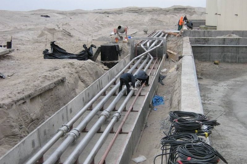
The technology for installing external pipelines largely depends on their purpose and type of laying, the material of the pipes, their diameter, wall thickness, length of the pipes, the presence of ready-made insulation on them and its type (or lack thereof), as well as on the provision of construction installations elements (pipe sections, strands) and other conditions.
Installation of pipelines from any types of pipes (or their sections) involves the need to connect them into a continuous thread. Pipelines on the route are assembled (mounted) from individual elements (pipes) of a relatively short length, and therefore a large number of joints have to be sealed or welded. This slows down and increases the cost of laying pipelines. The laying of pipelines is somewhat facilitated by the preliminary enlargement of pipes into links or sections of two or three and more pipes
Laying pipelines involves installing and assembling assembly units along the route - pipes (or their sections, strands), fittings, compensators and fittings - into the design position. Moreover, the larger the assembly unit, the fewer assembly joints and the easier the assembly of pipelines. The units are assembled and tested, and also covered with a layer of insulation or painted at pipe procurement bases. Industrial technology for laying pipelines provides for the centralized procurement of installation elements and components, their delivery in finished form to the route, preliminary preparation of foundations and support structures for installation, and precise assembly of pipelines.
The composition and sequence of work processes when laying pipelines depend on the type of pipes used (metallic and non-metallic), as well as on the conditions of their installation (in cramped urban or field conditions, on flat or rough terrain, in the presence or absence of natural or artificial barriers, etc.).
Work when laying pipelines is usually carried out in several stages, performed sequentially: checking the quality of pipes; lowering pipes into the trench; centering and laying them in a given direction and slope, securing the pipes in place; sealing joints and checking their quality; testing and acceptance.
Checking the quality of pipes is usually carried out twice - at the manufacturer (according to an established method, sometimes with testing them on a stand) and directly on the route before laying them in a trench. On the route, almost all incoming pipes are subject to inspection and quality control. This is extremely necessary, because when installing a pipeline, especially a pressure one, using at least several or even one low-quality pipe will lead to ruptures and accidents at the place where they are laid. It is very difficult to eliminate them, since this requires stopping the operation of the water pipeline and digging trenches. In case of accidents on water pipelines made of socketed cast iron or reinforced concrete pipes, replacing a low-quality pipe is very difficult. If in such cases it is impossible to correct the defects of a low-quality pipe in the trench, you have to destroy it (which is also not easy) and remove it, and in its place lay an “insert”, most often made of a steel pipe, since it is almost impossible to lay the same socket pipe. If it is possible to correct the defect and put the pipeline into operation, then the “insert” will always be a weak point due to the rapid corrosion of the steel pipe.
On the route, incoming pipes are accepted according to documents (certificates, passports) of the manufacturing plants, confirming their quality. However, defects may occur in pipes due to improper loading, transportation and unloading. Therefore, before laying in a trench, pipes are carefully inspected, their actual quality is checked and rejected if serious and irreparable defects are detected. It is not allowed to lay pipes with cracks, chipped edges and sockets, large deviations from the circumference, i.e. with ovality and other serious defects. The surface of the rubber cuffs and rings used for making pipe joints must be smooth, without cracks, bubbles, foreign inclusions or defects that reduce their performance properties.
The pipes are lowered into the trench using cranes, as well as special lifting devices. Only light pipes (small diameters) are lowered manually, using soft ropes, panels, etc. It is strictly forbidden to throw pipes into a trench. It is relatively easy to lower pipes into a trench with gentle slopes without fastenings; the efficiency of lowering depends only on the right choice pipe laying diagrams and type of installation crane. It is more difficult to lower pipes into a trench if there are fasteners with transverse struts. In this case, the pipes are laid with sequential removal and installation of spacers. All this slows down and complicates the pipe laying process, increases its labor intensity and lengthens the construction period. To speed up and secure this process, large-sized fastenings with vertical panels, horizontal purlins and spacer frames are used, located every 3-3.5 m.
Pipe laying is carried out according to two schemes. In the first scheme, the process is performed in two threads. First, pipelayers, using a crane, lay the pipe on the bottom of the trench and continue to work on final alignment and temporary fastening, and then installers, using a compressor and pneumatic hammers, caulk the pipe joints. In the second scheme, the process is performed in three threads using two taps. Moreover, one of them lowers the pipe and continues to work with the installer team to align and temporarily secure the pipe, and the second one duplicates all these processes for laying the next pipe (second flow); the third flow of caulking (sealing) pipe joints is carried out as in the first scheme. Light pipes are lowered into trenches with fastenings using small-scale mechanization or manually. Pipes or sections should be lowered in strict compliance with safety regulations.
Laying pipes in a given direction and slope (figure below) between two adjacent wells is carried out mainly using portable (running) sights, beacon pins or using a level. Walking sights are used when cleaning the bottom of a trench to the design mark. When laying a pressure pipeline on the cleaned bottom of a trench, the top of the pipes is leveled (leveled), for which purpose sights without protrusions at the bottom are used, installed on the top of the pipes. Therefore, the length of such a sight is reduced by the amount of the outer diameter of the pipes.
Laying pipes in a given direction and slope
1 - cast-off; 2 - constant sight; 3 - sight tracker
For laying gravity sewer pipes according to a given slope, a running sight is used, which has a protrusion at the bottom of the heel, glued at a right angle. When laying pipes, the sighting device with its protrusion is installed vertically on the pipe tray. The pipe is considered to be laid along a given slope to the design marks if the top of the running beam and two permanent sights are in the same plane, visible to the naked eye. The straightness of pipe laying is checked with thread plumbs suspended on an axial wire (mooring). After installing cast-offs and shelves, use a level to determine the marks of the shelves at the ends of the laid area.
The line connecting the points between the centers of the permanent sights on the cast-offs has the same slope as the slope of the pipeline. This line is called the line of sight. A template with a marked axis of the pipeline is inserted into pipes of large diameters, which makes it easier to lay them in a given direction. To speed up work, use inventory metal portable cast-offs. To more accurately comply with the design slope of the pipeline tray, the visual method of an inclined beam of a level or a laser beam (visor) is used. The latter method uses a laser level, which is installed at the beginning of the site.
Gravity pipelines along a given slope can also be laid using a level. The correctness of laying the pipeline in a given direction and slope is finally checked before backfilling pipes and wells by leveling the bottom of the pipe trays and wells, i.e. perform executive shooting. The difference in elevations between the bottom of the wells and the tray at individual points of the pipeline should not differ from the design value by more than the construction tolerance. The straightness of the pipeline between the wells is checked using mirrors that reflect the beam along its axis.
The pipes are secured in place after they are laid either by adding soil or using wedges (for example, when laying heavy pipes of large diameters on concrete foundations).
Sealing of joints is carried out when installing pressure and gravity pipelines from short concrete, reinforced concrete, cast iron, asbestos-cement and ceramic pipes (socketed or smooth with coupling joints). The joints of pressure pipes are usually sealed with rubber rings or cuffs, and gravity pipes - with tarred strands, asbestos-cement mixture, etc. (picture below). Joints steel pipes are welded, and plastic ones are welded or glued.
The tightness and water resistance of socket joints of cast iron pipelines is achieved by sealing the socket gap with tarred or bituminized hemp strands, followed by the installation of a lock made of an asbestos-cement mixture that holds the strand from being squeezed out by hydraulic pressure. Sometimes cement mortar and, in exceptional cases, lead are used instead. IN Lately mastic sealants are used. When sealing joints with self-sealing rubber cuffs, locks are not required.
Joints of reinforced concrete pipes

a, b - bell-shaped; c - folded; 1 - smooth end of the pipe; 2 - asbestos cement; 3 resin strand; 4 - bell; 5 - cement mortar; 6 - rubber rings; 7 - cement mortar or asphalt mastic; 8 - grouting with cement mortar
Sealing socket joints with strands. The hemp strand is inserted into the bell slot until the bell stops to such a depth that there is room left for the lock. Since the thickness of the tow from the strand is slightly greater than the width of the bell slot, it is pushed into the joint using caulk, with which the tow is inserted into the annular gap, first by hand, and then with strong blows of a hammer (for hand-chasing). In mechanical embossing, the tow is compacted using a pneumatic tool. To create the required tightness of the joint, 2-3 strands are usually placed in the gap, and so that their overlaps do not coincide along the circumference. After sealing the joint with a strand, an asbestos-cement lock is installed, laying the asbestos-cement mixture into the gap in layers of rollers (3-4 layers each) and compacting with stampings, striking them hard with a hammer. The sealed joint is covered with damp burlap for 1-2 days, which creates favorable conditions for the asbestos-cement mixture to set and harden.
Sealant mastics are used to seal the butt joints of socketed cast iron pipes when laying pressure sewer pipelines with a maximum operating pressure of up to 0.5 MPa. Most often, polysulfide sealants made from sealing and vulcanizing pastes are used, to which asbestos or rubber crumbs are sometimes added. Mastic-sealants are prepared at the work site 30-60 minutes before their use. The joints are sealed using syringes with manual or pneumatic extrusion of mastic or pneumatic installations. The sealant is introduced into the socket slot using a nozzle, which is attached to the tip of a syringe or hose of a pneumatic installation.
Installation of process pipelines should be carried out in accordance with building codes and regulations, which indicate the basic provisions for the production and acceptance of work on the installation of permanent process pipelines made of carbon and alloy steels, non-ferrous metals and alloys, cast iron, plastics and glass, operating at an absolute pressure of 35 mmHg Art. up to 700 kgf/cm2.
The volume of work on their installation is usually about 50% of the total volume of installation work. The laying of most pipelines is carried out in cramped conditions, at different heights in multi-storey buildings and in open areas, overpasses, in trays, tunnels. In-shop process pipelines are distinguished by a large number of standard sizes, pipeline parts, shut-off control valves, and fastening means used.
So, for example, to complete an intra-shop process pipeline, it is necessary to add up to 42% of the weight of the pipes of various pipeline parts and fittings. The complex configuration of such pipelines causes a large number of connections between pipes, parts and fittings. For every 100 m of pipeline length, on average up to 80 welded joints have to be made.
The use of ready-made units, elements and sections during installation, centrally manufactured using factory parts in pipe procurement shops, allows us to significantly simplify the technology and organization of pipeline installation and turn the construction site into an assembly site. This reduces the volume of welding work previously performed directly at the installation site by 5-6 times. At the same time, the installation time for pipelines is reduced by 3-4 times (considering that they are manufactured in parallel with construction work). With proper organization of work, pipeline components should already be manufactured in workshops and delivered ready-made to the construction site for installation by the time the construction part of the facility is ready.
Before installation of pipelines begins, the following preparatory work must be completed:
- The project and PPR were studied in detail by engineering workers (foreman, work manager, foreman) and all unclear issues were agreed upon with the relevant organizations.
- Assemblies, elements and parts of pipelines, fittings not included in the units, supports and hangers are accepted; their compliance with project requirements or technical specifications is verified.
- The degree of construction readiness of buildings, structures and structures for installation was checked, and the corresponding acts were drawn up. Particular attention should be paid to compliance with the design marks of the pipeline fastening points.
- Equipment for installation of pipelines was accepted: the correct installation of devices and equipment and compliance with the drawings, location, type and dimensions of connecting fittings on the equipment were checked. All deviations from the project must be recorded in the act.
- Pipeline lines are equipped with assemblies, elements and parts, fittings, and auxiliary materials; pipeline lines must be delivered to the installation site.
- Arranged and prepared: platforms for enlarged assembly, scaffolding and devices for working at heights; Electricity has been supplied to power welding stations, power tools, electric winches and lighting of individual installation sites.
- Specialized work teams are staffed and provided necessary tools, fixtures and mounting mechanisms.
- The teams were issued work orders for the upcoming volumes of work.
- Necessary working conditions are provided in accordance with labor safety and health regulations
- Workers were briefed.
The technology for the actual installation of steel pipelines includes the following operations: laying out the pipeline route; installation of supports and suspensions; enlarged assembly of units and blocks; laying, assembly and welding of the pipeline; installation of compensators, fittings, drainage devices, control and automation devices; testing of finished lines, delivery to the customer.
Process pipelines include all pipelines through which raw materials, semi-finished products, and finished products are transported; auxiliary materials; industrial waste from aggressive wastewater. Water supply pipelines at pressures up to 1 MPa, fire water supply, heating, sewerage of non-aggressive wastewater and storm sewer. The reliable and uninterrupted operation of equipment and the enterprise as a whole largely depends on the quality of installation and proper operation of pipelines.
There are two types of pipelines for milk: main, or main, lines through which raw materials and products are transferred between workshops or areas, and communication, connecting trunk lines with technological equipment. For main lines, as a rule, pipelines with a diameter of at least 50 mm, made of stainless steel or glass, and fittings from of stainless steel. Communication pipelines are made only from stainless steel; fittings are allowed from half-bronze.
During installation, the need for daily dismountable or non-dismountable washing of pipelines should be taken into account. In addition, the equipment should be easy to maintain. Therefore, pipelines are located at a height of at least 1.8 m from the floor. Main pipelines are installed parallel to the walls with a slope towards the movement of liquid, and communication pipelines are installed along the shortest path with the least amount of fittings (bends, taps). Connections of pipeline sections subject to dismountable washing should be easy to disassemble, the length of straight sections should not exceed 3 m, which is necessary for the convenience of washing them with brushes. All connections must be strong and tight.
Before the installation of pipelines begins, the documentation (diagrams, specifications) is studied. For enterprises under construction, these documents are developed by the design organization, and they are part of the project documentation; at an operating enterprise they are made up of mechanics and plant technologists.
After studying the documentation in accordance with the specification, the main lines are equipped with fittings and straight sections of pipes.
The actual installation of pipelines for milk is carried out in two stages. First, the places where the pipeline route will be laid are marked and means of their fastening (hangers, brackets) and sleeves are installed in places where they pass through walls and ceilings (Fig. 14.2, a B C). These operations are performed simultaneously with the installation of general purpose pipelines. Then, in the second stage of work, the pipelines are assembled. Before the start of the second stage of installation, all finishing work must be completed in the room.
Marking the pipeline route and installing supports. Pipelines for milk, depending on the length of their straight sections and the viscosity of the transported product, are installed with a slope of at least 1-5%, and the thicker the product, the greater the slope.
Slope is the ratio of the difference between the elevations of two points A And D(Fig. 14.2, G) to the horizontal distance between them AC(hairline). Indicate the slope with a letter I and is usually expressed as a percentage: I= 5%, or / = 0.05. The slope is considered positive for a rising line and negative for a falling line. The direction of movement of the medium in the pipeline, as well as the slope, is indicated by an arrow under the pipeline slope designation (or above it).
A - suspension: 6 - height-adjustable stand; c - console (left) and bracket; d - pipeline route marking diagram: A, B, D - attachment points for pipeline supports; AC - horizontal reference line; AD - pipeline control axis (string)
To mark main lines, they mainly use a hydrostatic level, a plumb line and a steel tape of the appropriate length. Marking begins by marking the pipeline axes on building construction(walls, columns). In this case, it is convenient to use strings that indicate the axes of the pipelines.
Between the starting point A and final WITH pull the horizontal string AC. Knowing the distance AC and slope / = 0.05, find the decrease CD: H= 12 ■ 0.05 = 0.6 m and transfer the string to a point D, Where is it secured? Setting aside distances between supports A, B,D Etc., mark the attachment points for intermediate supports.
Pipelines are attached to the ceiling on hangers (Fig. 14.2, a), to walls and columns on brackets and consoles (Fig. 14.2, a) V), as well as on height-adjustable support posts (Fig. 14.2, b). In this case, it is necessary to take into account the possibility of vibration of pipelines when moving raw materials, products or cleaning solutions through them. Where the pipeline passes through walls, partitions and ceilings, steel sleeves with an internal diameter of at least 125 mm for pipes with a diameter of 36 and 50 mm and 170 mm for pipes with a diameter of 75 mm are installed. The part of the pipeline that will be in the sleeve should not have connections.
According to the markings made, the supports are installed: racks, brackets, consoles. Several lines (“threads”) of pipelines can be mounted on one bracket or console.
Cleaned and washed fittings (taps) are mounted on the supports and lightly secured. Then straight sections of pipelines are laid and pre-attached to the supports and to each other. Check the required slope. The fasteners are finally tightened and a control alignment is carried out.
Communication (piping) pipelines are installed after final alignment and fastening of process equipment. At the same time, they measure with a tape measure and put on the technological diagram of the equipment piping the actual required dimensions of the pipelines, making an allowance of 100 mm for adjustment in place. In this case, the pipelines are collected from the machine or apparatus to the side main pipeline. After final verification of the slopes and straightness of the pipeline axes, the last connecting section of the pipeline on which the allowance was left is adjusted into place.
Installation of stainless steel pipelines. Pipelines are assembled using quick-dismount coupling connections, consisting of a threaded fitting (pipe), a nipple (cone), a union nut and a rubber gasket. The ends of the connected pipes, 30-40 mm long, are degreased, cleaned on the outside with an emery wheel, and on the inside with a file. The end of the pipe is also filed perpendicular to the axis of the pipe. After stripping, the ends of the pipes are washed with a 0.5% solution soda ash, then wipe with warm water and dry. A fitting or nipple is placed on the ends of the pipes all the way and secured by welding. Before installing the nipple, put a union nut on the pipe. For ease of pipeline assembly, markings are applied to the ends of the pipes after installation.
Distance between two adjacent pipeline supports L Determined by the permissible deflection of a two-support beam
Glass pipelines. They are used for main lines that are washed only in-place. To avoid mechanical breakage of pipes during their operation when laying at the bottom, glass pipelines are mounted at a height of at least 2 m.
Heat-resistant glass pipes are supplied up to 3 m long with smooth polished ends, wrapped in thick paper, placed in wooden boxes with soft filling. Before installation, glass pipes and fittings (bends, tees) are kept for 2-3 hours to heat up to room temperature.
The installation sequence for glass pipelines is similar to the installation sequence for steel pipelines. However, glass pipelines practically do not bend, so in order to avoid their mechanical destruction when marking the route, special accuracy must be observed.
Glass pipelines for milk are installed with a slope of 5-10%. Welded consoles are used as supports (Fig. 14.3, a).
To prevent the crane's gravity from being transferred to the glass pipes, it must have two independent supports 7 (Fig. 14.3, b).
After installing the supports on the floor, links are assembled from two or three pipes of the same diameter. Glass pipelines are connected to each other and to fittings using cast iron or aluminum flanges (Fig. 14.3, V) triangular or square in shape, respectively, on three or four coupling bolts 3; apply
A - fastening the glass pipe to the console: 1 - console; 2 - bolt; 3 - clamp; 4 - rubber gasket 5 - glass pipe; 6 - gasket joint; b - mounting of a three-way milk tap on consoles 7; c - flange connection of glass pipes; d - installation of sealing rings at the end of the pipe: 1 - flange; 2 - rubber sealing rings; 3 - bolted connection; 4 - T-shaped gasket; d - cutting a glass pipe: 1 - step-down transformer (220/36 V); 2 - wet sponge; 3 - electrically insulated handle; 4 - nichrome wire; 5 - switch; 6 - glass pipe Also a coupling (threaded) connection with a plastic half-coupling. At flange connection tightness is achieved by installing a T-shaped rubber gasket between the ends of the pipes 4 (Fig. 14.3, G) and two rubber rings 2 (Fig. 14.3, V) at each end of the connected pipes. When assembling pipes, flanges and gaskets must be dry. The flanges are tightened with special pliers. The distance between the assembled flanges should be 8-10 mm; The nuts on the bolts should be tightened evenly. To avoid distortion when assembling glass pipeline connections, they must be fixed with special devices on which the pipes are laid.
Glass pipes are cut in two ways. In the first case, the pipe 6 (Fig. 14.3, d) in the plane of the cut they are wrapped with nichrome wire 4 with a diameter of about 1 mm so that both of its ends at the point where they exit the pipe are no more than 1 mm away from each other. An electric current of 36 V is supplied to the wire through transformer 1, as a result of which the wire heats up to a light yellow color and heats the pipe for 1-2 minutes. After this, the current is turned off, the wire is removed, and the heating area of the pipe is cooled with a wet sponge 2. At the point of heating, a crack forms around the pipe, along which the pipe easily splits. The ends of the pipes are cleaned with a coarse-grained carborundum stone; the angle between the end and the axis of the pipe should be 90°.
When cutting using the second method, the pipe is placed on two pairs of rollers that can rotate freely. Pressing a glass cutter to the pipe in the cutting plane, turn it around its axis, create a crack, break off and clean the end.
The assembled pipe links are placed on supports and fixed. In this case, the smallest distance between the axes of adjacent pipelines should be 150 mm, and from the axis to the wall - 100 mm. The pipe links are secured to the supports with U-shaped clamps 3 (see Fig. 14.3, A) made of strip steel with rubber gasket 4 bolted 2. The bends are secured with two clamps located at an angle of 90°. The clamp nuts are first pre-tightened, then the pipeline links are connected to each other, and then finally tightened. In this case, the tightening force must be such that the pipes can move in the axial direction due to linear expansion when heated. Glass pipelines with stainless steel pipes and taps are connected with stainless steel adapters. To speed up the installation work, it is advisable to carry it out by contract.