The purpose of the mixing unit is to adjust the temperature regime of the heated floor by mixing the liquid from the boiler and the return flow. It is not difficult to create a mixing unit for a heated floor with your own hands. However, when installing, you should strictly adhere to certain actions so that the equipment does not break down in the future.
First of all, you need to find out how the mixing unit for heated floors works. It is used only for water underfloor heating, since it has a mechanism similar to radiator coolant. A typical heating circuit is built according to the following plan - a boiler that heats the liquid, circuits of a heated floor and radiators.
The boiler warms up the coolant to a temperature similar to a radiator, usually 95C. Ideally temperature regime should not be more than 31C. There are several reasons for this, especially that for a comfortable feeling the floor should not be very hot or cold.
Things to take into account:
- type and thickness of the finishing coating;
- the height of the heating floor screed in which the tubes are located.
Accordingly, the most suitable liquid temperature in the pipes should vary from 35C to 55C. However, it is very high in the boiler, and it is prohibited to direct such a temperature into the tubes. Therefore, in order to reduce it, a mixing unit is used at the beginning of the heating system. This is where high and low temperatures mix with water. And the already cooled liquid is transferred to the floor tubes. Using the mixer, the underfloor heating system functions throughout the entire house correctly and without interference.
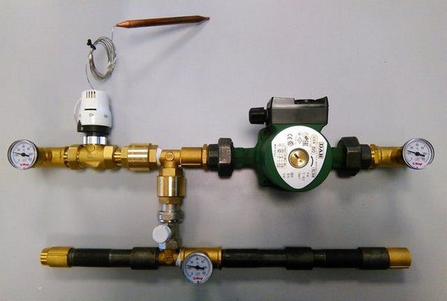
Mixing unit for heated floors
Of course, there are heated floors that work without a mixing unit. But they are equipped with a water heating device that heats the coolant to the optimal temperature.
Mixing node connection plan
The heating floor is connected to the boiler according to a certain scheme, which depends on the heating system:
- 1-pipe;
- 2-pipe.
A single-pipe heating system needs to constantly open the bypass, but a two-pipe heating system does not. The project can be either the most elementary or using a number of complementary elements.

Single-pipe heating system
In any case, thermostats for the manifold group, devices for controlling water flow and valves are installed. Direct mixing can take place at all branches of the collector group, or before them.
How to make a mixing unit with your own hands
The cost of the mixing unit is quite high, so for many it is more profitable to make it yourself. In addition, it is not always possible to find a regulator with the required number of inputs. In this case, you should also purchase combs, which you can install yourself.
In order to assemble a mixing unit for a heated floor with your own hands you will need:
- 2 or 3 way valve;
- special nuts;
- manual air vent;
- return valve;
- clamps;
- ball valve;
- circulation pump;
- tees;
- devices for determining temperature.
Mixing unit for heated floors
The first stage consists of manufacturing the collector. You can do this using 2 methods:
- solder from polypropylene tees;
- twist from tees.
In any case, the diameter of the elements should be ¾ inches. When soldering, the collector will be more expensive, since each branch of the comb must be equipped with an MRN, which has a rather high price. High-quality tees are considered the most suitable material. The most important thing is to choose them wisely. Products with 1 internal and 2 external ends are ideal for a comb. They are twisted together only with the help of tow.
The second stage is to create a hydraulic arrow. You can do it without even using a 3-way tap. A standard control valve, which is used for heating batteries, will be sufficient. In addition to it, you will need 2 tees, as for combs, and 2 connecting nipples with threads on the outside and inside, the length of which should be 0.5 m. Assembly is carried out on tow. To do this, nipples are screwed in on both sides of the tap, and 1 tee is connected to them on each side.
The third stage is the construction of the pump. It is impossible to make a pump unit for a heated floor with your own hands, so they buy it. The pump is mounted at the bottom of the hydraulic needle using detachable connections, which are sold as a set. You can also install it instead of a hydraulic arrow. It will act as its replacement, and will function just as well.
Pumping unit for heated floors
The final stage is the connection with the hydraulic arrow combs. It is best to make detachable connections. When the pump acts as a separate element, you need to buy a pipe. Its length should be equal to that of the pump. It is mounted on the supply, and the manifold is screwed to the pipe. It is for this reason that using a pump instead of a hydraulic arrow is much more economical.
Then the comb is equipped with adjustment valves, Mayevsky or automatic devices for air release. Next, the mixer is placed in a designated area of a special cabinet and connected to the heating system.
The thermo-mixing unit for a heated floor is connected with your own hands using shut-off valves. The connection between the unit and the heating floor occurs in the same way. The first end with the comb at the bottom, the second - towards the top. In order to avoid confusion, you should adhere to a certain layout - the supply and return of one segment must be connected in series. In addition, the electrical supply is connected to the pump.
![]()
Thermal mixing unit for heated floors
Setting up the mixing node
After the installation of the mixer is completed, it is time to check its functionality. As a rule, adjustment takes a lot of time and effort than installing a faucet. However, harmonious calculation allows you to do this with minimal costs.
First of all, the servo drive is removed. This is done so that it does not affect the node during the setup process. The bypass valve is set to the extreme position.
Important! A valve accidentally activated during the adjustment process will cause the result to be incorrect. Accordingly, the mechanism must be given a position in which it will be completely inactive.
Then comes the balancing of the contours of the floor. First, the radiator circuit is closed, that is, the balancing circuit shut-off valve first line. The cap is removed from the valve and, using a hex wrench, it is turned completely clockwise. The lines of the kennel are balanced by special valves. When the mixer has one line, balancing is not necessary.
If necessary, it is carried out using the following steps. The regulators are opened to maximum. The valve closes to the best size in the circuit where flow deviation is greatest.
According to this scheme, the heating line as a whole is regulated. When the flow data gets lost when balancing the lines, they are adjusted again. If the flow rate is not adjusted when the valves are open, then increase the operating speed of the pump.

Pump mixing unit
Next, the pump mixing unit is linked with other heating elements of the system. Why open the balancing shut-off radiator valve, closed before starting the adjustment. Open it to an indicator corresponding to the optimal fluid flow.
Water consumption is controlled using special flow meters. Can also be adjusted via the return stroke in the floor system. Then comes the turn of the bypass valve. To begin with, the valve pressure is set. The parameter should have a value of no more than 10% of the highest pump pressure. This maximum must correspond to the main features of the pump type. The valve is activated if the unit builds up pressure at the lowest fluid flow.
Modifications and design of mixers
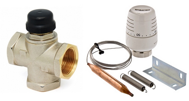
Mixing units as standard include:
- thermostatic and adjustment valve;
- thermostatic head;
- pump;
- temperature device.
There are 2 types of mixer - with 2 and 3 way valves. They mix cold and hot water for the heating floor, which forms a constant circulation.
The 2-way valve is equipped with a thermal head with sensor. The temperature is checked by a sensor in real time, and if necessary, it stops the supply of liquid from the boiler. Hot water is supplied only when it cools down while mixing with the return flow. Two-way valves are designed for rooms no more than 200 m2.\
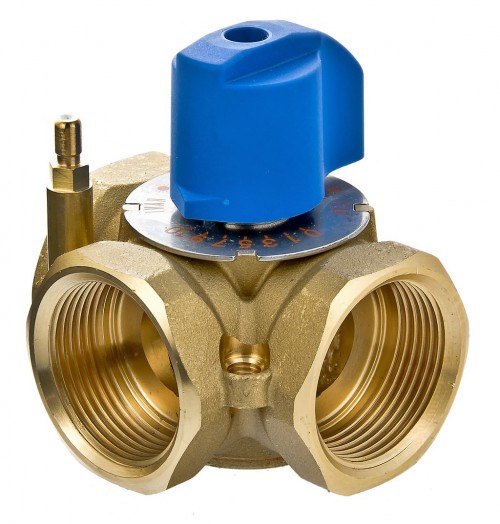
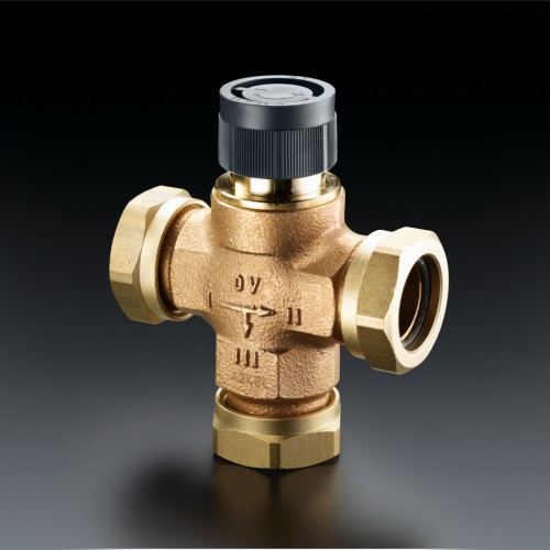
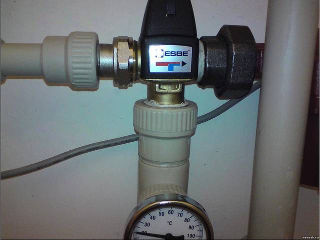
Three way valve
A three-way valve has more flow capacity than a two-way valve. In small rooms, it will not be able to let water into the general system if it is completely open. As a result, this can lead to sudden changes in temperature and rupture of tubes. Thus, the 3-way valve is best suited for spacious and large rooms where systems with a large number circuits and environmental controllers are used.
The modern market offers models that differ in consumer type:
- for installation to a personal standard collector;
- as a group personal node for connecting a system with significant power.
In the latter case, it can be used to connect several systems with low power ratings, or those designed for significant power with 2 to 12 outputs.
Outdoor temperature sensors
These devices are recommended for systems as automated adjustment of the coolant according to weather conditions. For example, if it is cold outside, a signal is sent to increase the temperature of the coolant. When warming is observed, the sensor tells the system that the temperature can be lowered.
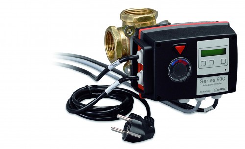
Temperature sensors
The device is designed to rotate 90 degrees. A special controller divides them into 20 sections and monitors the conditions on the street. If the water temperature does not correspond to them, the valve turns the required number of divisions. Of course, you can do all this yourself, but it’s much more convenient with a weather temperature sensor.
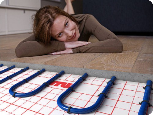
Advantages of heated floors with mixer
A heated floor with a mixing unit has many advantages compared to other heating systems.
Comfort
It is possible due to the supply of heat energy due to radiation, but not convection. In addition, the floor surface and the room are heated evenly. There are no cold bridges or hot radiators in the rooms. All this creates a comfortable and healthy atmosphere, therefore there is no dust. The surface always remains dry and does not create an environment for mold, mites and other harmful microorganisms.
Warm floor with mixer
Economic benefit
Depending on the location of the tubes and the functioning of the heating system, you can save on heating the room. It has been established that residential apartments consume 30% less electrical energy, provided that the ceiling has a standard height. Thus, the consumption of energy resources can reach 50%.
Safety
This is important for rooms where people are constantly present. The operation of a heated floor allows you to avoid burns and other manifestations that may occur when using radiators or convectors.
Hygiene
The water floor system with mixer allows for proper disinfection of the finish coating. The floor can be cleaned with different detergents, water. This heating system is ideal for rooms with specific hygiene requirements. For example, a water floor with a mixing unit is suitable for kindergartens and hospitals.
Warm floors - comfort and convenience
Convenience
For water heated floors, there is no need to install additional devices in the heated room. All necessary elements are installed, as a rule, in storage rooms. Therefore, you can make a wide variety of layouts without allocating space for the unit.
Mixer installation features
A heated floor mixing unit is installed directly next to the heater. When elements hydraulic system are connected by elastic tubes, the mixing unit needs to be firmly mounted on the wall. In addition, before installation, it is necessary to allocate places so that there is free, easy access to the mixer elements.
The control valve must be located in the area of the coolant inlet to the heater. When selecting pipe materials, you should make sure that they will withstand the temperature of the incoming coolant. Therefore, it is advisable to buy polymer pipes. It is also worth remembering that galvanized pipe cannot be used for glycol-water solution. It is better to use locking parts made of bronze and brass, tubes – from black steel, and a pump – from cast iron. Manufacturers prime and paint the steel parts of the entire system on the outside.
Note! It is necessary to select the installation location and connection of the unit taking into account air bubbles that may appear from the boiler circuit outlet device. It is also necessary to completely eliminate the possibility of water and condensed liquid entering live parts of the system.
Mixing unit control valve
Thus, it is advisable to select the mixing unit individually to ensure maximum ease of use of the floor heating system.
It is quite possible to select the system yourself, having first studied all the connection diagrams. However, if the user does not understand anything at all about the components and purpose of the parts, it is best to buy a ready-made design.
Cable underfloor heating can be installed in premises of any purpose, both in an industrial building, an office, and in a living room. For bus...The use of a “warm floor” system for heating rooms has ceased to be an innovation. Many people equip with heated floors, if not the whole house, then individual rooms, for example, a bathroom or living room. Of course, other heating devices are used simultaneously with heated floors, for example, radiators that are familiar to everyone. “Warm floors” belong to low-temperature heating systems, and heating radiators belong to high-temperature ones, therefore mandatory element in a heated floor system there is a heated floor mixing unit. The main function of this node is to mix, as the name suggests. Why is a mixing unit needed, what does it mix with, what is the principle of its operation, as well as the installation and configuration algorithm - we will tell you all this in this article. We will also give examples of working diagrams for installing a mixing unit in a heating circuit and outline the nuances.
Why do you need a mixing unit for heated floors?
It is necessary to immediately clarify that the mixing unit is only necessary for a water heated floor system, since the same coolant flows in it as in the heating radiators. As a rule, the heating system is organized in this way: one boiler heating the coolant, a circuit of high-temperature radiators and a circuit or several circuits of a water heated floor.
The boiler naturally heats the water to the temperature required for high temperature radiators. Most often this is 95 °C, but sometimes radiators are used for temperatures of 85 - 75 °C. According to sanitary standards, the temperature of the floor surface should not exceed 31 ° C, this is due to many reasons, and first of all, with a comfortable stay on the floor covering, so that it is neither cold nor hot. Taking into account the thickness of the floor screed in which the pipes of the “warm floor” system are embedded, as well as the thickness and type of floor covering, the temperature of the coolant in the underfloor heating pipes should be 35 - 55 °C and no higher. It is logical to assume that water cannot be directed directly from the boiler into the underfloor heating circuit, since its temperature is too high. What to do? How to lower the coolant temperature?
It is with in order to reduce the temperature of the coolant at the entrance to the heated floor circuit a mixing unit is used for heated floors. It mixes the hot coolant and the cooler return coolant of the heated floor. As a result, the average temperature becomes lower and coolant is supplied to the circuit. All heating circuits in the house work correctly: hot water is supplied to the radiator circuit at a temperature of 95 °C, and to the heated floor circuit at a temperature of 55 °C.
If you are interested in the question of whether it is possible to do without a mixing unit and in what situations, then we will answer - this is possible. If the heating throughout the house is carried out using low-temperature circuits, and the heat source heats the coolant only for the heating system to a given temperature, then mixing units do not need to be used. An example of such a heating system would be the use of air heat pump. If the heat source heats water not only for heated floors, but also for the shower, the temperature of which is 65 - 75 ° C, then the installation of a mixing unit is mandatory.
How does a mixing unit for a heated floor work?
Conventionally, the operation of the mixing unit can be described as follows: the hot coolant reaches the heated floor manifold and rests against the safety valve with a thermostat; if its temperature is higher than the required one, the valve is activated and opens the cold return flow, mixing occurs - mixing the hot and cold coolant. As soon as the temperature reaches the required values, the valve is activated again and shuts off the supply of hot coolant. We will consider the operation of the node in more detail below, since it can be organized in two ways.
The collector unit for a heated floor serves not only to regulate the temperature of the coolant, but also to ensure its circulation in the circuit. Therefore, the collector unit consists of two main elements:
- Safety valve, which we have already talked about. It feeds the underfloor heating circuit with hot coolant exactly as much as necessary, controlling the inlet temperature.
- Circulation pump, which ensures the movement of water in the heated floor circuit at a given speed. This ensures that the entire area of the heated floor is heated evenly.
In addition to the main elements, the mixing unit may include: bypass, which protects the node from overloads, drainage And shut-off valves And air vents. Therefore, the collector mixing unit can be made different ways depending on the assigned tasks.
The mixing unit is always installed before the heated floor contour, but the location of its installation itself may be different. For example, it can be installed directly in a room with a heated floor, in a boiler room to separate the collectors going to the high-temperature circuit and the low-temperature circuit. If there are many rooms with heated floors, then the mixing units are installed in each room separately or in the nearest manifold cabinet.
The main difference in the operation of mixing units is that they can use different safety valves. The most common are 3-way valves and 2-way valves.
A two-way valve is sometimes also called a feed valve. This valve is equipped with a thermostatic head with a liquid sensor, which constantly monitors the temperature of the coolant entering the heated floor circuit. The head opens and closes the valve, and thus adds or cuts off the supply of hot coolant coming from the heating boiler.
It turns out that the mixing of coolants occurs in this way - the coolant from the return is supplied constantly, and the hot coolant is supplied only when necessary, i.e. its supply is regulated by a valve. In this regard, the heated floor never overheats and its service life is extended. The two-way valve has a low throughput, due to which the temperature of the coolant is controlled smoothly, without sudden jumps.
Most underfloor heating installers prefer to install a water mixing unit with a two-way valve into the underfloor heating. But there is a limitation - it is not advisable to install them if the heated area is more than 200 m2.

The three-way valve combines the functions of a supply bypass valve and a bypass balancing valve. Its main difference is that it mixes hot coolant with cold return inside. Three-way valves are often equipped with servo actuators that control thermostatic devices and weather-compensated controllers. Inside such a valve there is a damper, which is located in a 90 ° zone between the hot coolant supply pipe from the boiler and the return pipe. You can set any position - middle or with a slope to one side, depending on the required ratio of the mixture of return and hot water.
It is believed that this type of valve is universal and indispensable in heating systems with weather-compensated controllers and simply in large-scale systems with many circuits.
The disadvantages of three-way valves should also be noted. Firstly, it is possible that, following a signal from the thermostat, the three-way valve will open and allow hot coolant with a temperature of 95 °C into the heated floor circuit. Sudden temperature changes are unacceptable in the operation of heated floors; pipes may burst from overpressure. Secondly, due to the large flow capacity of three-way valves, even a minimal shift in valve adjustment will result in a significant change in temperature in the circuit.
Why are weatherproof fittings used?? To change the power of the “warm floor” system depending on weather conditions. For example, with a sharp drop in temperature outside, the room cools down faster, which means that the heated floor will not cope with the task of heating the house. In order to increase its efficiency, it is necessary to increase the coolant temperature and flow rate.
Of course, you can use manually operated valves and manually tighten the valve each time the temperature changes. But it is difficult to establish the optimal mode in this way. Therefore, automatically controlled valves are used. The weather-compensated controller calculates the required temperature and controls the valve very smoothly. The entire 90° spectrum is divided into 20 sections of 4.5°. The controller checks the temperature every 20 seconds, and if the actual temperature of the coolant supplied to the heated floor does not correspond to the calculated one, the controller turns the valve 4.5 ° in the required direction.
The controller also allows you to save on energy. If all the occupants of the house are absent, it reduces the temperature of the house and maintains it within the set value.
Diagram of a heated floor mixing unit
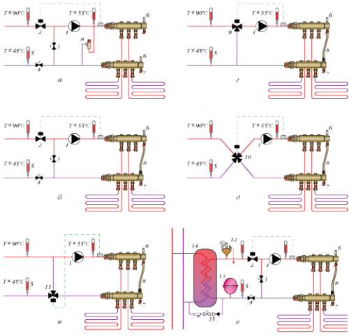
Below are the most common diagrams of mixing units, but in fact there are much more of them. Mixing of coolants can be done both before the collectors and directly at each outlet of the collector groups. In this case, each collector group will need to be equipped with its own thermostats, flow meters and valves.
Diagrams of mixing units (this is what an assembled heated floor unit looks like):
- Mixing unit for Valtec underfloor heating for one circuit (up to 20 m2.)
- Mixing unit for Valtec underfloor heating for one circuit (up to 20 m2) with automatic adjustment
- Valtec underfloor heating manifold for 2 - 4 circuits (20-60 m2.)
- Mixing unit for Valtec underfloor heating for 2 - 4 circuits (20-60 m2) with automatic adjustment
- Valtec underfloor heating manifold for 3-12 circuits (30-150 m2.)
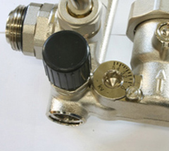
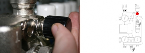
Using a balancing valve, the ratio of the flow rates of hot coolant and cold coolant from the return line is adjusted. The temperature in the heated floor circuit is actually set. The valve is turned using a hex wrench. To prevent the valve from accidentally moving, it is secured using a clamping screw. The valve also has a flow scale - the valve’s throughput from 0 to 5 m3/hour.
This valve is used to connect the mixing unit with all other elements of the system. The valve can also be turned using a hex key.
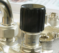
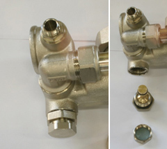
This is a safety valve whose task is to protect the pump from a mode in which the flow of coolant through it stops. This valve is activated if the pressure in the system drops to a set value. The value is set using a knob.
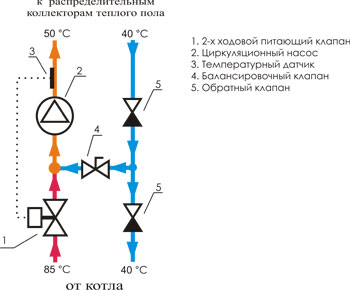
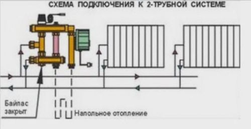
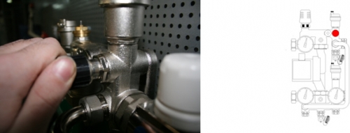
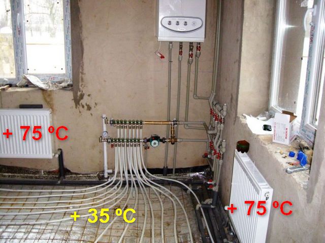
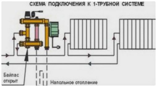
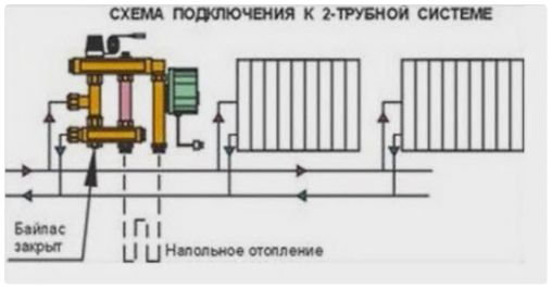
Also, the schemes differ depending on whether the heating system is single-pipe or two-pipe. For example, with a single-pipe system, the bypass is always in the open position so that part of the hot coolant can always flow further towards the radiators (photo below).

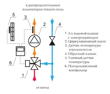
In a two-pipe heating system, the bypass is closed, since it is not necessary (photo below).
Please note that the underfloor heating manifold group does not have to be installed before radiator circuit. If the area of the house is not too large and the drop in coolant temperature is not too great, then a manifold with a mixing unit can be installed on the return of the radiator circuit.
Setting up a mixing pump unit for heated floors
After installing the mixing unit according to the selected scheme, its operation must be adjusted. The installation itself is quite simple, you only need to connect the pipes to each other, but the setup will require some explanation.
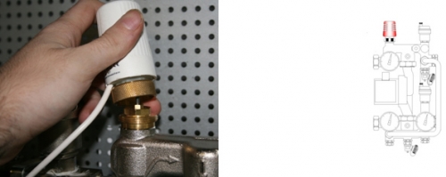
- The thermal head or servo must be removed so that it does not affect the assembly during the setup process.
- The bypass valve should be set to the maximum position - 0.6 bar. If the valve accidentally operates during the adjustment process, the result will be incorrect. Therefore, it should be installed in a position in which it will not work.
- Next, you should calculate the position of the balancing valve of the heated floor circuit. Further, for convenience, we will designate 1 as the radiator circuit, 2 as the heated floor circuit.
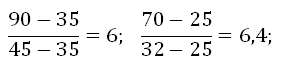
Calculated using the formula:

t1- temperature of the coolant in the supply pipe of the radiator circuit (high-temperature circuit);
t2feeds- temperature of the coolant in the supply pipe of the heated floor circuit;
t2rev- temperature of the coolant in the return pipe of the heated floor circuit;
Kυt- coefficient=0.9.
Calculation example:
Let us assume that t1=95 °C, t2feed = 45 °C, t2rev = 35 °C. Substitute the values into the formula:
The resulting value Kυb is set on the balancing valve.
- Next you need to configure the pump.
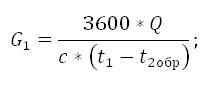
Calculated using the formula:
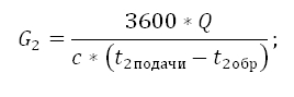
G2- coolant flow in the heated floor circuit - in the secondary circuit;
Q- the sum of the thermal powers of all devices connected after the mixing unit;
c- heat capacity of the coolant. If the coolant is water, then c=4.2 kJ/(kg*°C);
t2feeds And t2rev coolant temperature in the heated floor circuit: on the supply pipe and in the return pipe;
Calculation example:
To calculate the pressure loss in the underfloor heating circuit, it is necessary to perform a hydraulic calculation. For convenience, you can use free program for calculations on the website of the mixing unit manufacturer, for example, using the Valtec.prg program.
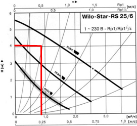
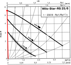
Using the graphs below, you need to determine the pump speed.

First, we mark the point that corresponds to the flow and pressure of the pump. The curve that is above the obtained point will correspond to the pump speed. The resulting flow rate = 0.86 m3/hour, pump pressure = 4.05 m w.c.
Pressure losses in the circuits after the mixing unit taken with a margin of 1 m in.st.
ΔPн = ΔPс + 1 = 4.05 + 1 m w.st.
Pump schedule:
If for some reason it is not possible to calculate the pump, you can skip this stage settings. In this case, it is necessary to set the pump to the minimum position. If later, during the process of balancing the system, it turns out that the speed is not enough, then simply set the pump to a higher speed.
- The next stage is to balance the heated floor branches.
First you need to close the balancing shut-off valve of the radiator (primary) circuit. We remove the cover from the valve and turn it clockwise all the way with a hex key.
The branches of the heated floor circuit are balanced using balancing valves. If after the mixing unit there is only one branch - one heated floor circuit, then there is no need to balance anything.
How does balancing work?:
- The balancing regulators must be opened to maximum;
- On the branch with the maximum flow deviation (actual flow from the design flow), the valve must be closed to the required size.
- All branches of the heated floor are adjusted in the same way.
- If the flow rate is lost after balancing the branches, it is necessary to correct it again.
- If it is not possible to establish the required flow rate even with the valves open, the pump must be switched to a higher speed.
- Next, you need to link the mixing unit for the heated floor with the rest of the heating devices.
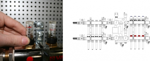
First of all, we open the balancing shut-off valve of the radiator circuit, which we closed at the very beginning. It is necessary to open it to the position that will provide the required coolant flow.

Coolant flow can be controlled using flow meters. It is also possible to control the return of the heated floor.
Calculated using the formula:
We already know all the values from previous calculations, so we calculate:
- Now we set up the bypass valve.
We set the valve pressure; its value should be 5 - 10% less than the maximum pump pressure at a given speed. The maximum pump pressure value must be determined from the pump characteristics.
The pump bypass valve should only open in a situation where the pump is working to build up pressure and there is practically no water flow.
The graph below shows how the bypass valve value is determined.
In the absence of water movement in the pipeline at first speed, the pump pressure is 3.05 m w.c. or 0.3 bar. On average speed- 4.5 m east. or 0.44 bar, at maximum - 5.5 m w.st. or 0.54 bar.
We set the value on the bypass valve to 0.54 - 5% = 0.51 bar.
It is necessary to check the uniform heating of the heated floor branches and the correct temperature ratio in the circuits.
The following equality must be satisfied:
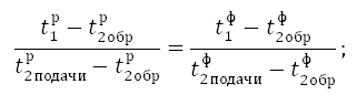
Index "R" means that the value is calculated, and the index "f"- factual.
If the equality is not satisfied, then close the balancing shut-off valve of the radiator circuit by ¼ turn and again take readings and perform calculations.
If the equality is satisfied, then the mixing unit is working correctly, it is necessary to install the thermal head or servo drive in place, put protective caps on all elements that require it, and tighten the balancing valve screw.
Calculation example:
The deviation in values is 6.6%, which is less than 10%. This means that the mixing unit is configured correctly, you can install the thermal head and protective caps and begin operating the heating circuit.
The heating mixing unit is installed in a manifold cabinet, which is usually located in and next to a room with heated floors. But you can also install it next to the heating boiler if the distance to the heated floor is not too great. You can assemble all the elements of the mixing unit yourself, or you can purchase a finished product. It all depends on your skills and knowledge.
Water heated floor is the most favorable and economical type of heating.
An integral part of a water underfloor heating system is the mixing unit.
According to sanitary regulations, the floor covering must have a temperature of no more than 31 degrees Celsius.
The unit lowers the temperature of the coolant which often has a high temperature for the floor and our feet.
Almost always the coolant needs to be supplied with heat:
heating radiators
water heaters (indirect heating boilers).
or some other device that requires more heat.
In our climatic conditions, a water-heated floor is sometimes not enough to heat a private house or any other room.
Therefore, it can ideally only work in conjunction with higher temperature heat consumers:
heating radiators - which require coolant from 65 to 75 degrees
water heaters (indirect heating boilers) - which need the same 65 - 75 degrees
(and raise it to 80 degrees once a day - to kill salmonella bacteria formed in hot drinking water)
Therefore, the heating boiler of a private house needs to heat and supply coolant to the heating system at a supply temperature of at least 65 degrees,
and sometimes even 90 degrees (which is extremely undesirable)
or any other devices that require high temperature heat.
But the comfortable temperature of a warm floor for a person’s feet is no more than 31 degrees
Therefore, the coolant going into the water-heated floor needs to be somehow lowered so that the flow is no more than 40 degrees.
It is by lowering the temperature
from 65-80 degrees to 20-40 and is engaged
pumping and mixing unit for water heated floors.
It can be mounted either in front of a heated floor manifold if there is only one, or in front of several underfloor heating manifolds.
The unit can also be used in combination with a central heating system, but only through a special heat exchanger.
Thus, we do not “invade” the uncontrolled central heating system, but only transfer heat to our circuit or circuits of the water heated floor, independent of the central heating.
For central heating, as a rule in apartments - only use through a heat exchanger can never harm your home.
For a private home or any independent heating system controlled by you or your installer, there is room to develop using heated floors in any necessary places.
Important. The boiler can heat the heating fluid of a private home up to 95 degrees (preferably no more than 80 degrees)
When installing a screed, these numbers increase, but should not exceed 51-55 degrees.
According to these requirements, the direct use of coolant is excluded, so there is a need to buy a mixing unit for a heated floor. Mixing unit for heated floors - lowers the temperature going into the water heated floor. Its main function is to lower the temperature of the coolant for the heating elements of the heated floor.
The temperature decreases due to the mixing of hot fluid flows from radiators with the so-called “return”, cold flows. As a result, coolant cooled to an acceptable value is supplied through the circuit.
Advantages of mixing units for water heated floors
First of all, you need to buy a mixing unit for a heated floor to protect the heating elements from overheating. But installing a unit in a heating system is not only a necessity, but also an opportunity to obtain a large number of advantages:
Advantages of using a pump-mixing unit for heated floors:
- Safety for human health and eliminating the risk of overheating of heating elements.
- Economy - using a thermal mixer reduces electricity costs by 25-35%.
- High hygiene - maintaining the system does not cause any inconvenience. Cleaning is done in a short time, and the surface dries quickly, which prevents the formation of fungal growths and mold.
- Durability - each element of the system is made of modern materials of increased strength. The minimum service life of the elements is up to fifty years.
How to choose the right mixing unit
The general principles of operation of the mixing unit look like this: a high-temperature coolant flow enters the distribution manifold, where a thermostat or temperature reading sensor is located.
As soon as a high temperature is detected, a valve opens, through which a flow of liquid of a lower temperature enters. Mixing and mixing of cold liquid with hot liquid occurs, or vice versa.
Once the optimal temperature is reached, the hot liquid supply automatically stops. The corresponding damper is closed.
The mixing unit for underfloor heating not only regulates heating, but also ensures the circulation of coolant in the system. Its work is carried out due to the following elements:
- Safety valve - supplies the volume of hot coolant. The amount of liquid depends on the temperature that should be obtained after mixing.
- A circulation pump is a device that circulates coolant along the system circuit, uniformly heating the entire functioning surface of the heated floor.
Additionally, the design may include a bypass to protect the system from overloads, drainage and shut-off valves, automatic air vents. The use of various elements depends on the tasks for which the mixer is needed.
Important. You can buy a mixing unit for heated floors at a low price in our store. The best Moscow specialists in installing heated floors will help you choose the necessary components and elements.
The mixing unit is installed before entering the heated floor circuit, but its location is not strictly regulated. This can be a place either near the underfloor heating system itself or in a separately equipped boiler room.
Differences between mixing unit systems for heated floors
The main difference between underfloor heating units is the design safety valves different types. The most commonly used are two types of valves: two-way and three-way.
The two-way valve has a thermostatic head with a liquid-type sensor. It determines the flow of hot liquid based on the data it captures. As a result, hot liquid from the boiler is supplied to the circulating cold coolant, and the heated floor is evenly heated. This type of mixing prevents the system from overheating and significantly increases its operating time. The low-flow valve ensures smooth heating, without pressure surges or overloads.
The use of such valves is most preferable when installing heated floors of a small area. If the area exceeds 200 m2, then the use of such a system is unjustified.
A three-way valve for a heating floor mixing unit is a combined option when the role of a supply valve and a balancing valve is combined. The principle of operation is the opposite, that is, the hot coolant is mixed with the cold “return” liquid.
This design must be equipped with servos connected to thermostatic devices that change the heating temperature to suit the conditions outside.
The flow of liquid inside such a valve is regulated using a damper, which is located between the pipe coming from the boiler and the “return”. The valve position is adjusted in any convenient way, depending on the required volume of heat.
Three-way valves are universal devices that are needed for a system with weather controllers, when laying heated floors over a large area, for installation in a system with a large number of heating elements.
Flaws:
- Possible temperature surges if the incoming flow of hot coolant is significantly greater than the cold liquid.
- The high throughput of the valve can greatly increase the heating temperature even with a minimal change in the position of the damper.
But these shortcomings cannot influence the decision to buy a mixing unit for a heated floor with a three-way valve. The use of weather-sensitive controllers can completely or partially solve these problems. When the temperature drops, the sensor is able to regulate and set the most comfortable temperature in the building. This is always true for a large area, when a drop in temperature outside the window by 3-5 degrees can lead to an uncomfortable temperature inside the room.
An additional advantage of automation is that readings are taken every 20-60 seconds, and if the values are below the calculated values, the damper is smoothly adjusted. If there are no people in the room, you can lower the heating temperature and thus save energy.
Various schemes of pumping and mixing units for heated floors
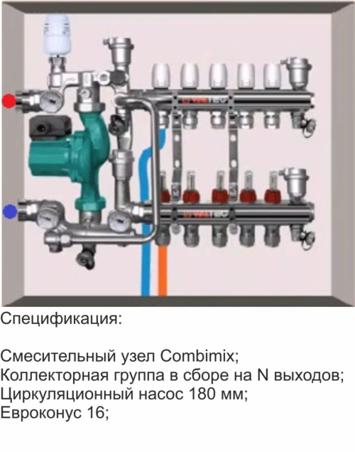
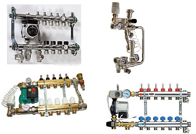
The design of the units may differ depending on the components used. As an example, you can consider the schemes from the Italian brand Valtec:
Components from this manufacturer meet the highest requirements and are recommended for use if you need to buy a pumping and mixing unit for installation in your home yourself.
First, for classification, you can consider several node schemes, starting with an elementary one, for a small area:
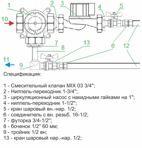
1. The area is no more than 20m2, with one circuit and manual temperature control. Connection complete set: 6-connector with metal-plastic pipe, 10-hot circuit, 11-return. This is the easiest way to connect. Additionally, an air vent is installed at the inlet and outlet - Ball Valves.
2.The heating area is up to 20m2, with one circuit, automatic adjustment using an external sensor with a thermal head. Connection: 1 - thermostatic valve is connected to the ball valve, (3), 5 - hot circuit, 6 - return, 18 - pump for the mixing valve, 11 and 22 - circuits of the underfloor heating system. As in the first option, you can install an automatic air vent.
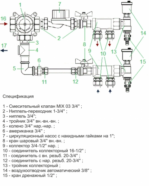
3. The area of the room is from 20 to 60 m2, the number of circuits is from two to 4, for automatic temperature control a servo drive, sensor and thermostat are required. Installation: 10 - connector for installation, 16 - hot circuit, 17 - cold circuit.
4. Area up to 60 m2, number of circuits from two to four, automatic adjustment from temperature sensors. Installation: 3 - installation of taps for hot and cold circuits, 7 - pump to mixing valve, 12 - connection points for underfloor heating pipes.
The price of a mixing unit for a heated floor is calculated based on many factors - the volume of the heated area, the quality and brand of components, and the number of additional elements. A detailed calculation can be made by receiving a free consultation from us.
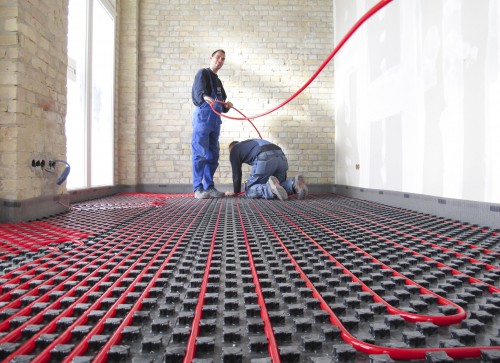
It is difficult to surprise anyone nowadays with a home heating system that operates on the principle of heating the floor surface. More and more owners of suburban housing, if they have not already switched, are seriously considering the prospects of switching to this effective and comfortable scheme for transferring heat from boiler equipment to the premises. One option is to organize water-heated floors. Despite the considerable complexity of their installation, they are very popular due to their economical operation, and due to their compatibility with an existing water heating system, of course, after certain modifications to the latter.
In general, it’s hardly worth starting to independently create water-based “warm floors” without having any experience in plumbing and general construction work. Every nuance is important here - from the choice of pipes and their layout, from the correct thermal insulation of the floor surface and pouring the screed - to the installation of the hydraulic part with subsequent precise debugging of the system. But this is how the typical Russian home owner works: he wants to try everything himself. And if their hands are full, then many try to carry out such work on their own. To help them, this publication will discuss one of the most important components of such a system. So, what is it for, how is it designed, and is it possible to make a mixing unit for a heated floor with your own hands at home?
What role does the mixing unit play in a “warm floor” system?
The traditional heating system, which involves the installation of heat exchange devices in rooms (radiators or convectors), is a high-temperature one. The vast majority of boilers of any type are designed for this purpose. The average temperature in the supply pipes in such systems is maintained at about 75 degrees, and is often even higher.
But such temperatures are absolutely unacceptable for “warm floor” circuits for a number of reasons.
- Firstly, it is completely uncomfortable to walk on a surface that is too hot and burns your feet. For optimal perception, temperatures in the range of 25÷30 degrees are usually sufficient.
- Secondly, not a single floor covering “likes” strong heating, and some of them simply quickly fail, lose their appearance, or begin to swell or develop cracks and cracks.
- Thirdly, high temperatures also negatively affect the screed.
- Fourthly, pipes of embedded circuits also have their own temperature limit, and given their rigid fixation in the concrete layer and the impossibility of thermal expansion, critical stresses are created in the pipe walls, leading to rapid failure.
- And fifthly, taking into account the area of the heated surface involved in heat transfer, high temperatures to create an optimal microclimate in the room are completely unnecessary.
How to achieve such “parity” of coolant temperatures in the system. There are, of course, modern heating boilers designed to work with “ warm floors", that is, capable of maintaining the temperature in the supply pipe at 35-40 degrees. But what then to do with the fact that the house has both radiators and underfloor heating - organize two systems? It’s not profitable at all, it’s complicated, cumbersome, and difficult to manage. In addition, such boilers are still quite expensive.
It makes more sense to make do with existing equipment, simply making the necessary changes to the circuit layout. The optimal solution is to mix hot coolant with cooled coolant that has already given off heat to the premises in order to reach the required temperature level.
By and large, this is no different from the process that we go through many times every day, opening water tap, and by rotating the “thumbs” or moving the lever, we achieve the optimal water temperature for taking water procedures, washing dishes and other needs.

It is clear that the mixing unit itself is much more complex than a regular faucet. Its design must ensure stable, balanced circulation of coolant in the heated floor circuits, correct selection of the required amount of liquid from the supply and return pipe, the necessary “circularity” of the flow (when there is no need for heat flow from the boiler), simple and clear visual control of the system parameters. Ideally, the mixing unit should itself, without human intervention, react to changes in the initial parameters and make the necessary adjustments to maintain a stable heating level.
This entire set of requirements, at first glance, seems very complex, difficult to understand, and even more so to implement independently. Therefore, many potential owners turn their attention to ready-made solutions– complete mixing units sold in stores. Appearance Such products, indeed, inspire respect for their “sophistication”, however, the price is quite often simply frightening.
But if you delve into the very principle of operation of the mixing unit, understand where, how and due to what the mixing process occurs, if you clearly imagine the direction of the coolant flows in it, then the picture becomes clearer. But in the end it turns out that assembling such a unit by purchasing the necessary parts and using your skills in installing plumbing products is a completely feasible task.
Let's make a reservation right away - in the future we will mainly talk about the mixing unit. It is subsequently connected to the “warm floor” collector, about which, of course, certain mentions are simply inevitable. But the collector itself, that is, its structure, principle of operation, installation, balancing - this is a topic for a separate publication, which will certainly appear on the pages of our portal.
Basic diagrams of mixing units for “warm floors”
There are a considerable number of schemes of mixing units for water-heated floors, differing in complexity, layout, saturation of control and automatic control devices, dimensions and other characteristics. It is difficult to consider all of them, and there is no need to do so. Let us pay attention to those that are simple and understandable, do not require complex elements, and the assembly of which can be carried out by anyone with some knowledge of plumbing installation.
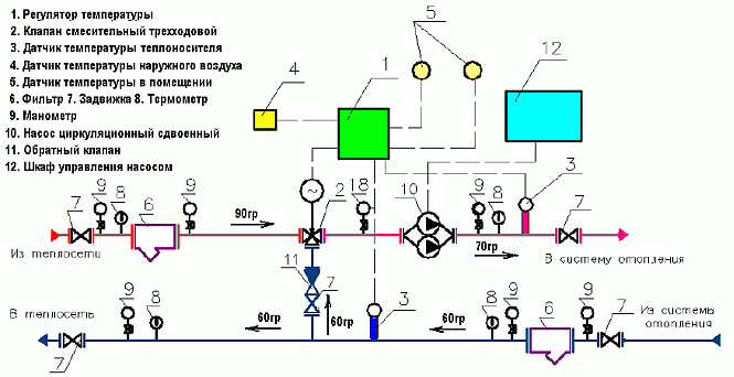
In all the diagrams below, the pipes of the common heating circuit are located on the left. The red arrow shows the entrance from the supply line, the blue arrow shows the exit to the return pipe.
On the right side are the connections of the pumping and mixing unit with the “combs”, that is, with the underfloor heating manifold, also indicated by red and blue arrows. It should be understood that the “combs” of the collector can be attached directly to the unit or placed at a certain distance and connected by piping - it all depends on the specific conditions of the system. Often circumstances develop in such a way that the mixing unit is located in the area of the boiler room, and the collector is already moved into the room, to the place from which it is most convenient to lay out the “warm floor” circuits. This does not change the essence of the operation of the pumping and mixing unit.
Translucent arrows in red and blue shades show the directions of movement of coolant flows.
Scheme 1 – with a two-way thermal valve and a series connection of a circulation pump
One of the simplest mixing unit designs to implement. To begin with, look at the drawing.
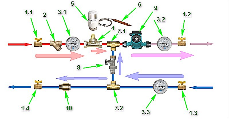
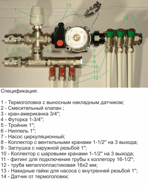
Let's look at the components:
- Pos. 1 – these are shut-off ball valves. Their task is only to completely shut off the pumping and mixing unit if necessary, for example, when there is no need for floor heating, or when certain maintenance and repair work is required.

There are no special requirements for the cranes other than high quality products. They perform exclusively the role of shut-off valves, and do not take any part in regulating the operation of the heating system. In principle, only two positions should be used on them - fully open or fully closed.
Cranes pos. 1.1 and 1.4, which cut off the entire underfloor heating system from the general heating circuit, are mandatory. Cranes pos. 1.2 and 1.3 - can be placed between the mixing unit and the manifold at the discretion of the master, but they will never interfere. It becomes possible to cut off the collector unit for carrying out any work without covering the actual contours of the heated floor, that is, without disrupting the adjusted settings of each of them.
- Pos. 2 – filter rough cleaning(the so-called “oblique” filter). It probably cannot be called an absolutely essential element of the mixing unit, but it is inexpensive and can affect the longevity of the system.
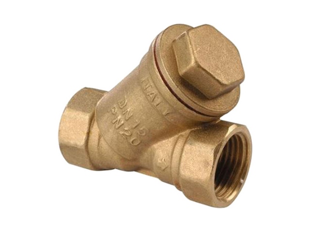
It is clear that such filtering devices are required to be installed in a common boiler room. However, when the coolant circulates in a branched system, it cannot be ruled out that solid inclusions will enter it and be transferred, for example, from heating radiators. And the pumping and mixing units and the following manifold units are saturated with control elements for which solid impurities are extremely undesirable, since they can destabilize the operation of valve devices. This means that it would be wiser to supplement your mixing circuit also with an individual filter.
- Pos. 3 – thermometers. These devices help to visually monitor the operation of the mixing unit, which is especially important when debugging and balancing the “warm floor” system. All subsequent diagrams will show three thermometers - on the supply pipe from the common circuit (pos. 3.1), at the inlet to the manifold, that is, showing the temperature of the flow after mixing (pos. 3.2), and on the “return” after the manifold, before the branch from it to the mixing unit (pos. 3.3). This is probably the optimal location, clearly showing both the quality of mixing and the degree of heat transfer of the “warm floor”. Ideally, the difference in readings on the supply and return manifold combs should not be higher than 5÷10 degrees. However, some craftsmen make do with fewer thermometers.

The design of thermometers may vary. Some people prefer overhead models that do not require insertion into the system (in the illustration on the left). But devices with a probe sensor, which is screwed into the corresponding socket of the tee, still have greater accuracy of readings, and simply reliability.
- Pos. 4 – two-way thermal valve. This is exactly the same element as is installed on heating radiators. In this scheme, it is he who will quantitatively regulate the flow of hot coolant entering the “warm floor” system.
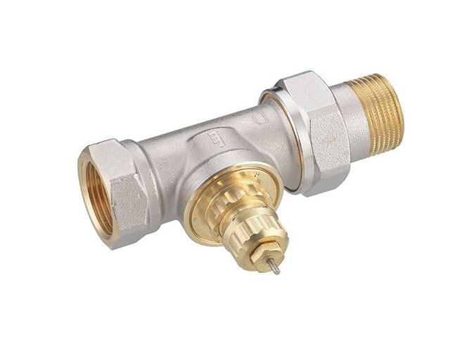
There is one nuance here - such thermal valves differ in purpose - for one-pipe or two-pipe heating systems. But this difference is important when installing them on a separate radiator. But for a mixing unit that serves several “warm floor” circuits, increased productivity is important. This means that you should select a valve for single pipe systems, even if the entire system is organized on a two-pipe principle. These valves are even visually larger in size; they are usually marked with the letter “G” and are distinguished by a gray protective cap.
- Pos. 5 – thermal head with a remote patch-on sensor (item 6). This device is put on (screwed on or secured with a special adapter) onto the thermal valve and directly controls its operation. Depending on the temperature readings on the remote sensor, which is connected to the head by a capillary tube, the valve will change position, slightly opening or completely blocking the passage for the hot coolant.
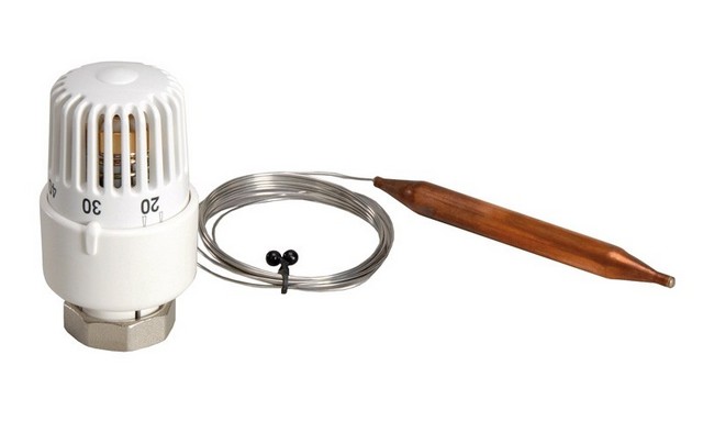
Immediately the question is - where to install the temperature sensor? There are two options - it can be applied to the supply pipe to the manifold, after the mixing unit, behind the pump, or on the return pipe of the manifold, before it branches into mixing. There are adherents of both methods.
— In the first case, a constant temperature of the coolant supply to the heated floor circuits is ensured. Stable operation is ensured and the likelihood of floor overheating is reduced to almost zero. But, at the same time, the system, if it is not additionally equipped with thermostatic elements directly on the circuits, ceases to respond to changes in external conditions. That is, a change in the temperature in the room will not in any way affect the heating level of the coolant supplied to the “warm floor”.
— In the second case, with a temperature sensor on the return, temperature stability is ensured in this particular area. That is, the heating level of the coolant entering the collector after the mixing unit may fluctuate. This scheme is good in that the system responds, for example, to cold weather, automatically raising the supply temperature and lowering it when it warms up. Convenient, but there are certain risks. So, during the initial heating of the floor screed, too hot coolant may initially flow into the circuits. A similar situation is quite likely with a sudden influx of cold, for example, with windows wide open in case of emergency ventilation of the room.
Changing the position of an overhead temperature sensor is not so difficult if you provide places for its installation in advance. So you can try both options and then choose the optimal one.
We will not talk about the design of the thermal valve and thermostatic head - there is a separate publication on this topic.
How does the thermostatic control system for heating radiators work?
Installing additional devices allows you to ensure constant comfortable conditions in the room, regardless of changes in external conditions. Purpose, device, installation and operation are in a special article on our portal.
- Pos. 7 - ordinary plumbing tees, between which a kind of bypass is laid - a jumper, through which the coolant will be taken from the “return” for mixing with the hot flow. In fact, the 7.1 tee becomes the main mixing zone.
- Pos. 8 – balancing valve. It is used to fine-tune the system in order to achieve optimal readings of the circulation pump in terms of pressure and performance. It may be necessary to reduce (or, as plumbers often say, “strangle”) the flow through the return jumper so that unnecessary areas of excessive vacuum or high blood pressure, and the pump itself would work in optimal mode.
There are no tricks in this device - in fact, it is an ordinary valve that limited the flow. You can also install an ordinary plumbing valve here. The block crane shown in the illustration is more advantageous from the point of view that it is compact, and also because no one can accidentally knock down the settings made with a hex key, for example, children who simply want to turn the flywheel out of curiosity. So it’s better, after setting up the system, to close the adjustment unit with a lid - and be relatively calm.
- Pos. 9 – circulation pump. The pump that services the entire heating system as a whole will not be able to provide circulation through long “warm floor” circuits, especially if several of them are connected to the collector. So each mixing unit is equipped with its own device.

Setting up a heated floor system will be easier if the circulation pump has several switchable operating modes.
How to choose the right circulation pump?
The variety of models nowadays is extremely large, which can even confuse an inexperienced consumer. More details about the device and the rules for their selection and installation can be found in a special publication on our portal.
- Pos. 10 – check valve. A very simple and inexpensive plumbing fixture that prevents unauthorized flow of coolant in the opposite direction
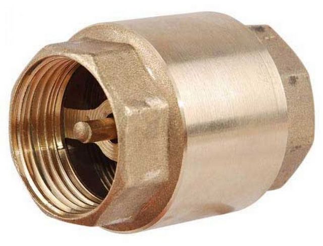
It could seem. That there is no special need to install it. However, such insurance may not be superfluous. For example, a situation where the thermal valve, due to sufficient temperature on the manifold, is completely closed. The circulation pump works and, in principle, is capable of sucking coolant from the common “return” pipe of the system. And there the temperatures are completely different, much higher than even at the “warm floor” supply. That is, such a reverse current can greatly disorient the operation of the mixing unit.
With the elements and their mutual arrangement - everything. Let's see how such a node works.
The coolant flow from the common supply pipe bypasses the “oblique” filter and thermometer and reaches the thermostatic valve. Here it decreases due to a decrease in the lumen of the channel for the free passage of liquid. The thermal head closely monitors the dynamics of temperature changes, slightly opening or closing the valve device.
The circulation pump operating in the “warm floor” circuit leaves behind a vacuum zone, which “draws in” the regulated flow of hot coolant. But since the pump performance does not change, the “shortage” is compensated by the flow of cooled coolant from the return line coming from the collector through the bypass jumper.
At the point of connection of the flows (in the upper tee), their mixing begins, and the pump pumps the coolant that has already been brought to the required temperature. If the temperature at the thermal head sensor is sufficient or excessive, then the thermal valve will be closed altogether, and the pump will begin to drive water only along the “warm floor” circuits, without external replenishment, until it cools down. As soon as the temperature drops below the set value, the thermal valve will slightly open the passage of the hot coolant to reach the required value after the mixing point.
With stable operation of the system, brought to its design capacity, the flow of hot coolant from the general supply is usually not so large. The valve is mostly in a slightly open state, but at the same time it reacts very sensitively to changes in external conditions, ensuring temperature stability in the “warm floor” circuits.
A similar principle, in which the entire volume of coolant pumped by the circulation pump is sent to the “warm floor” collector, is called a mixing unit with a series connection of the pump.
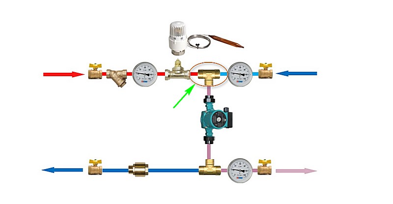
Scheme 2 - with a three-way thermal valve and a series connection of a circulation pump
This scheme is very similar to the previous one, however, it also has its differences.

The main difference is the use of not a two-way, but a three-way thermal valve (item 11) with the same thermostatic head. It took the place of the tee at the intersection of the supply line and the bypass jumper pipe.
In this case, mixing takes place directly in the thermal valve body. It is designed in such a way that when one coolant supply channel is closed, the second one is simultaneously opened slightly, which ensures greater stability of the mixing unit - the total flow rate is always maintained at the same level. This makes it possible to do without a balancing valve on the bypass.
Important - three-way thermal valves come in mixing and separation principle actions. In this case, what is needed is a mixing one, with perpendicular flow directions. Usually the corresponding arrows are placed on the body of the device, and it is difficult to make a mistake with this.

A three-way valve can be made without a thermal head - with its own built-in temperature sensor and a scale for setting the required outlet temperature. Some craftsmen prefer just this, thermostatic variety, as it is easier to install. True, a device with a remote sensor still works more accurately. In addition, when operating a system with a thermostatic three-way valve, there is a higher probability of unauthorized passage of high-temperature coolant to the collector.
Three-way separating valves, by the way, can also be used in a similar scheme. Only their installation location is on the opposite side of the bypass, and they already regulate the separation and redirection of the flow of cooled coolant to the mixing point, towards the pump.

A mixing unit with a three-way valve, due to its high stable performance, is more suitable for large collector junctions with several circuits of varying lengths. They are also used in the case of using weather-dependent automation, which often also involves automated control of the operation of the circulation pump. For small systems it does not justify itself, as it is more difficult to adjust.
The diagram below the question mark shows a check valve (pos. 10.1). In principle, it is justified if for one reason or another the circulation pump of the unit does not work, for example, the automation gave a command to stop circulation. In such situations, the jumper from the return to the three-way valve can turn into a completely uncontrolled bypass, which will upset the balancing of the system and affect the operation of other heating devices in the house. A check valve can prevent this phenomenon. However, many experienced craftsmen question the likelihood of such situations occurring, and consider the valve in this area to be completely unnecessary and even harmful, as providing unnecessary hydraulic resistance.
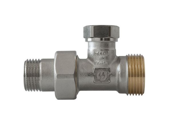
Scheme 3 - with a three-way thermostatic valve operating with converging flows and a series connection of a circulation pump
On sale you can find thermostatic valves that are organized on the principle of mixing two flows converging along one axis. With them, the assembly diagram of the pumping and mixing unit can take the following form:
It is not difficult to distinguish such thermostatic taps by their characteristic shape and printed diagrams (pictograms) of the direction of flow.
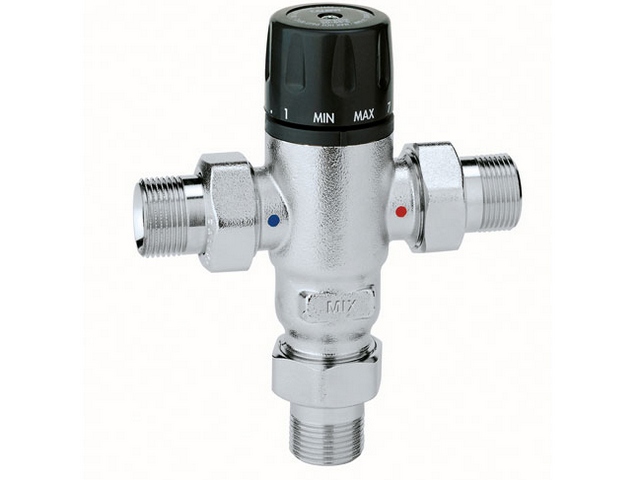
The circuit shown above is good for its compactness. There is no bypass at all, as its role is completely performed by the mixing valve itself. Otherwise, this is the same circuit with the principle of connecting a circulation pump in series.
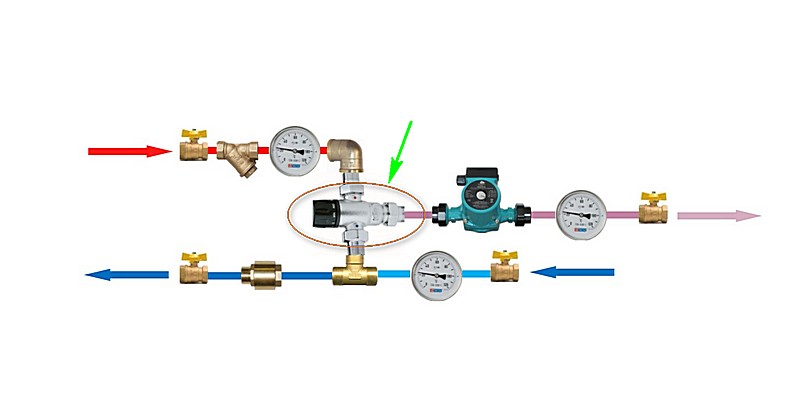
Scheme 4 - with a two-way thermal valve and parallel connection of a circulation pump
But this scheme is already significantly different from all those shown above:
This principle of unit structure involves the so-called parallel connection of the pump, literally on the bypass. But two meeting flows approach the upper point of this bypass - from the supply common system and from the collector return. A two-way thermal valve with a thermal head and a remote sensor is installed on the supply - everything is the same as in the first scheme. The pump providing circulation through the jumper takes both converging flows, and their mixing occurs in the tee at the top (highlighted by an oval and an arrow) and in the pump itself. But further, at the lower point of the jumper on the tee, the flow is divided. Part of the coolant with the temperature already leveled to the required level is sent to the “warm floor” supply manifold, and excess quantity– is discharged into the general “return” of the heating system.
This scheme attracts, first of all, its compactness. In conditions of limited space for installing a mixing unit, this is one of the acceptable solutions. However, it has many shortcomings. First of all, it is obvious that its performance is clearly inferior to units with a series pump connection. It turns out that a certain volume of coolant, after mixing and bringing it to the required temperature, is pumped by the pump in vain - it does not participate in the operation of the heated floor circuits and simply goes into the “return”.
In addition, such a system is quite difficult to balance, and often requires the installation of additional balancing and (or) bypass valves.
It is interesting that many ready-made factory-assembled mixing units are organized in a parallel circuit - most likely for reasons of maximum compactness. And craftsmen are coming up with ways to convert them into a more “obedient” circuit - with a series pump.
Scheme 5 - with a three-way thermal valve and parallel connection of a circulation pump
Finally, another diagram:
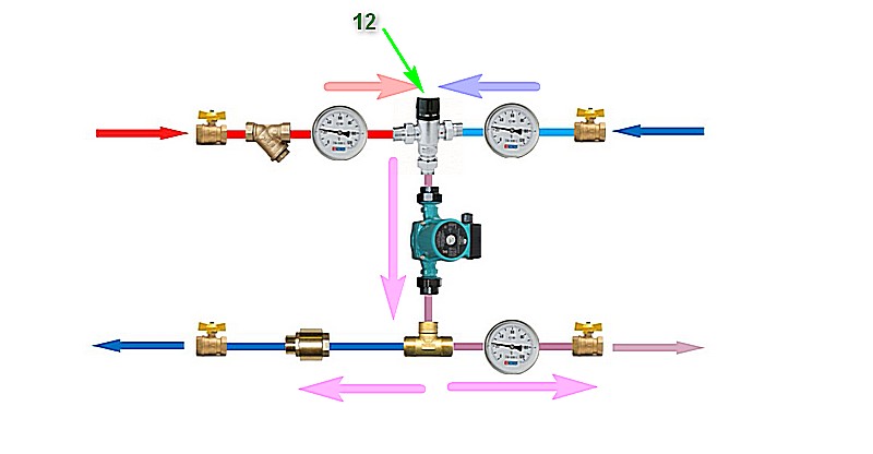
It probably doesn’t need additional comments, since it practically repeats the previous one. The difference is the use of a three-way thermal valve or thermostatic mixer (item 12) at the highest point above the pump. The direction of converging flows before mixing and their separation on the trench after the pump is clearly demonstrated by arrows.
Of course, there are much more complex circuits, which are practiced by manufacturers of ready-made pumping and mixing units. But for self-production, it is better to choose something that is easy to assemble and reliable in operation, choosing one of the proposed schemes and implementing it in a way convenient for yourself and for specific installation conditions.
Performance of the mixing unit and the required pressure of the circulation pump
When selecting components for self-assembly of a pumping and mixing unit, it is necessary, in addition to the connecting diameters of pipes and required elements, to also know some operational parameters. In particular, the pump itself and any thermal valve or mixing valve must meet performance requirements. Simply put, this is the ability to pass through oneself the required amount of coolant per unit of time. And for the pump, the pressure created is also important, since it must ensure stable circulation of the coolant in all “warm floor” circuits connected to the mixing unit.
Typically, for systems with complex structures, such calculations are carried out by specialists in the field of hydraulics and heat engineering. However, simple calculations for a “warm floor” system created by yourself, with a completely acceptable level of accuracy, can be carried out independently.
Mixing unit performance.
In matters of performance, the circulation pump is the “active link”. That is, it is he who must ensure the pumping of the required volume of coolant through the circuits, which will release part of the accumulated energy to heat the room. The thermostatic element of the mixing unit must be able to pass such a volume through itself. Valves can be produced with different capacities, and some of them, in addition, have the ability to be preset to a certain capacity per unit of time.
It is clear that the larger the area of the heated premises, and the higher the requirements for the “warm floor” system (whether it will be the main source of heat or it is planned only to increase the overall comfort in the premises), the more thermal energy must be supplied for heat exchange. And since the temperature difference between the supply and return collectors is usually kept constant, it is easy to calculate the volume of water required to transfer the required amount of heat.
We will not bore the reader complex formulas, or better yet, we’ll suggest using the built-in calculators, which will make the calculation as simple as possible.
The initial data will be the area of the premises in which the “warm floor” system is created. Moreover, there is a certain differentiation, depending on whether such heating will be the main one, or will be considered only as a means of increasing comfort in residential premises. For a bathroom, toilet, hallway or kitchen, it is better to consider the floor power from the point of view of the main heating.
Calculator for calculating the performance of a "warm floor" mixing unit
Pressure created by the pump of the mixing unit
The circulation pump of the mixing unit “has no one to rely on” - it must ensure the operation of all heating circuits, without the possibility of them being blocked due to insufficient pressure in the system. This is especially true in cases where the thermostatic element completely shuts off the supply of hot coolant and the flow from outside is suspended - circulation should not suffer.
Here indicators will come to the fore hydraulic resistance pipes, which are also subject to considerable pressure losses on the shut-off and control valves of the unit, with which it is usually quite saturated.
How many and what kind of pipes will you need?
This issue will not be discussed in this publication. The calculator located in the article on our portal dedicated to will help you calculate the required number of pipes.
It is clear that the pump will create an equal pressure value on the supply manifold for all circuits. During system adjustment, this parameter will be adjusted for each circuit separately using special balancing devices. This means that the calculation must be carried out for the longest circuit, in which the hydraulic resistance indicators will be maximum.
Below is a calculator that will allow you to quickly determine the minimum required pressure value. The necessary amendments have already been made to the calculation program hydraulic losses pressure in the shut-off and mixing elements of the unit.
Artificial floor heating is not the main method of heating premises. But to create truly comfortable conditions, especially in families with small children, installing such a system is more than advisable. Despite the apparent complexity of the design, all the work on installing a mixing unit for a heated floor can be done with your own hands, if you know some of the features of the circuit design. This article will help you figure this out.
Purpose of the mixing unit
On a note!
The control system is installed when the heating system is connected to a common heating system. If a separate heat generator is installed to ensure its operation, then there is no need for such a unit, since an individual source of thermal energy can be adjusted to any required temperature. However, this option is more suitable for a private house, where a mixing unit may be needed, especially on the first floors, where the radiators heat up more.The coolant entering the heating system from the boiler outlet, as a rule, has a temperature of about +95 ºС. As water moves through the pipes, its value gradually decreases, but, nevertheless, it reaches the radiators at a level of about 60 - 65 ºС. Therefore, all heating batteries belong to the class of high-temperature devices. It’s easy to verify this by even just lightly touching the radiator in a well-heated building.
The system is a little different. This is a low-temperature engineering design, since excessive heating of its pipes will lead not only to deformation of the finish coating, but also to the inconvenience of moving around the room, or even obvious discomfort. It is unlikely that anyone will enjoy walking on a hot floor (standing or sitting on it). Consequently, water must flow into the pipes that are laid underneath it at a different, lower temperature. According to standards, the surface should heat up to a level of +(30 – 35) ºС, no more. And even then, not everyone likes this.
Depending on the pipe laying scheme, the thickness of the screed, and the type of finishing coating, the water temperature at the entrance to the system is selected within the range of 40 - 55 ºС. This means that the coolant coming from the boiler must first be cooled. The mixing unit is designed to solve this problem.
Structural elements of the node
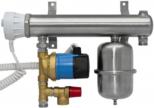
Pump
Responsible for the forced movement of coolant in underfloor heating pipes and mixing hot and cold water at the moment of operation of the shut-off valves. The approximate cost is about 2,390 rubles.
Collector block
The price of the finished product is from 15,850 rubles. It is a ready-to-install kit on which all the necessary devices are mounted.
It can also be made from a piece of pipe, which is “suppressed” at one end. To circulate the coolant, several bends are welded onto the pipe (one pair per system) according to the comb principle. But it’s easier to buy a collector block, since it’s quite difficult to arrange outlets and install shut-off valve elements yourself.

Its price is relatively low. For example, a collector for 2 separate heating circuits (6 in the figure) costs about 4,980 rubles.
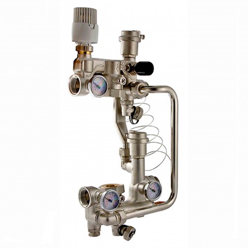
Valve with thermostat (2 or 3 way valve)
Its task is to ensure the supply of hot water when cooling the coolant in the floor heating system to set temperature(for her “mixing”).
Balancing valve
It is designed to bleed excess coolant into the return line when the rated pressure in the heated floor pipe is exceeded.
Additionally, a filter, temperature indicating devices, and so on can be installed. One of the possible scheme options is shown in the figure:
Although he is not the only one. Here are more connection examples.

Operating principle of the mixing unit
The diagram below explains everything clearly. But this is only one of the options, since mixing is carried out in different ways. The choice of a specific scheme depends on the area of the room in which the heating system is installed.

For a private house, a circuit with a two-way valve is used, since it fully provides effective work contours on areas up to 180 – 200 m².
Hot water from the boiler outlet flows both to the heating radiators and to the manifold of the mixing unit and is constantly “on duty” there as long as the valve damper is closed. As soon as the water in the circuit cools below the set limit, shut-off valves is triggered, and part of the coolant from the heating system enters the floor heating pipe, and excess liquid is removed into the return line.
Thus, uniform heating of the circuit is constantly ensured during operation.
Installation location
It is mounted where it is more convenient:
- The room has a heated floor.
- In a home boiler room.
- In a separate or common cabinet for collectors, if heating is organized in several rooms.
Installation features
- Plastic, relatively soft pipes () are used for the underfloor heating circuit. This is mainly due to their maximum bending radius, which is significantly smaller than that of metal products. But the SU manifold must be rigidly attached at the installation site.
- The mixing valve is always placed at the inlet of the circuit.
- All electrical devices (for example, a pump) are connected to the ground loop.
- The specifics of installation are determined by the layout of the heating system in the home. Possible options The connections of the mixing unit are shown in the figures.
- The final stage is setting up the automation elements according to the required system characteristics (valve response temperature, maximum pressure in the pipe, and so on). It is done individually for each circuit, and this issue requires separate, detailed consideration.
In principle, the information provided is quite enough to independently install a mixing unit in a private house or apartment. When installing heating circuits on large areas- its own nuances. For example, not 2 are used, but three-way valve+ additional automation elements. But this (like setting up the automation) is a separate topic, and it does not directly relate to the domestic use of mixing devices.